Note: Descriptions are shown in the official language in which they were submitted.
ROOFING SHINGLE SYSTEM AND SHINGLES FOR USE THEREIN
[00011
FIELD OF THE INVENTION
100021 This
invention relates to an improved roofing system and roofing shingles that
may be utilized in the roofing system. In particular, the invention relates to
roofing shingles
featuring unique dimensions and a roofing system that utilizes the shingles.
-1-
CA 2891785 2017-10-03
CA 02891785 2015-05-20
Attorney Docket No. 03398.000064.1
PATENT APPLICATION
BACKGROUND OF THE INVENTION
[0003]
Roofing products are often divided into three broad groups: shingles, roll
roofing,
and underlayment. Shingles and roll roofing typically function as outer roof
coverings designed
to withstand exposure to weather and the elements. Shingles and roll roofing
generally contain
the same basic components which provide protection and long term wear
associated with asphalt
roofing products. These components include a base material made from an
organic felt or
fiberglass mat which serves as a matrix to support the other components and
gives the product
the required strength to withstand manufacturing, handling, installation and
service in the
intended environment. An asphalt coating formulated for the particular service
application is
often applied to the base material to provide the desired long-term ability to
resist weathering
and to provide stability under temperature extremes. An outer layer of mineral
granules is also
commonly applied to the asphalt coating to form a surface exposed to the
weather which shields
the asphalt coating from the sun's rays, adds color to the final product and
provides fire
resistance.
[0004]
Typically, shingles are installed on a roof deck such that the shingles are in
a row
from left to right and the lateral edges of the shingles in the row are
contiguous with each other
so as to abut each other, i.e. their lateral edges are adjacent to one
another. Each row represents
a course and the shingles are applied in overlapping courses on the roof deck,
wherein the buttlap
portion of a subsequent course is placed on the headlap portion of a previous
course. The
headlap portion of a conventional shingle is at least as wide as the buttlap
portion of the shingle
S0 that when the shingles are installed on a roof deck in overlapping courses,
the entire buttlap
portion of a subsequent course has headlap beneath it. This manner of
installation prevents
leakage to the roof deck where the lateral edges of the shingles abut each
other.
-2-
CA 02891785 2015-05-20
Attorney Docket No. 03398.000064.1 PATENT
APPLICATION
[0005] In a typical roofing system, contiguous shingles in a row abut each
other at their
lateral edges. Thus, when the shingles are exposed to wet weather, it is
possible that leakage can
occur at the region where the shingles abut. To prevent that, overlapping
subsequent rows of
shingles are installed in an offset pattern and each shingle's headlap portion
is at least as wide as
the buttlap portion. Thus, when the shingles are applied to the roof in a
plurality of courses and
the buttlap portion of a second course of shingles is laid over the headlap
portion of a first row of
shingles there is always headlap present underneath the regions where the
contiguous shingles in
a row abut. Any water penetrating the places where lateral edges of shingles
abut contacts the
underlying headlap rather than the roof deck.
100061 Asphalt shingles are among the most commonly used roofing materials.
Asphalt
shingles, such as those disclosed in U.S. Pat. No. 6,990,779, have been used
extensively in
residential housing as roof covering due to their aesthetics, ease of
installation, water shedding
function, and excellent field performance over a long period of time. U.S.
Pat. No. 6,990,779
discloses a laminated roofing shingle system including a reduced-width headlap
portion and an
interply material that is installed under the buttlap portion in order to
compensate for the
reduced-width headlap portion and provide protection to the roof deck.
[0007] In some cases, prior art shingles may rely on redundant overlapping
to ensure
adequate water shedding performance, particularly in high wind or wind-driven
rain conditions.
For example, a typical prior art shingle know as a "3-tab shingle" would
require approximately
240 ft2 of sheet material to cover a 100 ft2 of roof area (also known as a
"square"). Other types
of shingles also require significantly high amounts of overlapping materials
to achieve adequate
performance for resistance to water infiltration.
-3-
CA 02891785 2015-05-20
Attorney Docket No. 03398.000064.1
PATENT APPLICATION
[0008] Various shingles have been developed that employ a shiplap or side-
lap feature
such that when applied to a roof deck at least part of the lateral edges of
neighboring shingles
overlap. U.S. Pat. No. 2,106,396 discloses single layer asphalt coated
shingles having serrated
edges having edge and corner elements. When the shingles are applied to a roof
deck, their
lateral edges overlap. The edge and corner elements of the shingles may be
utilized as guides for
laying the elements of each shingle in proper relation to each other in each
course and also for
properly relating the elements in one course to those in a subjacent course.
100091 U.S. Pat. No. 2,272,032 describes single layer asphalt roofing
shingles with
varying cross-sectional thickness to be arranged in offset overlapping
courses, wherein the side
edge portions of adjacent shingles in the same course overlap. The shingle has
longitudinal
zigzag edge contours, which shadow each other on either side of the shingle
such that the width
of the shingle is constant across the length of the shingle. When the courses
are installed, the
thicker portions of a subsequent shingle "nest" in the thinner portions of the
previously installed
shingle to provide the protection qualities of more heavily coated roofing
material.
[00010] U.S. Pat. No. 2,687,701 discloses single layer tabbed asbestos
cement roofing
shingles comprising projections on the front and rear edges. When the shingles
are applied to a
roof deck, their lateral edges overlap. The shingles comprise projections
which extend above
and over the buttlap portion of a previous course when a subsequent course is
installed. The
overlapping and projections are intended to create a more dimensional
appearance.
[00011] U.S. Pat. No. 3,919,823 discloses single layer asphalt roofing
shingles. The
shingles comprise various projections on the front edge. The shingles are
installed such that their
lateral edges overlap to create what is described as a "shadow effect" which
will vary depending
on the time of day.
-4-
CA 02891785 2015-05-20
Attorney Docket No. 03398.000064.1 PATENT
APPLICATION
[00012] U.S. Pat. No. 4,274,243 discloses a laminated asphalt roofing
shingle to be
arranged in overlapping courses to optically simulate tiles. The shingle has a
buttlap portion
with curved tile-like features and the left-most tile-like feature includes an
overlap portion that
extends over the adjoining edge of a neighboring shingle to hide the adjoining
edge between the
shingles.
[00013] U.S. Pat. Nos. 4,333,279 and 4,527,374 disclose strip or tabbed
single layer
asphalt shingles. The shingles comprise various edges at least one of which is
an alignment
edge. The shingles are overlapped using the alignment edge in order to achieve
a desired pattern
when the shingles are installed on a roof deck.
[00014] U.S. Pat. Appl. Publ. No. 2004/0182032 discloses a multi-layer
laminate shingle
with a reduced-width headlap portion. The shingle has a base layer and at
least a second layer
above the base layer. At one end of the shingle the base layer projects beyond
the second layer
while at the other end the second layer projects beyond the base layer. When
the shingles are laid
in a course along the roof, the projecting end of the second layer overlaps
the projecting end of
the base layer of the previously installed shingle, forming a shiplap joint
over all or substantially
all of the width of the shingle.
[00015] U.S. Pat. Appl. Publ. No. 2011/0185668 discloses a laminated
roofing shingle
system including a reduced-width headlap portion, wherein the roofing system
comprises a
plurality of courses, and wherein a trailing edge of a subsequently installed
shingle in a course
overlaps the leading edge of an adjacent previously installed shingle in the
same course.
1000161 In addition to certain of the shingles discussed above, various
shingles have
employed non-straight edge contours. U.S. Pat. No. 1,732,403 discloses a
tabbed strip shingle
and method of forming the shingle. The shingles are cut from a sheet of
roofing material,
-5-
CA 02891785 2015-05-20
Attorney Docket No. 03398.000064.1
PATENT APPLICATION
wherein the front edge profiles of the shingles are cut with a zigzag pattern
to form
complementary shingles. The tabs of the shingles are separated by parallel
slots and have a
generally triangular front edge with a small horizontal tip portion. When
installed, the small
horizontal tip portion of the tabs of shingles in a subsequently installed
course align with the
ends of the slots of shingles in a previously installed course. The shingles
require approximately
225 ft2 of sheet material to cover a 100 ft2 of roof area.
[00017] U.S. Pat. No. 1,846,635 discloses a method of cutting so-called
hexagonal strip
shingles without waste from a parent sheet of prepared roofing. Each shingle
has an exposed
edge that defines projecting tongues having three sides of a hexagonal shape
separated by
recesses. When installed the projecting tongues match with the recesses of
previously installed
shingles, i.e., the projecting tongues have an end breadth equal to the
breadth of the recesses in
the buttlap. The shingles may also have a headlap with projections and
recesses, wherein the end
breadths of the headlap projections are equal to the headlap recesses and
different from the
tongue end breadths and buttlap recesses. U.S. Pat. No. 1,846,635 further
discloses a formula for
calculating the average exposed width of the shingle and that the shingle has
a maximum width
("extreme width") that is twice the average exposed width plus the desired
overlap from a
successively installed shingle.
[00018] U.S. Pat. Appl. Publ. No. 2003/0172611 discloses shingles having a
headlap
region and a visual feature region, wherein the visual feature region includes
teeth and cutout
spaces that are identical in shape and size, with respect to each other. When
installed, an
alternating pattern is achieved along a vertical line extending up the
shingled roof between teeth
and cutout spaces of the visual feature regions of overlapped, vertically
adjacent shingles.
-6-
L000191 U.S. Pat. Appl. Publ. No. 2013/0160389 discloses shingles having a
headlap
portion with a non-straight longitudinal edge and a buttlap portion with a non-
straight
longitudinal edge, wherein the non-straight longitudinal edges do not shadow
each other laterally
across the shingle. U.S. Pat. Appl. Publ. No. 2013/0160389 further discloses a
roofing system
wherein at least a portion of the headlap portion of a shingle in a
subsequently installed course
overlaps at least a portion of the headlap portion of a shingle in a
previously installed course and
a maximum headlap overlap dimension is beneath the subsequently installed
shingle laterally
proximate the openings in the buttlap portion of the subsequently installed
shingle. U.S. Pat
Appl. Publ. No. 2013/0160389 further discloses a method of making the shingles
wherein the
shingles are cut from a sheet of roofing matcrial longitudinally along non-
straight lines.
[00020]
-7-
CA 2891785 2017-10-03
CA 02891785 2015-05-20
Attorney Docket No. 03398.000064.1 PATENT
APPLICATION
SUMMARY OF THE INVENTION
1000211 In accordance with the present invention, a roofing system is
provided having a
multiplicity of courses of roofing shingles having a reduced-width headlap
portion wherein a
lateral trailing edge of a shingle in a single course partially overlaps and
partially abuts an
adjacent previously installed shingle to form an interlocking edge between
adjacent shingles, and
wherein the lateral trailing edge includes a trailing edge projection having a
weather edge, a rear
edge, and a variable breadth that increases toward the rear edge of the
trailing edge projection.
[00022] One embodiment of this invention pertains to a new asphalt
containing roofing
shingle that improves upon the utilization of materials required to make the
shingle compared to
prior art shingles while providing excellent water shedding and resistance to
water infiltration
under high wind conditions.
1000231 A preferred embodiment of the present invention pertains to a
shingle, wherein
the shingle has a trailing edge projection having a curved shape to dissipate
wind impingements.
When installed on a roof deck, the trailing edge projection forms at least
part of a side-lap (or
shiplap) region. The trailing edge projection in accordance with the invention
greatly improves
wind performance of the side-lap region.
1000241 A further preferred embodiment of the present invention pertains to
a shingle,
wherein the shingle has a leading edge projection and at least one leading
abutment portion that,
when installed on a roof deck, abut a trailing abutment portion of an adjacent
subsequently
installed shingle in the same course. The leading edge projection in
accordance with the
invention greatly improves resistance to water infiltration underneath a
trailing lateral edge of the
adjacent subsequently installed shingle.
-8-
CA 02891785 2015-05-20
Attorney Docket No. 03398.000064.1
PATENT APPLICATION
[00025] In a preferred embodiment, a roofing system is provided comprising
single-layer
shingles having a headlap portion, a buttlap portion, a lateral leading edge,
a lateral trailing edge,
a straight longitudinal rear edge, and a non-straight longitudinal front edge,
wherein the headlap
portion has a headlap width that is less than a maximum buttlap width of the
buttlap portion,
wherein the lateral leading edge includes at least one leading abutting
portion and a leading edge
projection that extends away from the shingle, wherein the lateral trailing
edge includes at least
one trailing abutting portion and a trailing edge projection that extends away
from the shingle,
wherein the roofing system comprises a plurality of courses of the shingles,
and wherein the
lateral trailing edge of a subsequently installed shingle in a course of
shingles partially abuts and
partially overlaps the lateral leading edge of an adjacent previously
installed shingle in the same
course of shingles to form an interlocking edge between adjacent shingles in
the same course of
shingles, wherein the leading edge projection has a projected edge, a rear
edge, and a variable
breadth that increases toward the rear edge of the leading edge projection,
wherein the trailing
edge projection has a weather edge, a rear edge, and a variable breadth that
increases toward the
rear edge of the trailing edge projection, wherein the leading edge projection
mirrors the trailing
edge projection, and wherein the straight longitudinal rear edge comprises a
leading portion and
a trailing portion separated by a central portion, wherein the leading portion
consists of the rear
edge of the leading edge projection and the trailing portion consists of the
rear edge of the
trailing edge projection.
[00026] In another embodiment, the roofing system consists essentially of
the shingles of
the invention.
[00027] In a preferred embodiment, the lateral leading edge includes one
leading abutting
portion, wherein the lateral trailing edge includes one trailing abutting
portion, wherein the
-9-
CA 02891785 2015-05-20
Attorney Docket No. 03398.000064.1
PATENT APPLICATION
interlocking edge comprises an abutment region defined by an abutment of the
leading abutting
portion and the trailing abutting portion of the adjacent shingles in the
first course of shingles
and a side-lap region defined by an overlap of the trailing edge projection
and an underlap of the
leading edge projection between the adjacent shingles in the first course of
shingles
[00028] In a preferred embodiment, the at least one leading abutting
portion includes a
first leading portion and a second leading portion that are separated by the
leading edge
projection, the at least one trailing abutting portion includes a first
trailing portion and a second
trailing portion that are separated by the trailing edge projection, and the
interlocking edge
comprises a first abutment region defined by an abutment of the first leading
portion and the first
trailing portion of the adjacent shingles in the same course of shingles, a
side-lap region defined
by an overlap of the trailing edge projection and an underlap of the leading
edge projection
between the adjacent shingles in the same course of shingles, and a second
abutment region
defined by an abutment of the second leading portion and the second trailing
portion of the
adjacent shingles in the same course of shingles.
[00029] In a preferred embodiment, the trailing edge projection has a
curved portion and a
straight lateral portion. In a further preferred embodiment, the straight
lateral portion has a
constant breadth.
[00030] In another preferred embodiment, the trailing edge projection has a
continuously
curved profile. In a further preferred embodiment, the continuously curved
profile is convex.
[00031] In a preferred embodiment, the variable breadth of the trailing
edge projection
includes a maximum breadth that is about 3 inches. In another preferred
embodiment, the
variable breadth of the trailing edge projection includes a maximum breadth
that is about 2.5
inches.
-10-
CA 02891785 2015-05-20
Attorney Docket No. 03398.000064A
PATENT APPLICATION
[00032] In another preferred embodiment, the constant breadth of the
straight lateral
portion of the trailing edge projection is about equal to the maximum breadth
of the trailing edge
projection.
[00033] In another embodiment, the leading edge projection has a shape that
does not
mirror the trailing edge projection.
[00034] In a preferred embodiment, the leading edge projection has a
maximum breadth
that is about equal to the maximum breadth of the trailing edge projection.
[00035] In a preferred embodiment, the trailing edge projection has a
height that spans at
least a portion of the headlap portion and at least a portion of the buttlap
portion.
[00036] In a preferred embodiment, the leading edge projection has a height
that is about
equal to the height of the trailing edge projection.
[00037] In preferred embodiments with one abutment region, the abutment
region may
have a height of about 3 inches and in another preferred embodiment may be 1.5
inches or 1
inch. In preferred embodiments with two abutment regions, the first abutment
region and the
second abutment region of the interlocking edge each have a height of about 2
inches. In another
preferred embodiment, the first abutment region has a height of about 1 inch
and the second
abutment region has a height of about 1 1/4 inches. In another preferred
embodiment, the first
abutment region has a height of about 3 inches and the second abutment region
has a height of
about 1.5 inches.
[00038] In a preferred embodiment, the side-lap region has a maximum
breadth that is
about 6 inches or about 5 inches.
[00039] In a preferred embodiment, the non-straight longitudinal front edge
includes a
central horizontal portion, a left horizontal portion, a right horizontal
portion, a first transition
-1 1-
CA 02891785 2015-05-20
Attorney Docket No. 03398.000064.1 PATENT
APPLICATION
portion, and a second transition portion, wherein the central horizontal
portion extends further
away from the shingle than the left horizontal portion and the right
horizontal portion, and
wherein the first transition portion is situated between the left horizontal
portion and the central
horizontal portion and the second transition portion is situated between the
central horizontal
portion and the right horizontal portion.
1000401 In a preferred embodiment, the shingles further comprise an
alignment means. In
a particularly preferred embodiment, the alignment means includes sealant
strips and the left and
right horizontal portions of the non-straight longitudinal front edge.
[00041] In a preferred embodiment, the shingles are cut from a sheet of
roofing material
and the shingles provide a coverage area such that the shingles required to
cover 100 ft2 of a roof
deck are made from less than 200 ft2 of the sheet of roofing material. In
particularly preferred
embodiments, the shingles required to cover 100 ft2 of the roof deck are made
from about 168 to
about 198 ft2 of the sheet of roofing material, and more preferably from about
171 ft2 or about
181 ft2 or about 186 ft2 or about 198 ft2 of the sheet of roofing material. In
another preferred
embodiment, the shingles required to cover 100 ft2 of the roof deck are made
from less than 168
ft2 of the sheet of roofing material.
1000421 In a preferred embodiment, the roofing system of the invention
provides a
reduction in water infiltration area compared to a roofing system employing
traditional 3-tab
shingles as measured according to Miami Dade TAS 100 wind-driven test by at
least 10%. In a
further preferred embodiment, the reduction in water infiltration area is by
at least 15%. In a
particularly preferred embodiment, the reduction in water infiltration area is
by at least 20%.
[00043] The roofing system of the invention is an improvement of roofing
systems known
in the art, wherein the improvements are providing roofing shingles having a
reduced-width
-12-
CA 02891785 2015-05-20
Attorney Docket No. 03398.000064.1
PATENT APPLICATION
headlap and a unique shape and/or dimensions, which provide an increased
coverage for each
shingle of the invention compared to prior art shingles and allows for
increased utilization of
materials necessary to make the shingles of the invention compared to the
amount of material
necessary to make traditional, prior art shingles.
[00044] A further improvement is providing roofing shingles with
interlocking edges that
provide alignment means upon installation and increased resistance to
infiltration by wind-driven
rain. A further improvement is providing roofing shingles having a trailing
edge projection with
variable breadth that when installed on a roof deck in a side-lap fashion
dissipates wind
impingements at or near the side-lap region.
-13-
CA 02891785 2015-05-20
Attorney Docket No. 03398.000064.1
PATENT APPLICATION
DETAILED DESCRIPTION OF THE FIGURES
[00045] For a more complete understanding of the present invention, and the
advantages
thereof, reference is now made to the following descriptions taken in
conjunction with the
accompanying figures, but which are not to be construed as limiting the scope
of the present
invention as defined by the appended claims, in which:
[00046] FIG. IA shows a top plan view of an exemplary embodiment of a
roofing shingle
of the present invention;
[00047] FIG. 1B shows a top plan view of the exemplary embodiment of a
roofing shingle
of the present invention depicted in FIG. 1A, further illustrating additional
dimensions.
[00048] FIG. 2 shows a front elevation view of the exemplary embodiment of
the roofing
shingle of the present invention depicted in FIG. 1A;
[00049] FIG. 3 shows a rear elevation view of the exemplary embodiment of
the roofing
shingle of the present invention depicted in FIG. 1A;
[00050] FIG. 4 shows a right side view of the exemplary embodiment of the
roofing
shingle of the present invention depicted in FIG. 1A;
[00051] FIG. 5 shows a perspective view of the exemplary embodiment of the
roofing
shingle of the present invention depicted in FIG. 1A;
[00052] FIG. 6 shows a bottom plan view of the exemplary embodiment of the
roofing
shingle of the present invention depicted in FIG. 1A;
[00053] FIG. 7 shows a top plan view of an exemplary embodiment of a
roofing system of
the present invention incorporating the exemplary embodiment of the roofing
shingle of the
present invention depicted in FIG. 1A, illustrating overlapped portions of the
shingles in broken
lines;
-14-
CA 02891785 2015-05-20
Attorney Docket No.
03398.000064.1 PATENT APPLICATION
[00054] FIG. 7A shows a top plan view of an exemplary embodiment of a
roofing system
of the present invention incorporating another exemplary embodiment of the
roofing shingle of
the present invention, wherein the roofing shingles further comprise alignment
slits, and
illustrating overlapped portions of the shingle in broken lines;
[00055] FIG. 7B shows a top plan view of an exemplary embodiment of a
roofing system
of the present invention incorporating the exemplary embodiment of the roofing
shingles of the
present invention depicted in FIG. 1A, wherein five shingles are arranged in
three overlapping
courses, and illustrating overlapped portions of the shingles in broken lines;
[00056] FIG. 8 shows a top plan view of an exemplary embodiment of a
roofing system of
the present invention incorporating the exemplary embodiment of the roofing
shingle of the
present invention depicted in FIG. 1A;
[00057] FIG. 9 shows a top plan view of an exemplary sheet of roofing
material of the
present invention from which groups of three shingles of FIG. IA may be
obtained;
[00058] FIG. 10 shows a top plan view of an exemplary sheet of roofing
material of the
present invention from which groups of four shingles of FIG. 1A may be
obtained;
[00059] FIG. 11 shows a top plan view of a second exemplary embodiment of a
roofing
shingle of the present invention;
[00060] FIG. 12 shows a top plan view of a third exemplary embodiment of a
roofing
shingle of the present invention;
1000611 FIG. 13 shows a top plan view of a fourth exemplary embodiment of a
roofing
shingle of the present invention;
[00062] FIG. 14 is a composite figure illustrating the shingles depicted in
FIGS. 1A, 11,
12, and 13;
-15-
CA 2891785 2017-03-07
,
,
[00063] FIG. 15 shows a top plan view of an exemplary embodiment of a
roofing system
of the present invention incorporating the exemplary embodiment of the roofing
shingle of the
present invention depicted in FIG. 11, illustrating overlapped portions of the
shingles in broken
lines.
[00064] FIG. 16 shows a top plan view of an exemplary embodiment of a
roofing system
of the present invention incorporating the exemplary embodiment of the roofing
shingle of the
present invention depicted in FIG. 11.
[00065] FIG. 17 shows a top plan view of an exemplary embodiment of a
roofing system
of the present invention incorporating the exemplary embodiment of the roofing
shingle of the
present invention depicted in FIG. 12, illustrating overlapped portions of the
shingles in broken
lines.
[00066] FIG. 18 shows a top plan view of an exemplary embodiment of a
roofing system
of the present invention incorporating the exemplary embodiment of the roofing
shingle of the
present invention depicted in FIG. 12.
[00067]
[00068]
-16-
CA 2891785 2017-03-07
DETAILED DESCRIPTION
[00069] The preferred embodiments of the present invention and its
advantages are best
understood by referring to FIGS. 1 through 18, like numerals being used for
like and
corresponding parts of the various drawings.
[00070] The first embodiment of the present invention, which relates to
single-layer
roofing shingles having a trailing edge projection with variable breadth that,
when installed in a
side-lap (or shiplap) fashion, dissipates wind-impingements at or near the
side-lap, will now be
described in greater detail by referring to the drawings that accompany the
present application.
[00071] A shingle 10 incorporating one embodiment of the present invention
is shown in
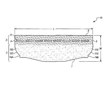
FIGS.1A, 1B, 2-10, and 14. FIGS. 1A and 1B illustrate a top plan view of
shingle 10. Shingle
has a width (w) and a length (/). Shingle 10 comprises a headlap portion 2, a
buttlap portion
3, a longitudinal front edge 7, a longitudinal rear edge 8, a lateral leading
edge 5, and a lateral
trailing edge 4. Lateral leading edge 5 may include a leading portion 74B and
a leading edge
projection 110. Lateral trailing edge 4 may include a first trailing portion
74A and a trailing
edge projection 100. When installed on a roof deck, as illustrated in FIGS. 7,
7B, and 8, the
headlap portion 2 of a previously installed shingle 10 is covered by at least
a portion of the
buttlap portion 3 of a subsequently installed shingle 10 and, as illustrated
in FIG. 7, the trailing
edge projection 100 of subsequently installed shingle 10 overlaps (i.e., side-
laps) a portion of a
previously installed shingle 10. It will further be appreciated that the
leading edge projection
110 of previously installed shingle 10 underlaps a portion of subsequently
installed shingle 10.
[00072] Referring to FIGS. 1A and 1B, trailing edge projection 100 has a
weather edge
103, a rear edge 104, a maximum breadth 101, and a height 102, and is situated
behind a trailing
portion 74A. Preferably, when shingle 10 is installed in accordance with the
instant invention, at
-17-
CA 02891785 2015-05-20
Attorney Docket No. 03398.000064.1
PATENT APPLICATION
least a portion of the weather edge 103 of trailing edge projection 100 is
exposed to weather and
the rear edge 104 of trailing edge projection 100 is covered by a subsequently
installed shingle in
a subsequent course of shingles. Preferably, the maximum breadth 101 may be
between 1 and 5
inches, and more preferably about 3 inches or about 2.5 inches or about 2
inches. Preferably, the
height 102 may be between 50% and 93% of the width (w) of shingle 10, and more
preferably
between 70% and 85% of shingle width (w) of shingle 10. In particular
preferred embodiments,
the height 102 may be about 66% or about 77% or about 79% or about 81% of the
width (w) of
shingle 10. Trailing edge projection 100 further has a variable breadth
(measured transversely
across the trailing edge projection 100 along a line parallel to the
longitudinal axis of shingle 10)
that increases toward the rear edge 104 of the trailing edge projection 100.
In this embodiment,
the trailing edge projection 100 has a curved portion with a convex profile
and a straight lateral
portion, which may have a constant breadth. The variable breadth of the
trailing edge projection
100 ranges from 0 inches to the maximum breadth 101. In another embodiment,
the trailing edge
projection may have a continuously curved and convex profile.
[000731 In another preferred embodiment, trailing edge projection 100 may
be situated
between a first trailing portion 74A and second trailing portion 73A. See,
e.g., FIG. 11, shingle
11.
[00074] Referring back to FIGS. lA and 1B, in a particularly preferred
embodiment, the
straight longitudinal rear edge 8 comprises a leading portion 814 and a
trailing portion 804
separated by a central portion 800, wherein the leading portion 814 consists
of the rear edge 114
of the leading edge projection 110 and the trailing portion 804 consists of
the rear edge 104 of
the trailing edge projection 100.
-18-
CA 02891785 2015-05-20
Attorney Docket No. 03398.000064.1
PATENT APPLICATION
1000751 To improve wind resistance, an edge of the side-lap shingle (i.e.,
the weather edge
103 of the trailing edge projection 100) should be designed in such a way as
to optimize the
aerodynamic performance of the shingle geometry, such that the propensity of
wind uplift at the
side-lap corner (or trailing projection 100) is highly reduced or eliminated.
An example may
comprise a side-lap edge (or a trailing projection 100) having a curved shape
that dissipates wind
impingements and greatly improves wind performance of a side-lap area.
1000761 Leading edge projection 110 has a projected edge 113, a rear edge
114, a
maximum breadth 111, and a height 112, and is situated behind a leading
portion 74B.
Preferably, the maximum breadth 111 may be between 1 and 5 inches, and more
preferably
about 3 inches or about 2.5 inches or about 2 inches. Preferably, height 112
is between 50% and
93% of the width (w) of shingle 10, and more preferably between 70% and 85% of
shingle width
(w) of shingle 10. In particular preferred embodiments, the height 102 may be
about 66% or
about 77% or about 79% or about 81% of the width (w) of shingle 10. In a
particularly preferred
embodiment, the maximum breadth 111 of the leading edge projection 110 is
about equal to the
maximum breadth 101 of the trailing edge projection 100 and the height 112 of
the leading edge
projection 110 is about equal to the height 102 of the trailing edge
projection 100. In a preferred
embodiment, the leading edge projection 110 may have a variable breadth. In a
particularly
preferred embodiment, the leading edge projection 110 has a shape that mirrors
the shape of
trailing edge projection 100. It is also contemplated that the leading edge
projection 110 may
have a continuously curved and concave profile (not shown). It is further
contemplated that the
leading edge projection 110 does not have a shape that mirrors the shape the
trailing edge
projection 100, e.g., the trailing edge projection 100 may have curved profile
or partially curved
profile and the leading edge projection 110 may have a rectangular shape.
-19-
CA 02891785 2015-05-20
Attorney Docket No. 03398.000064.1
PATENT APPLICATION
[00077] In another preferred embodiment, leading edge projection 110 may be
situated
between a first leading portion 74B and second leading portion 73B. See, e.g.,
FIG. 11, shingle
11.
1000781 Headlap portion 2 has a width measured laterally across shingle 10
that is less
than the width of the buttlap portion 3 measured laterally across shingle 10
defining a reduced-
width headlap. Preferably, the width of the headlap portion 2 may be between
15% and 50% of
the width (w) of the shingle 10, and more preferably about 25% or about 38% or
about 42% of
the width (w) of the shingle 10. Headlap portion 2 may include sealant strips
6.
[00079] As depicted in the embodiment shown in FIGS. 1A, 1B, 2-10, and 14,
shingle 10
of the invention may have a longitudinal front edge 7 that is non-straight.
However, the
longitudinal front edge of the shingle of the invention may be straight or may
have tabs spaced
apart by openings. See, e.g., shingles 11, 12, 13 depicted in FIGS. 11, 12,
and 13, respectively.
Referring back to FIGS. 1A, 1B, 2-10, and 14, shingle 10 of the invention may
have a non-
straight longitudinal front edge 7 that has a central horizontal portion 7x, a
left horizontal portion
7z, a right horizontal portion 7z', a first transition portion 7y, and a
second transition portion 7y',
wherein the central horizontal portion extends further away from the shingle
than the left
horizontal portion and the right horizontal portion (as identified as
dimension 7w), and wherein
the first transition portion is situated between the left horizontal portion
and the central
horizontal portion and the second transition portion is situated between the
central horizontal
portion and the right horizontal portion.
[00080] As depicted in FIGS. 1A, 1B, 2-10, and 14, shingle 10 may have an
undivided
buttlap. However, in other preferred embodiments, the buttlap portion may
include a plurality of
tabs spaced apart by a plurality of openings. The openings may have a
triangular shape or a
-20-
CA 02891785 2015-05-20
Attorney Docket No. 03398.000064.1
PATENT APPLICATION
trapezoidal shape. Referring to FIG. 11, shingle 11 has a buttlap portion that
includes a plurality
of tabs 1101 spaced apart by a plurality of triangular shaped openings 1102.
Referring to FIG.
12, shingle 12 has a buttlap portion that includes a plurality of tabs 1201
spaced apart by a
plurality of trapezoidal shaped openings 1202. It will be appreciated that the
non-parallel edges
of the trapezoidal shaped openings 1202 are formed by adjacent tabs 1201 and
the trapezoidal
shape of the openings narrow as the tabs 1201 extend away from the shingle 12.
However, the
openings may have an inverted trapezoidal shape, i.e., wherein the openings
widen as the tabs
1301 extend away from the shingle 13. See, e.g., FIG. 13, feature 1302.
Preferably, the tabs
may have a height (see, e.g., FIGS. 11, 12, 13 dimension Th) of about 1/2 inch
to about 2.5 inches,
and more preferably about 1.5 inches or about 2 inches. Furthermore, the
principles of the instant
invention may further be employed in laminated shingles (not shown).
[00081] An important feature of the present invention is the lateral
trailing edge 4
comprising at least one trailing abutting portion 74A and a trailing edge
projection 100 having a
weather edge 103, a rear edge 104, and a variable breadth that increases
toward the rear edge of
the trailing edge projection. As depicted in FIG. 14, in some embodiments, the
height of the
trailing edge projection 100 extends to the longitudinal rear edge 8 of the
shingle, wherein the
rear edge 104 of the trailing edge projection 100 forms the trailing portion
804 of the
longitudinal rear edge 8 of the shingle. See, e.g., FIG. 14, shingles 10, 12,
and 13. In other
embodiments, the height of the trailing edge projection 100 does not extend to
the longitudinal
rear edge 8 of the shingle, wherein the trailing edge projection 100 is
situated between a first
trailing abutting portion 74A and a second trailing abutting portion 73A. See,
e.g., FIG. 14,
shingle 11. In such embodiments, the rear edge 104 of the trailing edge
projection 100 does not
form a portion of a straight longitudinal rear edge.
-21-
CA 02891785 2015-05-20
Attorney Docket No. 03398.000064.1 PATENT
APPLICATION
[00082] FIG. 7 depicts a particularly preferred roofing system embodiment
of the present
invention, wherein three shingles 10A, 10B, 10C of the invention are installed
as they would be
applied to a roof deck in the same course, such that the trailing edge
projection 100 of a
subsequently installed shingle 10B overlaps a portion of a previously
installed shingle 10A
providing a first part of side-lap region 70 and the leading edge projection
110 of a previously
installed shingle 10A is underneath (or underlaps) a portion of a subsequently
installed shingle
10B providing a second part of side-lap region 70, wherein side-lap region 70
has a maximum
breadth 72. It will be appreciated that the maximum breadth 72 of the side-lap
region 70 is
equivalent to the sum of the maximum breadth 101 of the trailing edge
projection 100 and the
maximum breadth 111 of the leading edge projection 110. Preferably, the
maximum breadth 72
may be between 2 and 10 inches, and more preferably between 4 and 6 inches. In
particular
preferred embodiments, the maximum breadth 72 may be about 4 inches or about 5
inches or
about 6 inches.
[00083] Preferably, as depicted in FIG. 7, two shingles 10A and 10B of the
invention
partially abut each other at an abutment region 74. Referring back to FIG. 1A,
shingle 10 of the
invention has a trailing portion 74A that, when installed as in FIG. 7, abuts
a leading portion 74B
of a previously installed shingle in the same course to define the abutment
region 74.
[00084] Referring back to FIGS. 1A and 1B, the trailing portion 74A has a
height 474 and
the first leading portion 74B has a height 574. In a preferred embodiment,
heights 474, 574 of
first trailing portion 74A and first leading portion 74B, respectively, are
about equal and may be
between 0.5 and 4 inches, and more preferably are about I inch. In another
preferred
embodiment, heights 474, 574 may preferably be about 2.5 inches or about 3
inches. In yet
another preferred embodiment, heights 474, 574 are preferably about 2 inches.
-22-
CA 02891785 2015-05-20
Attorney Docket No. 03398.000064.1 PATENT
APPLICATION
1000851 In another preferred embodiment, as depicted in FIG. 15, two
shingles 11A and
11B of the invention partially abut each other at a first abutment region 74
and a second
abutment region 73. Referring to FIG. 11, shingle 11 of the invention has a
first trailing portion
74A that, when installed as in FIG. 15, abuts a first leading portion 74B of a
previously installed
shingle in the same course to define the abutment region 74. Shingle 11 of the
invention also has
a second trailing portion 73A that, when installed as in FIG. 15, abuts a
second leading portion
73B of a previously installed shingle in the same course to define the second
abutment region 73.
In a further preferred embodiment, heights 473, 573 of second trailing portion
73A and second
leading portion 73B, respectively, are about equal and may be between 0 and 4
inches, and more
preferably are 2 inches. In another preferred embodiment, heights 473, 573 are
preferably 1 Y2
inches. In a particularly preferred embodiment, heights 474, 574, 473, 573 are
about equal.
[00086] Preferably, shingle 10 of the invention further comprises an
alignment means. As
depicted in FIG. 7, shingles 10A, 10B may further include sealant strips 6
that operate as an
alignment means, wherein the sealant strips 6 on a previously installed
shingle 10A and the
sealant strips 6 on a subsequently installed shingle 10B create a straight
line that continues across
a same elevation alignment region 71 that spans adjacent shingles in the same
course. It will
further be appreciated that the abutment region 74 may provide alignment and
installation
assistance for the installer by acting as a fulcrum between the stationary
previously installed
shingle and the subsequent shingle to be installed.
1000871 FIG. 7 also depicts an alignment means between a shingle 10C of
the invention
in a subsequently installed course of shingles and two shingles 10A, 10B of
the invention in a
previously installed or first course of shingles. A third shingle 10C of the
invention is installed in
a subsequent course and overlaps the headlap portions 2 of the shingles 10A,
10B of the
-23-
CA 02891785 2015-05-20
Attorney Docket No. 03398.000064.1
PATENT APPLICATION
invention in the first course. The left and right horizontal portions, e.g.,
features 7z and 7z', of
the non-straight longitudinal front edge 7 of shingle 10C of the invention in
the subsequent
course align with the sealant strips 6 of a shingles 10A, 10B of the invention
in the first course.
In this embodiment, the left and right horizontal portions 7z, 7z' of the non-
straight longitudinal
front edge 7 are about flush with (or slightly extend over) the front edge of
the sealant strips 6 of
shingles 10A, 10B in the first course. Although the accompanying figures
depict sealant strips 6
arranged in clean straight lines, it will be appreciated that the actual
sealant strips placed onto the
shingles may not have a perfectly straight line appearance; however, the
alignment principles
disclosed herein are still applicable. Additional or alternative means of
aligning subsequently
installed shingles are also contemplated, such as alignment notches, slits, or
marks on the lateral
edges of subsequently installed shingles. Referring to FIG. 7A, shingles 10'A,
10'B, 10'C are
arranged in a fashion similar to that depicted in FIG. 7. Shingles 10'A, 10'B,
10'C further
comprise alignment slits 175, 176, wherein the alignment slits 175, 176 of a
subsequently
installed shingle 10'C align with the longitudinal rear edge 8 of previously
installed shingles
10'A, 10'B at alignment regions 75, 76.
[00088]
Referring to FIG. 7B, at a first trailing overlap region 90, the underside of
shingle
10D near the first trailing portion 74A of shingle 10D is sealed to sealant
strips 6 of shingle 10B.
The trailing edge projection 100 of shingle 10D may be sealed directly to
sealant strips 6 of a
previously installed shingle 10C at the second trailing overlap region 91. It
will be further
appreciated that, in preferred embodiments, subsequently installed shingles,
e.g., shingle 10E in
FIG. 7B, provide material overlap in the second trailing overlap region 91
such that three layers
of roofing material are present at this region of the ship-lap joint.
-24-
CA 02891785 2015-05-20
Attorney Docket No. 03398.000064.1
PATENT APPLICATION
[00089] Although the embodiments depicted in the accompanying figures have
sealant
strips 6 on the upper surface of the shingles, it is contemplated that,
altern' atively, sealant strips
may be affixed to the underside surface of the shingles proximate to the
longitudinal front edge 7
(not shown).
[00090] In a particularly preferred embodiment of the roofing system of the
invention,
shingles of the invention may be installed such that a minimum of 4 inches of
a side-lap overlap
exists at any water entry point._ However, it is contemplated that the minimum
side-lap overlap
may be 2 inches at any water entry point.
[00091] For one embodiment of the present invention, the shingle 10 may be
formed from
a fiberglass mat (not shown) with an asphalt coating on both sides of the mat.
If desired, the
present invention may also be used with shingles formed from organic felt or
other types of base
material, including but not limited to synthetic mats or synthetic
glass/hybrid mats having an
appropriate coating. Nonlimiting embodiments of coatings include asphalt and
modified
bituminous coatings based on atactic polypropylene (APP), styrene-butadiane-
styrene (SBS),
styrene-ethylene-butadiene-styrene (SEBS), amorphous polyalpha olefin (APAO),
thermoplastic
polyolefin (TPO), synthetic rubber, their combinations or other asphaltic
modifiers.
[00092] Referring to FIG. 1, the exposed outer surface or weather surface,
i.e., the buttlap
portion 3 of shingle 10 of the invention, may be coated with various types of
mineral granules to
protect the asphalt coating, to add color to shingle 10 of the invention and
to provide fire
resistance. For some applications, ceramic-coated mineral granules may be
disposed on the top
surface of the buttlap portion 3. Also, a wide range of mineral colors from
white and black to
various shades of red, green, brown and any combination thereof may be used to
provide a roof
having the desired color for shingle 10 of the invention. In other
embodiments, the entire outer
-25-
CA 02891785 2015-05-20
Attorney Docket No. 03398.000064.1
PATENT APPLICATION
surface of shingle 10 of the invention may be coated with any of the
aforementioned coatings. In
further embodiments, e.g., shingles having partially exposed headlap portions,
the headlap
portion 2 of shingle 10 of the invention may be coated with coatings having a
first shade of
granules that contrast with coatings having a second shade of granules applied
to the buttlap
portion 3 of shingle 10 of the invention. In these embodiments, the
contrasting colors of the
exposed headlap portion and the buttlap portion may create a perceived
increase in shingle depth.
This visual effect may be further enhanced by surfacing a portion of the front-
most part of the
buttlap portion, e.g., buttlap tabs, with a third shade of granules, and
further yet when the first
shade of granules is the darkest of the three shades and the third shade of
granules is the lightest
of the three shades. The underside of shingle 10 of the invention may be
coated with various
inert minerals with sufficient consistency to seal the asphalt coating.
[00093] An important feature of the present invention includes providing a
shingle having
a reduced-width headlap portion. For preferred embodiments of the present
invention, headlap
portion 2 may have a width that is about 25% or about 38% or about 42% of the
width (w) of
shingle 10 of the invention. However, as noted above, the headlap portion 2
may have a width
that is between 15% and 50% of the width (w) of shingle 10 of the invention.
[00094] Another important feature of the present invention includes
providing a shingle
having interlocking edges. For the embodiments of the present invention shown
in the instant
figures, the lateral trailing edge 4 and the lateral leading edge 5 of
adjacent installed shingles in
the same course partially overlap, partially underlap, and partially abut,
thereby forming an
interlocking edge between the adjacent installed shingles. However, other
forms of interlocking
edges are contemplated including, but not limited to, cutouts or holes in
various geometric
shapes and their combinations.
-26-
CA 02891785 2015-05-20
Attorney Docket No. 03398.000064.1
PATENT APPLICATION
[00095] Another important feature of the present invention includes
providing a shingle
with a side-lap edge (a trailing edge projection 100) having a variable
breadth that increases
toward a rear edge of the trailing edge projection. For the embodiment of the
present invention
shown in the instant figures, trailing edge projection 100 has a straight
portion 102x and a curved
portion 102y. However, other shapes and dimensions for the trailing edge
projection 100 that
dissipate wind impingements underneath the side-lap edge are contemplated and
within the scope
of the present invention, e.g., embodiments of the present invention may have
a trailing edge
projection having a continuously curved shape.
[00096] The reduced-width headlap portion and the unique shape and/or
dimensions of the
shingle of the present invention are desirable because they allow for an
improved utilization of
materials that are required to make the shingles. In preferred embodiments of
this invention, the
shingles and roof system of the present invention improve the material
utilization over
traditional, prior art 3-tab shingles preferably by at least 15% (less than
200 ft2 of material
needed for 100 ft2 of coverage), and more preferably by about 23% (about 186
ft2 of material
needed for 100 ft2 of coverage), or about 25% (about 181 ft2 of material sheet
needed for 100 ft2
of coverage), or about 29% (about 171 ft2 of material needed for 100 ft2 of
coverage).
[00097] The interlocking edges of the present invention are desirable for
improving
alignment upon installation and increased resistance to water infiltration.
[00098] The trailing edge projection 100 having a variable breadth that
increases toward a
rear edge of the trailing edge projection of the present invention is
desirable for increasing
resistance to wind impingements at or near the side-lap region.
[00099] The interlocking edges and the trailing edge projection 100 of the
present
invention are further desirable because they allow for improved weather
performance. In
-27-
CA 2891785 2017-03-07
preferred embodiments of this invention, the shingles and roofing system of
the present invention
reduce the % area of water infiltration over traditional, prior art 3-tab
shingles by at least 10%,
and more preferably by at least 15%, and yet more preferably by 20%. The %
area of water
infiltration is determined by the area of water wetting in the underlayment
upon testing per
Miami Dade TAS 100 wind-driven rain test.
EXAMPLE
[000100] Shingles having length (/) and width (w) dimensions of 36" x 12",
a reduced-
width headlap and a trailing edge projection in accordance with the invention
and a straight front
longitudinal edge were prepared by following a typical reduced-headlap shingle
production. A
4' x 4' test roof deck was constructed, wherein shingles of the invention were
installed in
accordance with the invention. The interlocking edge between adjacent shingles
in the same
course included a side-lap region having a maximum length of 6" and a first
abutment region and
a second abutment region each having a height of 2". The weather edge of the
side-lap included
a curved edge designed to provide wind dynamics for uplift reduction. A 4'x 4'
control roof
deck was constructed, wherein commercially available 3-tab shingles (Royal
Sovereign shingle
from GAF Corporation, Dallas, TX) were installed. Table 1 (below) lists the
amount of shingle
material needed per 100 ft2 based upon the deck construction calculation. As
will be
appreciated, the shingles of the invention have significantly better material
utilization with an
approximately 33% reduction in material usage comparing to the prior art,
control 3-tab shingles.
[000101] Both decks were then subjected to the Miami Dade TAS 100 wind-
driven rain
test, which includes wind-driven rain conditions at 35, 70, 90, and 110 mph
wind. After the test,
the shingles were removed and the water infiltration was observed. The amounts
of wet area
were recorded and estimated to within 5% of the total area, and listed in
Table 1 (below). As
-28-
CA 2891785 2017-03-07
will be appreciated, the shingles of the invention can significantly reduce
the amount of water
infiltration when compared to traditional, prior art 3-tab shingles.
Table 1
Sample Area needed to cover 100 ft2 % area
of water infiltration
Control: 3-tab shingles 240 20%
Test sample 160 5%
[000102] Although the present invention and its advantages have been
described in detail, it
should be understood that various changes, substitutions and alterations can
be made therein
without departing from the spirit and scope of the invention as defined by the
appended claims.
-29-