Note: Descriptions are shown in the official language in which they were submitted.
CA 02891848 2015-05-15
WO 2014/082818 PCT/EP2013/073010
Fluid Reservoir for an Aerosol Generation Device, Combination
of Fluid Reservoir and Primary Fluid Package, and Aerosol
Generation Device for Use with the Fluid Reservoir
Field of the Invention
The invention relates to a fluid reservoir which is
attachable to an aerosol generation device (nebuliser) for
guiding a fluid from a fluid container to the aerosol
generation device, a combination of the fluid reservoir and a
primary fluid package and an aerosol generation device which
is configured for use with the fluid reservoir.
Background Art
Aerosols for therapeutic purposes are generated with aerosol
generation devices. A conventional aerosol generation device
is disclosed, for example, in US-A-2011/0146670. The aerosol
generation device of this document comprises a fluid
reservoir for receiving a fluid (i.e., medicament) to be
nebulised, which is connected to the body of the device. The
fluid reservoir may be integrally connected to the device.
Alternatively, the fluid reservoir may be connected to the
device in such a manner that it can be coupled to and
uncoupled from the device.
Aerosols for therapeutic purposes generally have to meet high
requirements with regard to purity. Hence, if a fluid
reservoir that had been previously used for receiving a first
CA 02891848 2015-05-15
Printed:- 08/10/2014 DESCPAMD
-EP2013073010'
.2 =
fluid is to be reused with a second, different fluid, the
reservoir has to be thoroughly cleaned. However, for some
fluids even such a thorough cleaning procedure is not
sufficient. In this case, the used fluid reservoir has to be
discarded and a new fluid reservoir has to be used.
Nevertheless, there remains a risk that a used fluid
reservoir is accidentally reused, potentially causing a
contamination of the aerosol, thereby reducing the
effectiveness of the aerosol treatment or even posing a
health risk to a patient receiving the aerosol treatment.
US-A-2006/0213505 discloses an actuator for an inhaler for
delivering a medicament by inhalation, comprising: a main
body comprising a tubular member for receiving a canister
containing the medicament and having a valve stem extending
therefrom, a bottom surface at one end of the tubular member,
a mouthpiece for guiding the medicament to the mouth of a
user, and a nozzle block located in the bottom region of the
tubular member for receiving the valve stem of the canister
and delivering the medicament from the canister into the
mouthpiece.
Summary of the Invention
One object of the invention is to provide a fluid reservoir
which is attachable to an aerosol generation device for
guiding a fluid from a fluid container to the aerosol
generation device, allowing for an accidental reuse of the
fluid reservoir to be reliably prevented, thus minimising the
risk of contamination of the generated aerosol. Further, the
invention aims to provide a combination of the fluid
reservoir and a primary fluid package and an aerosol
generation device which is configured for use with the fluid
reservoir.
29/09/2014
AMENDED SHEET
CA 02891848 2015-05-15
,
;Printed: 98/10/2014, 'DESCPAMDµ
EP2013073010
2a
These goals are achieved by a fluid reservoir with the
technical features of claim 1, a combination of the fluid
reservoir and a primary fluid package with the technical
'features of claim 10 and an aerosol generation device with
!
=
the technical features of claim 12.
The invention provides a fluid reservoir which is attachable
to an aerosol generation device for guiding a fluid from a
fluid container to the aerosol generation device. The fluid
reservoir has an interface portion arranged at the fluid
reservoir for attaching the fluid reservoir to the aerosol
generation device. The interface portion has a locking
229/09/2014;
AMENDED SHEET
CA 02891848 2015-05-15
WO 2014/082818 PCT/EP2013/073010
3
element (safety lock element or closing seal element)
configured to non-detachably lock the fluid reservoir to the
aerosol generation device after attachment of the fluid
reservoir to the aerosol generation device. The locking
element is breakable to enable detachment of the fluid
reservoir from the aerosol generation device, while
reattachment to the aerosol generation device may be
disabled. The locking element may be configured so that,
after breaking thereof, reattachment of the fluid reservoir
to the aerosol generation device is disabled.
The fluid reservoir may comprise the fluid container. The
interface portion may be arranged at an end of the fluid
reservoir.
The locking element is configured so that, after attachment
of the fluid reservoir to the aerosol generation device, the
fluid reservoir cannot be detached from the aerosol
generation device without breaking the locking element.
Hence, the fluid reservoir is damaged after detachment
thereof from the aerosol generation device, i.e., after its
use. Therefore, an accidental reuse of the fluid reservoir
is reliably prevented, thus minimising any risk of
contamination of the aerosol and ensuring an effective
aerosol treatment.
The fluid reservoir may be configured so that the breaking of
the locking element destroys the fluid reservoir, i.e.,
renders it unusable. In particular, the locking element may
be configured so that, after breaking thereof, the fluid
reservoir is no longer attachable to the aerosol generation
device. In this way, an accidental reuse of the fluid
reservoir can be prevented in a particularly reliable manner.
The locking element may be configured so that the breaking
thereof leaves visible traces in the fluid reservoir. These
CA 02891848 2015-05-15
WO 2014/082818 PCT/EP2013/073010
4
traces will alarm a user that the fluid reservoir had been
used before. Thus, in this case, the locking element of the
interface portion may act as a tamper-evident feature.
The locking element may be configured to initially non-
detachably lock the fluid reservoir to the aerosol generation
device after attachment of the fluid reservoir to the aerosol
generation device. Herein, the term "initially" defines that
the locking element is configured to non-detachably lock the
fluid reservoir to the aerosol generation device in an
initial state, i.e., in a state in which the locking element
is intact, i.e., has not been broken.
The interface portion of the fluid reservoir may comprise one
or more attachment elements, such as pins or bolts, e.g.,
detent pins or index bolts, enabling attachment of the fluid
reservoir to the aerosol generation device. The one or more
attachment elements may be configured so that they can be
brought into engagement with an attachment portion, such as a
thread, threaded splines, a bayonet coupling or the like, of
the aerosol generation device.
The locking element of the interface portion of the fluid
reservoir may cooperate or interact with the one or more
attachment elements so that breaking the locking element
enables the one or more attachment elements to be disengaged
from the attachment portion of the aerosol generation device.
For example, the locking element may comprise one or more
flaps, tabs, lugs or the like arranged on the interface
portion and connected to the one or more attachment elements,
so that pulling or pressing these flaps, tabs, lugs etc.
breaks the locking element and brings the at least one
attachment element out of engagement with the attachment
portion of the aerosol generation device, thus enabling
detachment of the fluid reservoir from the device.
CA 02891848 2015-05-15
WO 2014/082818 PCT/EP2013/073010
Further, the locking element may be configured so that the
breaking thereof allows for the one or more attachment
elements to be removed from the interface portion of the
fluid reservoir, thereby enabling detachment of the fluid
reservoir from the device.
Beside the locking element, the interface portion may have a
sealing element configured to seal (plug, connect, drain off)
the fluid reservoir to the aerosol generation device after
attachment of the fluid reservoir to the aerosol generation
device. Therefore, a fluid can be guided without losses or
leak to the aerosol generation device.
The sealing element may comprise an elastic material, like
silicone, rubber, soft plastic and so on. The sealing
element may be formed as a gasket, a joint ring, a lip seal
or the like to connect the fluid reservoir with the sealing
element to the aerosol generation device.
The fluid reservoir may be formed of one or more parts. The
fluid reservoir may comprise the fluid container and an
adapter. The fluid container and the adapter may act
together as a fluid reservoir. In this case, the fluid is
guided by the adapter from the fluid reservoir to the aerosol
generation device. The adapter and/or the fluid container
may comprise one or more locking elements and/or sealing
elements as described above.
The adapter may have the interface portion of the fluid
reservoir for attaching the fluid reservoir to the aerosol
generation device.
Herein, the term "fluid container" refers to any type of
container in which a fluid, e.g., a fluid containing a
medicament or active compound, can be stored. The fluid
container may be made of various materials, for example,
plastic, such as polypropylene, glass, ceramic, metal or
CA 02891848 2015-05-15
WO 2014/082818 PCT/EP2013/073010
6
other suitable materials. For example, if the fluid
container is made of plastic, it can be manufactured in a
particularly simple manner, e.g., by injection moulding, a
blow-fill-seal process and the like.
The fluid container may be formed of one or more parts. The
fluid container may comprise one fluid chamber for containing
a fluid therein or a plurality of fluid chambers for
containing the same type or different types of fluid therein.
The fluid container may comprise two or more chambers with
solid substance, powder and/or fluid, which could be mixed in
the fluid container and/or in the fluid reservoir, e.g.,
directly before the use of the aerosol generation device. A
fluid mixture of the same kind is for example "Colistin" or
"Asperin".
The fluid container may have a substantially cylindrical
shape. Alternatively, the fluid container may have a
rectangular, square, triangular or other polygonal cross-
sectional shape.
The fluid container may comprise a base portion which allows
for the container to be placed on a flat surface. In this
case, the container can be filled with a fluid in a
particularly simple and convenient manner, for example from a
primary fluid package, a vial or the like.
The fluid container may be rigid in shape or flexible or
collapsible, e.g., in the form of a blister or pouch.
Further, also the fluid reservoir may be made of various
materials, such as plastic, e.g. polypropylene, glass,
ceramic, metal or other suitable materials. In particular,
the fluid reservoir may consist of different or same
materials in sections or in combinations, like sandwich
materials.
CA 02891848 2015-05-15
WO 2014/082818 PCT/EP2013/073010
7
The fluid reservoir of the invention may be used with any
type of aerosol generation device, aerosol delivery device,
aerosol inhalation device, medical aerosol device, aerosol
diagnostic device, aerosol prophylactic device, aerosol
therapeutic device, aerosol humidification device, a
humidifier/nebuliser for ventilation devices, or aerosol
therapy device. In particular, the aerosol generation device
may be a nebuliser, an atomiser, such as a humidifier, a
pneumatic nebuliser, a jet nebuliser, an electronic
nebuliser, an ultrasonic nebuliser, an electro-hydrodynamic
nebuliser, an electrostatic nebuliser, a membrane nebuliser,
a vibrating membrane nebuliser, e.g., an electronic vibrating
membrane nebuliser, or the like.
The fluid to be guided from the fluid reservoir, with and
without an adapter, to the aerosol generation device may be a
fluid for the generation of a pharmaceutical aerosol for the
delivery of an active compound. An active compound is a
natural, biotechnology-derived or synthetic compound or
mixture of compounds useful for the diagnosis, prevention,
management and/or treatment of a disease, condition or
symptom of an animal, in particular, a human.
Other terms which may be used as synonyms of the term "active
compound" include, for example, active ingredient, active
pharmaceutical ingredient, drug substance, diagnostic
material, drug, medicament or the like. The fluid can be of
a liquid, reconstructed solid substance or powder, solution,
suspension, nano-suspension, colloidal mixture or liposomal
formulation form.
The fluid reservoir of the invention is particularly
advantageous for use with multi-component fluids, in which
two or more components of the fluid have to be mixed
immediately before the aerosol treatment. The multi-component
fluids may be a mixture of fluid and fluid, of fluid and
powder as well as of fluid and solid substance. Generally,
CA 02891848 2015-05-15
WO 2014/082818 PCT/EP2013/073010
8
such multi-component fluids are especially sensitive to
contaminations in the fluid reservoir or the aerosol
generation device.
The active compound or compounds comprised in the fluid to be
guided from the fluid reservoir, with or without an adapter,
to the aerosol generation device may be a drug substance or a
medicament which is useful for the prevention, management,
diagnosis or treatment of any disease, symptom or condition
affecting the body, the skin, the body cavities, the abdomen,
the eyes, the intestine, the stomach, the nose, the sinuses,
the osteomeatal complex, the mouth, the trachea, the lungs,
the bronchia, the bronchioles, the alveoli and/or the
respiratory tract.
Among the active compounds which may be useful for serving
one of the purposes named previously and that may be used
together with the present invention are, for example,
substances selected from the group consisting of anti-
inflammatory compounds, anti-infective agents, antiseptics,
prostaglandins, endothelin receptor agonists,
phosphodiesterase inhibitors, beta-2-sympathicomimetics,
decongestants, vasoconstrictors, anticholinergics,
immunomodulators, mucolytics, anti-allergic drugs,
antihistaminics, mast-cell stabilizing agents, tumor growth
inhibitory agents, wound healing agents, local anaesthetics,
antioxidants, oligonucleotides, peptides, proteins, vaccines,
vitamins, plant extracts, cholinesterase inhibitors,
vasoactive intestinal peptide, serotonin receptor
antagonists, and heparins, glucocorticoids, anti-allergic
drugs, antioxidants, vitamins, leucotriene antagonists, anti-
infective agents, antibiotics, antifungals, antivirals,
mucolytics, decongestants, antiseptics, cytostatics,
immunomodulators, vaccines, wound healing agents, local
anaesthetics, oligonucleotides, xanthin derived agents,
peptides, proteins and plant extracts. Such compound may be
used in the form of a liquid, a powder, a solid substance, a
CA 02891848 2015-05-15
WO 2014/082818
PCT/EP2013/073010
9
suspension, a solution, a colloidal formulation (i.e.,
liposomal), etc. as well as a mixture thereof.
Examples of potentially useful anti-inflammatory compounds
are glucocorticoids and non-steroidal anti-inflammatory
agents such as betamethasone, beclomethasone, budesonide,
ciclesonide, dexamethasone, desoxymethasone, fluoconolone
acetonide, fluocinonide, flunisolide, fluticasone,
icomethasone, rofleponide, triamcinolone acetonide,
fluocortin butyl, hydrocortisone, hydroxycortisone-17-
butyrate, prednicarbate, 6-methylprednisolone aceponate,
mometasone furoate, dehydroepiandrosterone-sulfate (DHEAS),
elastane, prostaglandin, leukotriene, bradykinin antagonists,
non-steroidal anti-inflammatory drugs (NSAIDs), such as
ibuprofen including any pharmaceutically acceptable salts,
esters, isomers, stereoisomers, diastereomers, epimers,
solvates or other hydrates, prodrugs, derivatives, or any
other chemical or physical forms of active compounds
comprising the respective active moieties.
Examples of anti-infective agents, whose class or therapeutic
category is herein understood as comprising compounds which
are effective against bacterial, fungal, and viral
infections, i.e. encompassing the classes of antimicrobials,
antibiotics, antifungals, antiseptics, and antivirals, are
-
penicillins, including benzylpenicillins (penicillin-G-
sodium, clemizone penicillin, benzathine penicillin G),
phenoxypenicillins (penicillin V, propicillin),
aminobenzylpenicillins (ampicillin, amoxycillin,
bacampicillin), acylaminopenicillins (azlocillin,
mezlocillin, piperacillin, apalcillin), carboxypenicillins
(carbenicillin, ticarcillin, temocillin), isoxazolyl
penicillins (oxacillin, cloxacillin, dicloxacillin,
flucloxacillin), and amiidine penicillins (mecillinam);
CA 02891848 2015-05-15
WO 2014/082818 PCT/EP2013/073010
- cephalosporins, including cefazolins (cefazolin,
cefazedone); cefuroximes (cefuroxim, cefamandole, cefotiam),
cefoxitins (cefoxitin, cefotetan, latamoxef, flomoxef),
cefotaximes (cefotaxime, ceftriaxone, ceftizoxime,
cefmenoxime), ceftazidimes (ceftazidime, cefpirome,
cefepime), cefalexins (cefalexin, cefaclor, cefadroxil,
cefradine, loracarbef, cefprozil), and cefiximes (cefixime,
cefpodoxim proxetile, cefuroxime axetil, cefetamet pivoxil,
cefotiam hexetil), loracarbef, cefepim, clavulanic acid /
amoxicillin, Ceftobiprole;
- synergists, including beta-lactamase inhibitors, such as
clavulanic acid, sulbactam, and tazobactam;
- carbapenems, including imipenem, cilastin, meropenem,
doripenem, tebipenem, ertapenem, ritipenam, and biapenem;
- monobactams, including aztreonam;
- aminoglycosides, such as apramycin, gentamicin,
amikacin, isepamicin, arbekacin, tobramycin, netilmicin,
spectinomycin, streptomycin, capreomycin, neomycin,
paromoycin, and kanamycin;
- macrolides, including erythromycin, clarythromycin,
roxithromycin, azithromycin, dithromycin, josamycin,
spiramycin and telithromycin;
- gyrase inhibitors or fluroquinolones, including
ciprofloxacin, gatifloxacin, norfloxacin, ofloxacin,
levofloxacin, perfloxacin, lomefloxacin, fleroxacin,
garenoxacin, clinafloxacin, sitafloxacin, prulifloxacin,
olamufloxacin, caderofloxacin, gemifloxacin, balofloxacin,
trovafloxacin, and moxifloxacin;
- tetracyclins, including tetracyclin, oxytetracyclin,
rolitetracyclin, minocyclin, doxycycline, tigecycline and
aminocycline;
CA 02891848 2015-05-15
WO 2014/082818
PCT/EP2013/073010
11
- glycopeptides, inlcuding vancomycin, teicoplanin,
ristocetin, avoparcin, oritavancin, ramoplanin, and peptide
4;
- polypeptides, including plectasin, dalbavancin,
daptomycin, oritavancin, ramoplanin, dalbavancin, telavancin,
bacitracin, tyrothricin, neomycin, kanamycin, mupirocin,
paromomycin, polymyxin B and colistin;
- sulfonamides, including sulfadiazine, sulfamethoxazole,
sulfalene, co-trimoxazole, co-trimetrol, co-trimoxazine, and
co-tetraxazine;
- azoles, including clotrimazole, oxiconazole, miconazole,
ketoconazole, itraconazole, fluconazole, metronidazole,
tinidazole, bifonazol, ravuconazol, posaconazol,
voriconazole, and ornidazole and other antifungals including
flucytosin, griseofulvin, tolnaftal, naftifin, terbinafin,
amorolfin, ciclopiroxolamin, echinocandins, such as
micafungin, caspofungin, anidulafungin;
- nitrofurans, including nitrofurantoin and
nitrofuranzone;
- polyenes, including amphotericin B, natamycin, nystatin,
flucytosine;
- other antibiotics, including tithromycin, lincomycin,
clindamycin, oxazolindiones (linzezolids), ranbezolid,
streptogramine A+B, pristinamycin A+B, Virginiamycin A+B,
dalfopristin /quinupristin (Synercid), chloramphenicol,
ethambutol, pyrazinamid, terizidon, dapson, prothionamid,
fosfomycin, fucidinic acid, rifampicin, isoniazid,
cycloserine, terizidone, ansamycin, lysostaphin, iclaprim,
mirocin B17, clerocidin, filgrastim, and pentamidine;
CA 02891848 2015-05-15
WO 2014/082818
PCT/EP2013/073010
12
- antivirals, including aciclovir, ganciclovir, birivudin,
valaciclovir, zidovudine, didanosin, thiacytidin, stavudin,
lamivudin, zalcitabin, ribavirin, nevirapirin, delaviridin,
trifluridin, ritonavir, saquinavir, indinavir, foscarnet,
amantadin, podophyllotoxin, vidarabine, tromantadine, and
proteinase inhibitors, siRNA based drugs;
- antiseptics, including acridine derivatives, iodine-
povidone, benzoates, rivanol, chlorhexidine, quarternary
ammonium compounds, cetrimides, biphenylol, clorofene, and
octenidine;
- plant extracts or ingredients, such as plant extracts
from chamomile, hamamelis, echinacea, calendula, thymian,
papain, pelargonium, pine trees, essential oils, myrtol,
pinen, limonen, cineole, thymol, mentol, camphor, tannin,
alpha-hederin, bisabolol, lycopodin, vitapherole;
- wound healing compounds including dexpantenol,
allantoin, vitamins, hyaluronic acid, alpha-antitrypsin,
anorganic and organic zinc salts/compounds, salts of bismuth
and selen;
- interferones (alpha, beta, gamma), tumor necrosis
factors, cytokines, interleukines;
- immunmodulators including methotrexat, azathioprine,
cyclosporine, tacrolimus, sirolimus, rapamycin, mofetil;
mofetil-mycophenolate.
- cytostatics and metastasis inhibitors;
- alkylants, such as nimustine, melphanlane, carmustine,
lomustine, cyclophosphosphamide, ifosfamide, trofosfamide,
chlorambucil, busulfane, treosulfane, prednimustine,
thiotepa;
CA 02891848 2015-05-15
WO 2014/082818
PCT/EP2013/073010
13
- antimetabolites, e.g. cytarabine, fluorouracil,
methotrexate, mercaptopurine, tioguanine;
- alkaloids, such as vinblastine, vincristine, vindesine;
- antibiotics, such as alcarubicine, bleomycine,
dactinomycine, daunorubicine, doxorubicine, epirubicine,
idarubicine, mitomycine, plicamycine;
complexes of transition group elements (e.g. Ti, Zr, V,
Nb, Ta, No, W, Pt) such as carboplatinum, cis-platinum and
metallocene compounds such as titanocendichloride;
- amsacrine, dacarbazine, estramustine, etoposide,
beraprost, hydroxycarbamide, mitoxanthrone, procarbazine,
temiposide;
- paclitaxel, gefitinib, vandetanib, erlotinib, poly-ADP-
ribose-polymerase (PRAP) enzyme inhibitors, banoxantrone,
gemcitabine, pemetrexed, bevacizumab, ranibizumab.
Examples of potentially useful mucolytics are DNase, P2Y2-
agonists (denufosol), drugs affecting chloride and sodium
permeation, such as N-(3,5-Diamino-6-chloropyrazine-2-
carbony)-N'-{4-[4-(2,3-dihydroxypropoxy)-
phenyl]butyllguanidine methanesulfonate (PARION 552-02),
heparinoids, guaifenesin, acetylcysteine, carbocysteine,
ambroxol, bromhexine, tyloxapol, lecithins, myrtol, and
recombinant surfactant proteins.
Examples of potentially useful vasoconstrictors and
decongestants which may be useful to reduce the swelling of
the mucosa are phenylephrine, naphazoline, tramazoline,
tetryzoline, oxymetazoline, fenoxazoline, xylometazoline,
epinephrine, isoprenaline, hexoprenaline, and ephedrine.
CA 02891848 2015-05-15
WO 2014/082818 PCT/EP2013/073010
14
Examples of potentially useful local anaesthetic agents
include benzocaine, tetracaine, procaine, lidocaine and
bupivacaine.
Examples of potentially useful antiallergic agents include
the afore-mentioned glucocorticoids, cromolyn sodium,
nedocromil, cetrizin, loratidin, montelukast, roflumilast,
ziluton, omalizumab, heparinoids and other antihistamins,
including azelastine, cetirizin, desloratadin, ebastin,
fexofenadin, levocetirizin, loratadin.
Examples of potentially useful anticholinergic agents include
ipratropium bromide, tiotropium bromide, oxitropium bromide,
glycopyrrolate.
Examples of potentially useful beta-2-sympathicomimetic
agents include salbutamol, fenoterol, formoterol,
indacaterol, isoproterenol, metaproterenol, salmeterol,
terbutaline, clenbuterol, isoetarine, pirbuterol, procaterol,
ritodrine.
Examples of xanthine derived agents include theophylline,
theobromine, caffeine.
Antisense oligonucleotides are short synthetic strands of DNA
(or analogs) that are complimentary or antisense to a target
sequence (DNA, RNA) designed to halt a biological event, such
as transcription, translation or splicing. The resulting
inhibition of gene expression makes oligonucleotides
dependent on their composition useful for the treatment of
many diseases and various compounds are currently clinically
evaluated, such as ALN-RSVO1 to treat the respiratory
syncytical virus by, AVE-7279 to treat asthma and allergies,
TPI-ASM8 to treat allergic asthma, 1018-ISS to treat cancer.
Examples of potentially useful peptides and proteins include
antibodies against toxins produced by microorganisms,
CA 02891848 2015-05-15
WO 2014/082818 PCT/EP2013/073010
antimicrobial peptides such as cecropins, defensins,
thionins, and cathelicidins.
The fluid reservoir of the invention may be particularly
advantageously used with an aerosol generation device and a
ventilator which are intended and configured to remain in
connection with a patient for an extended period of time,
allowing for the repeated delivery of the same or different
types of aerosols. In this case, the accidental reuse of a
fluid reservoir, which had been previously used for the
delivery of a first type of fluid, for delivering a second
type of fluid can be reliably prevented. The attachment and
detachment of the fluid reservoir to and from the aerosol
generation device, respectively, allows the aerosol
generation device to stay in the ventilator circuit so as to
avoid an opening of the breathing circle tubes. The aerosol
generation device can remain in the ventilator circle and
therefore could be named "Inline" aerosol generation device
or nebuliser. The ventilator in this case may be a
respirator, intensive care unit, high frequency jet
ventilator, breathing assistance device, respiratory
assistant device, RADs, C-PAP, BI-PAP, V-PAP, NVPP,
controlled inhalation device (e.g., AKITA) or so on.
In one embodiment, the fluid reservoir is formed of a
plurality of parts. The fluid reservoir may comprise two,
three or more components. The fluid reservoir may comprise
the fluid container and an adapter, such as that described
above, and the fluid container may be detachably attached to
an interface portion of the adapter. In this case, the
adapter may be attachable to an aerosol generation device for
guiding a fluid from the fluid container to the aerosol
generation device.
In particular, the adapter may have the interface portion of
the fluid reservoir for attaching the fluid reservoir to the
aerosol generation device. The adapter may have two or more
CA 02891848 2015-05-15
WO 2014/082818 PCT/EP2013/073010
16
interface portions arranged at different positions (ends) of
the adapter. The adapter may have a first interface portion
arranged at a first end of the adapter for attaching the
adapter to the aerosol generation device and a second
interface portion arranged at a second end of the adapter for
attaching the adapter to the fluid container. The second end
of the adapter may be arranged so that it lies opposite to
the first end of the adapter.
For example, the second interface portion of the adapter may
be provided with a threaded section, a bayonet coupling or
the like for attachment to the fluid container. The fluid
container may be configured so that it cannot be attached to
the aerosol generation device without the adapter.
In the embodiment detailed above, the fluid container may be
filled with a fluid or a combination or mixture of different
fluids, for example from one or more primary fluid packages.
Subsequently, the adapter may be attached to the fluid
container. In this case, the adapter and the fluid container
in combination may form a fluid tight space containing the
fluid or mixture of fluids and work as a fluid reservoir.
The fluid container having the adapter attached thereto can
be attached to the aerosol generation device for guiding the
fluid from the fluid container to the device.
After delivery of the fluid to the aerosol generation device,
the fluid reservoir can be detached from the device only if
the locking element is broken, so that an accidental reuse of
the fluid reservoir in a following aerosol treatment is
reliably prevented.
,
The fluid container may be provided together with the
adapter, e.g., so that the adapter and the fluid container
are arranged together in a single package, or together with
the aerosol generation device, e.g., so that the aerosol
CA 02891848 2015-05-15
WO 2014/082818 PCT/EP2013/073010
17
generation device and the fluid reservoir (fluid container
and adapter) are arranged together in a single package.
In another embodiment, the fluid container and/or the adapter
is formed integrally with the fluid reservoir. Due to this
integral structure, it can be ensured that the fluid
container and/or the adapter have to be discarded together
with the fluid reservoir after the first use thereof.
Specifically, a fluid reservoir, including a fluid container
and an adapter, which has been detached from the aerosol
generation device has a broken locking element, preventing an
accidental reuse of the fluid reservoir and also of the fluid
container and/or the adapter which is integrally formed
therewith. Thus, also any contamination of the fluid
container and/or the adapter can be reliably and efficiently
prevented.
This integral fluid reservoir, including the fluid container
and the adapter, may be made of plastic, such as
polypropylene, and can be manufactured, for example, by
injection moulding. In this way, the integral fluid
reservoir can be fabricated in a particularly simple manner.
The fluid reservoir may further comprise a lid element for
sealing the fluid reservoir or the fluid container. In this
case, the fluid reservoir or the fluid container may be
filled with a fluid or a combination or mixture of different
fluids and the reservoir or the container may subsequently be
sealed by the lid element, in order to prevent any
contamination of the fluid or mixture of fluids due to
contact with the surrounding environment.
The lid element may be configured so that, after sealing the
fluid reservoir or the fluid container, the lid element
cannot be detached from its sealing position without breaking
the lid element, the fluid reservoir and/or the fluid
container. In this way, a reopening of the fluid reservoir
CA 02891848 2015-05-15
WO 2014/082818 PCT/EP2013/073010
18
or the fluid container after it has been filled, causing the
risk of contamination of the fluid or mixture of fluids
contained therein, can be reliably prevented. Further, if a
sealed fluid reservoir or fluid container is opened by
accident, the lid element, the fluid reservoir and/or the
fluid container will be broken, providing a clear indication
to a user of the reopening of the reservoir or container,
thus acting as a tamper-evident feature.
In one embodiment, the locking element is configured so that
it has to be manually broken before detachment of the fluid
reservoir from the aerosol generation device. Herein, the
term "manually" means directly, i.e., by the direct
application of a manual force. The locking element has to be
broken first, e.g., by pulling or pressing one or more tabs,
flaps, lugs or the like arranged on the interface portion of
the fluid reservoir, as detailed above, in order to enable
detachment of the fluid reservoir from the aerosol generation
device. No detachment of the fluid reservoir from the
aerosol generation device is possible before the locking
element is manually broken.
This configuration of the locking element has the advantage
that the requirement of manually breaking the locking element
will directly indicate to a user the disposable nature of the
fluid reservoir and may prompt him to discard the fluid
reservoir immediately after use or at the latest before
reuse.
The locking element may be configured so that the locking
element is automatically broken when detaching the fluid
reservoir from the aerosol generation device. Thus, the
process of detaching the fluid reservoir from the device
automatically breaks the locking element. Herein, the term
"automatically" means that no separate action is required to
break the locking element, but that the locking element is
broken in the detachment process of the fluid reservoir.
CA 02891848 2015-05-15
WO 2014/082818 PCT/EP2013/073010
19
Breaking the locking element may provide audible or visual
feedback to the operator, caregiver or patient that the fluid
reservoir and/or fluid container are no longer usable.
In this case, since no separate step of breaking the locking
element is required, the fluid reservoir can be detached from
the aerosol generation device in a particularly simple
manner.
One or more interface portions of the fluid reservoir, the
fluid container, the adapter and/or the aerosol generation
device may further have one or more valve elements for
regulating fluid flow from the fluid reservoir into the
aerosol generation device.
In particular, the interface portion of the fluid reservoir
for attaching the fluid reservoir to the aerosol generation
device may have a valve element for sealing an end of the
fluid reservoir and regulating the fluid flow to the aerosol
generation device. The valve element may be configured so
that it can be opened by a corresponding opening element,
such as a thorn, a hollow needle, a collar, a conduit or the
like, provided in the aerosol generation device.
By using a valve element for regulating fluid flow from or
through the fluid reservoir, the fluid flow can be controlled
in a particularly accurate and precise manner, thus enabling
aerosol delivery with a high degree of precision. The valve
element may be configured so that it is normally, i.e., if no
external force is applied thereto, in a closed state, thus,
for example, sealing the end of the fluid reservoir. The
valve element may be, for example, a ball valve, a valve
diaphragm or the like.
The interface portion of the fluid reservoir for attaching
the fluid reservoir to the aerosol generation device may
further have a wall element (septum) sealing an end of the
CA 02891848 2015-05-15
WO 2014/082818 PCT/EP2013/073010
fluid reservoir. The wall element may have at least one
weakened portion, such as a predetermined breaking point or
line or a pull linkage, facilitating at least partial
breaking of the wall element. In this case, the wall element
may be at least partially broken by an opening element of the
aerosol generation device, such as a thorn, a hollow needle,
a collar, a conduit or the like, enabling fluid to flow from
the fluid container through the fluid reservoir to the
aerosol generation device through the opening element.
The invention further provides a combination of the fluid
reservoir and a primary fluid package, wherein the primary
fluid package has at least one chamber containing a fluid
therein. Herein, the term "primary fluid package" defines
any type of package, container, blister, pouch, ampoule, vial
or reservoir in which a fluid, such as a fluid containing a
medicament, drug, substance or active compound, can be
stored. The at least one chamber forms a fluid-tight space.
The primary fluid package can be made of various materials,
for example, plastic, such as polypropylene, glass, ceramic,
metal or other suitable materials. In particular, the
primary fluid package may also consist of different or same
materials in sections or in combinations, like sandwich
materials. For example, a glass primary fluid package can be
sealed with a plastic seal or different areas of the primary
fluid package can be made of different plastics which are
accordingly selected depending on their use at the
corresponding primary fluid package areas.
The primary fluid package may be manufactured, for example,
by a blow-fill-seal (BFS) process. In this way, the primary
fluid package can be fabricated in a particularly simple and
efficient manner.
The primary fluid package is configured so that it can be
opened by removing a closure element from the package,
CA 02891848 2015-05-15
WO 2014/082818 PCT/EP2013/073010
21
thereby allowing the fluid packed in the at least one chamber
to flow out of the package. The closure element may be
configured so that it has to be torn or twisted off from the
primary fluid package in order to open the package. In
particular, the closure element may be a toggle closure or
the like.
In use, the primary fluid package is opened and the fluid
contained therein is filled into the fluid container or the
fluid reservoir. Subsequently, if a separate fluid container
is used, an adapter, such as those described above, may be
attached to the container containing the fluid therein. The
fluid container with the adapter attached thereto or the
integral fluid reservoir, including the fluid container and
the adapter as described above, is attached to the aerosol
generation device for guiding the fluid from the fluid
reservoir to the device. By providing the fluid reservoir
and the primary fluid package in combination, it can be
ensured that a suitable type of fluid reservoir is used for
the fluid contained in the primary fluid package.
The primary fluid package may have two or more chambers, each
chamber containing the same or a different fluid therein.
Such a configuration is particularly advantageous for the
case of multi-component fluids (drugs, medicaments, etc.), in
which two or more fluid components have to be mixed or
combined immediately before the aerosol treatment, for
example, if the fluids in a mixed or combined state are not
stable over a longer time period.
The primary fluid package may further comprise at least one
chamber comprising a solid material (e.g., a solid medicament
or drug), such as a dry powder, lyophilized powder, a
granular material, a tablet or the like, which is to be mixed
with the fluid or fluids contained in the remaining chamber
or chambers.
CA 02891848 2015-05-15
=
Printed:' 08/10/2014 DESCPAMD.
E P201307301 0
22
The primary fluid package may be configured so that the
plurality of chambers are sealed by a single closure element,
such as a toggle closure. In this way, by removing the
single closure element, all the chambers are opened, thus
ensuring the correct mixing ratio of the different fluids and
minimising the risk that one or more of the different fluids
might be administered separately.
As has been discussed in detail above, the fluid reservoir of
the invention is particularly advantageous for use with such
multi-component fluids.
The fluid reservoir and the primary fluid package may be
arranged together in a single package, for example, a pouch.
The package may be made, for example, from plastic, such as
polyethylene or the like; e.g., from a plastic bag.
By arranging the fluid reservoir and the primary fluid
package together in a single package it can be ensured that
the corresponding fluid reservoir and primary fluid package .
are used together in one aerosol treatment. Thus, the
accidental use of a wrong fluid reservoir for a particular
fluid or the use of the fluid in the primary fluid package
without any fluid reservoir can be reliably avoided.
The fluid container, the primary fluid package and the
adapter may be provided together, e.g., so that the fluid
container, the primary fluid package and the adapter are
arranged together in a single package, such as a pouch.
The invention further provides an aerosol generation device
which is configured for use with the fluid reservoir. The
aerosol generation device has an attachment portion for
receiving the interface portion of the fluid reservoir. The
aerosol generation device comprises the fluid reservoir.
The attachment portion may comprise an engagement section,
such as a thread, threaded splines, a bayonet coupling or the
,
3
29/09/2014
AMENDED SHEET
CA 02891848 2015-05-15
WO 2014/082818 PCT/EP2013/073010
23
like, for enabling attachment of the interface portion of the
fluid reservoir thereto. The engagement section may comprise
at least one detent element configured to lock the locking
element of the fluid reservoir.
The attachment portion may have an override section. In
particular, the attachment portion may be configured so that,
after attachment of the fluid reservoir to the aerosol
generation device, at least a part of the locking element of
the fluid reservoir is arranged in the override section. In
this state, the override section allows the fluid reservoir
to rotate freely relative to the attachment portion, e.g.,
about the longitudinal axis of the fluid reservoir. However,
this rotational movement does not induce any axial movement
of the fluid reservoir relative to the attachment portion.
Hence, the fluid reservoir is securely and initially non-
detachably locked to the attachment portion.
The attachment portion of the aerosol generation device may
have at least one detachment or release element, such as a
wedge structure or the like, which automatically breaks the
locking element when the fluid reservoir is detached, e.g.,
unscrewed, from the attachment portion of the aerosol
generation device.
Further, the detachment or release element may comprise one
or more openings, cut-outs, recesses or the like which are
arranged so as to receive at least a part of the locking
element of the fluid reservoir when the fluid reservoir is
attached to the aerosol generation device. In this case,
when the fluid reservoir is detached, e.g., unscrewed, from
the attachment portion, the part of the locking element is
retained by the one or more openings, cut-outs, recesses or
the like, so that the locking element is automatically broken
by the detachment or release element in the process of
detaching the fluid reservoir from the aerosol generation
device.
CA 02891848 2015-05-15
WO 2014/082818 PCT/EP2013/073010
24
The aerosol generation device is configured so that a fluid
can be supplied thereto only by use of the fluid reservoir.
In particular, the aerosol generation device does not have an
integral fluid reservoir for receiving a fluid to be
nebulised.
The aerosol generation device of the invention may be any
type of aerosol generation device, such as a nebuliser, an
atomiser, such as a humidifier, a pneumatic nebuliser, a jet
nebuliser, an electronic nebuliser, an ultrasonic nebuliser,
an electrode-hydrodynamic nebuliser, an electrostatic
nebuliser, a membrane nebuliser, a vibrating membrane
nebuliser, e.g., an electronic vibrating membrane nebuliser,
a humidifier/nebuliser for ventilation devices, or the like.
The aerosol generation device according to the invention
provides the advantageous effects already described in detail
above for the fluid reservoir of the invention. In
particular, the aerosol generation device of the invention
allows for a contamination of the generated aerosol to be
reliably prevented, thereby ensuring an effective aerosol
treatment.
The aerosol generation device may further have an opening
element, such as a thorn, a hollow needle, a collar, a
conduit or the like, for opening the interface portion of the
fluid reservoir and guiding the fluid from the fluid
reservoir into the interior of the aerosol generation device.
The opening element may be provided with a sharp edge or tip
portion, such as a blade element or the like, at a top
portion thereof, in order to facilitate opening of the
interface portion of the fluid reservoir and draining of the
fluid from the fluid reservoir. Such a configuration is
particularly advantageous for use with a fluid reservoir with
an interface portion having a wall element sealing the end of
the fluid reservoir, as described above.
CA 02891848 2015-05-15
WO 2014/082818 PCT/EP2013/073010
The opening element of the aerosol generation device may be
configured for opening a valve element, such as a ball valve,
a valve diaphragm or the like, provided in the interface
portion of the fluid reservoir for regulating fluid flow
through the fluid reservoir into the aerosol generation
device.
The opening element may have a substantially cylindrical
shape. A conduit, channel or the like may be provided in the
opening element for guiding fluid from the fluid reservoir
into the interior of the aerosol generation device. The
conduit or channel may have a substantially cylindrical
shape. Alternatively, the opening element and/or the conduit
or channel may have a rectangular, square, triangular or
other polygonal cross-sectional shape. A substantially
cylindrical shape of the opening element provides the
advantage of enabling a particularly uniform opening of the
fluid reservoir, thus allowing for a steady opening process.
A substantially cylindrical shape of the conduit or channel
offers the advantage of enabling a particularly homogeneous
flow of the fluid through the opening element into the
aerosol generation device.
The attachment portion of the aerosol generation device may
be provided with a valve element, such as a ball valve or the
like, for regulating fluid flow through the fluid reservoir
into the interior of the aerosol generation device. In this
way, the fluid flow into the device can be controlled with a
particularly high degree of accuracy and precision, thereby
ensuring a high aerosol dosage precision.
The aerosol generation device may further comprise a
protective cap or lid for closing or sealing the attachment
portion. In this way, a contamination of the aerosol
generation device by ambient air entering the device can be
reliably prevented when the device is not in use. The
protective cap or lid may be attached to the aerosol
CA 02891848 2015-05-15
WO 2014/082818 PCT/EP2013/073010
26
generation device, e.g., by a hinge, integrally formed with
the aerosol generation device or provided as a separate
entity. The structure of the protective cap may be similar
to that of the fluid reservoirs described above. In
particular, the structure of an interface portion of the
protective cap may be the same as that of the interface
portions of these fluid reservoirs. The protective cap may
differ from these fluid reservoirs in that it has a wall
sealing the end of the protective cap so as to enable a
reliable closing and sealing of the attachment portion.
The attachment portion of the aerosol generation device may
have at least one opening (cut-out, recess) which is arranged
so as to be closed by at least a part of the interface
portion of the fluid reservoir after attachment of the fluid
reservoir to the aerosol generation device. Further, the
aerosol generation device may have a plurality of such
openings which are arranged so as to be closed by at least a
part of the interface portion after the fluid reservoir has
been attached to the device. The at least one opening may be
formed in a side wall and/or a bottom wall of the attachment
portion.
By providing such an at least one opening in the attachment
portion of the aerosol generation device, an accidental use
or misuse of the device without the fluid reservoir in place
can be particularly reliably prevented. Specifically, due to
the presence of the at least one opening, the attachment
portion of the aerosol generation device cannot store a
fluid, since the fluid would drain from the at least one
opening. The at least one opening in the attachment portion
of the aerosol generation device may be formed as one or more
gaps, spaces, holes or the like. By attaching the fluid
reservoir to the aerosol generation device, the at least one
opening is closed by at least a part of the interface portion
of the fluid reservoir, thereby enabling the supply of fluid
to the aerosol generation device.
CA 02891848 2015-05-15
Printed: 08/10/2014 'DESCPAMDµ
EP2013073010
27
The aerosol generation device of the invention comprises the
fluid reservoir of the invention.
Brief Description of the Drawings
Hereinafter, non-limiting examples of the invention are
explained with reference to the drawings, in which:
Figs. 1(a) to (d) show schematic views of a fluid reservoir
according to a first embodiment of the present
invention, wherein Fig. 1(a) is a perspective
view of the fluid reservoir, Fig. 1(b) is a
bottom view of the fluid reservoir, Fig. 1(c)
is a top view of the fluid reservoir and Fig.
1(d) is a cross-sectional view of the fluid
reservoir in a plane parallel to a direction
of fluid flow through the fluid reservoir;
Figs. 2(a) to (d) show schematic views of a portion of an
aerosol generation device according to a first
embodiment of the present invention, wherein
Fig. 2(a) is a perspective view of the portion
of the aerosol generation device, Fig. 2(b) is
a cross-sectional view of the portion of the
aerosol generation device in a plane parallel
to a direction of aerosol flow, Fig. 2(c) is a
side view of the portion of the aerosol
generation device with the fluid reservoir of
Figs. 1(a) to (d) attached thereto and Fig.
2(d) is a cross-sectional view of the portion
of the aerosol generation device with the
fluid reservoir of Figs. 1(a) to (d) attached
thereto, in a plane parallel to the direction
of aerosol flow;
Figs. 3(a) to (d) show schematic views of a portion of an
aerosol generation device according to a
4 AMENDED SHEET
29/09/2014
CA 02891848 2015-05-15
WO 2014/082818
PCT/EP2013/073010
28
second embodiment of the present invention and
a fluid reservoir according to a second
embodiment of the present invention, wherein
Fig. 3(a) is a perspective view of the fluid
reservoir without cap, Fig. 3(b) is a
perspective view of an attachment portion of
the aerosol generation device, Fig. 3(c) is a
perspective view of the portion of the aerosol
generation device with the fluid reservoir
attached thereto and Fig. 3(d) is a cross-
sectional view of the portion of the aerosol
generation device with the fluid reservoir
attached thereto, in a plane parallel to the
direction of aerosol flow;
Figs. 4(a) to (d) show
schematic views of a protective cap
for closing or sealing an attachment portion
of an aerosol generation device, wherein Fig.
4(a) is a perspective view of the protective
cap, Fig. 4(b) is a bottom view of the
protective cap, Fig. 4(c) is a top view of the
protective cap and Fig. 4(d) is a cross-
sectional view of the protective cap in a
plane parallel to a longitudinal direction of
the protective cap;
Figs. 5(a) and (b) show schematic views of a portion of the
aerosol generation device according to the
first embodiment of the present invention
shown in Figs. 2(a) to (d) having the
protective cap shown in Figs. 4(a) to (d)
attached thereto, wherein Fig. 5(a) is a
perspective view of the portion of the aerosol
generation device and Fig. 5(b) is a cross-
sectional view of the portion of the aerosol
generation device in a plane parallel to a
direction of aerosol flow;
CA 02891848 2015-05-15
WO 2014/082818
PCT/EP2013/073010
29
Fig. 6 shows a
schematic view of an adapter and a
primary fluid package which are arranged
together in a pouch;
Figs. 7(a) to (d) show
schematic views illustrating the
process of supplying fluid to an aerosol
generation device according to a third
embodiment of the present invention using the
adapter and the primary fluid package of Fig.
6, wherein Fig. 7(a) illustrates the step of
filling a fluid container with fluid from the
primary fluid package , Fig. 7(b) is a
perspective view of the fluid container with
the adapter attached thereto, Fig. 7(c)
illustrates the step of attaching the fluid
reservoir, formed by the fluid container and
the adapter, to the aerosol generation device
and Fig. 7(d) is a cross-sectional view of the
aerosol generation device with the fluid
reservoir attached thereto in a plane parallel
to a direction of aerosol flow; and
Figs. 8(a) and (b) show schematic views of a portion of an
aerosol generation device according to a
fourth embodiment of the present invention
having a fluid reservoir according to a fourth
embodiment of the present invention attached
thereto, wherein Fig. 8(a) is a side view of
the portion of the aerosol generation device
and Fig. 8(b) is a cross-sectional view of the
portion of the aerosol generation device in a
plane parallel to a direction of aerosol flow.
CA 02891848 2015-05-15
WO 2014/082818 PCT/EP2013/073010
Detailed Description of Currently Preferred Embodiments
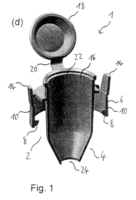
Figs. 1(a) to (d) show schematic views of a fluid reservoir 1
according to a currently preferred first embodiment of the
invention.
The fluid reservoir 1 shown in Fig. 1 has an interface
portion 2 arranged at an end 4 of the fluid reservoir 1 for
attaching the fluid reservoir 1 to an aerosol generation
device, which will be described later. The interface portion
2 comprises a collar 6 with a pair of pins 8, e.g., detent
pins or locking pins, extending from an inner surface
thereof. Each of portions 10 of the collar 6 on which the
pins 8 are provided is connected to the remainder of the
collar 6 through two weakened portions 12, facilitating
removal of the collar portions 10 from the collar 6.
Further, each of the collar portions 10 is integrally formed
with a flap or tab 14 extending upwards from the collar
portions 10 in an axial direction of the fluid reservoir 1,
i.e., in a direction of fluid flow in the fluid reservoir 1.
The pins 8 provided on the collar 6 of the fluid reservoir I
can be brought into engagement with a corresponding
engagement section, such as a thread, threaded splines, a
bayonet coupling or the like, provided on an attachment
portion of the aerosol generation device so as to initially
non-detachably lock the fluid reservoir 1 to the aerosol
generation device after attachment of the fluid reservoir 1
thereto, as will be described in detail below.
The portions 10 of the collar 6 on which the pins 8 are
provided can be removed from the collar 6 by pulling the
flaps or tabs 14 outwards in a radial direction of the fluid
reservoir 1, thereby breaking or tearing the weakened
portions 12. In this way, the collar portions 10 and thus
also the pins 8 can be removed from the collar 6, thereby
breaking the lock and enabling detachment of the fluid
CA 02891848 2015-05-15
WO 2014/082818 PCT/EP2013/073010
31
reservoir 1 from the aerosol generation device. Hence, the
pins 8, the collar portions 10, the weakened portions 12 and
the flaps or tabs 14 in combination form a breakable locking
element.
The fluid reservoir 1 according to the first embodiment of
the invention is integrally formed with a fluid container 16.
The fluid container 16 comprises a lid element 18 for sealing
the fluid container 16. The lid element 18 is connected to a
top portion of the fluid reservoir 1 by a resilient hinge 20.
The lid element 18 can be secured to an opening 22 of the
fluid container 16 by a snap fit or the like, thereby sealing
the fluid container 16.
The end 4 of the fluid reservoir 1 has an opening 24 which is
suitable for receiving a valve element (not shown), such as a
ball valve, a valve diaphragm or the like, for regulating
fluid flow through the fluid reservoir 1 into the aerosol
generation device. Alternatively, the opening 24 provided at
the end 4 of the fluid reservoir 1 may remain open.
Next, the use of the fluid reservoir 1 for supplying a fluid
to an aerosol generation device is described with reference
to Figs. 2(a) to (d), which show schematic views of a portion
50 of an aerosol generation device according to a currently
preferred first embodiment of the invention.
The aerosol generation device has an attachment portion 52
for receiving the interface portion 2 of the fluid reservoir
1. The attachment portion 52 has an engagement section 54,
such as a thread, threaded splines or a bayonet coupling,
configured to receive the pins 8 provided on the interface
portion 2 of the fluid reservoir 1.
The attachment portion 52 has an override section 56. As is
shown in Fig. 2(a), the override section 56 is formed by a
portion of the engagement section 54 in which a threaded
CA 02891848 2015-05-15
WO 2014/082818 PCT/EP2013/073010
32
spline passes into a circumferential groove 61 extending
along the circumference of the attachment portion 52. In
particular, the engagement section 54 is configured so that,
when screwing the fluid reservoir 1 onto the attachment
portion 52, the pins 8 of the fluid reservoir 1 are guided by
a guiding groove 57 of the engagement section 54 into the
circumferential groove 61. Once the pins 8 have entered into
the circumferential groove 61, the fluid reservoir 1 is
freely rotatable relative to the attachment portion 52 about
the longitudinal axis of the fluid reservoir 1, but this
rotational movement does not induce any axial movement of the
fluid reservoir 1 relative to the attachment portion 52.
Hence, the fluid reservoir 1 is securely and initially non-
detachably locked to the attachment portion 52.
The aerosol generation device of the first embodiment, a
portion 50 of which is shown in Figs. 2(a) to (d), is a
vibrating membrane nebuliser. The device comprises a
membrane space 58 in which the membrane 59 is arranged.
Fluid is guided from the attachment portion 52 through a
conduit or channel 60 to the membrane 59, where it is
nebulised so as to generate an aerosol. The generated
aerosol is supplied to a patient via a conduit or channel 62.
In one embodiment, the conduit or channel 62 is coupled to a
ventilator tube system that is connected to the patient. In
an alternative embodiment, the conduit or channel 62 may be
connected to or formed as a mouthpiece or a face mask or a
nose mask or an endotracheal tube with or without a valve to
connect the aerosol generation device directly to a patient.
The attachment portion 52 of the aerosol generation device
has at least one opening 64 provided in the side wall or the
bottom wall thereof, as shown in Figs. 2(a) to (c). This
opening 64 prevents a direct filling of the attachment
portion 52 with a fluid, since fluid supplied directly to the
attachment portion 52 would flow out of the device through
CA 02891848 2015-05-15
WO 2014/082818 PCT/EP2013/073010
33
the at least one opening 64. Hence, no fluid can be stored
in the attachment portion 52. In this way, a use of the
aerosol generation device without the fluid reservoir 1 can
be reliably prevented.
In the following, the steps for supplying a fluid to the
aerosol generation device using the fluid reservoir 1 of the
first embodiment with and without a valve element provided in
the opening 24 are described.
If the opening 24 of the fluid reservoir 1 is left open,
i.e., no valve element is provided in the opening 24, the
fluid reservoir 1 is first attached to the attachment portion
52 of the aerosol generation device.
Specifically, the pins 8 of the interface portion 2 of the
fluid reservoir 1 are inserted into the engagement section 54
of the attachment portion 52 and the fluid reservoir 1 is
screwed onto the attachment portion 52 (Figs. 2(c) and (d)).
Once the pins 8 have entered into the circumferential groove
61 of the override section 56 of the engagement section 54,
the override section 56 prevents the pins 8 from moving
upwards in the axial direction of the attachment portion 52,
so that the fluid reservoir 1 cannot be unscrewed from the
attachment portion 52. In this state, the pins 8 can move
freely in the circumferential groove 61, so that the fluid
reservoir 1 is freely rotatable relative to the attachment
portion 52 about the longitudinal axis of the fluid reservoir
1. However, this rotational movement does not induce any
axial movement of the fluid reservoir 1 relative to the
attachment portion 52. In this way, the fluid reservoir 1 is
non-detachably locked to the aerosol generation device.
After attachment of the fluid reservoir 1 to the aerosol
generation device, the opening 64 of the attachment portion
52 is closed by a lower part of the interface portion 2 of
the fluid reservoir 1 (Figs. 2(c) and (d)), thereby forming a
CA 02891848 2015-05-15
WO 2014/082818 PCT/EP2013/073010
34
fluid-tight fluid space and enabling the supply of fluid to
the membrane 59 of the aerosol generation device.
After the fluid reservoir 1 has been attached to the aerosol
generation device, as shown in Figs. 2(c) and (d), a fluid or
a mixture of fluids is filled into the fluid container 16
through the opening 22. Subsequently, the fluid container 16
is sealed by closing the opening 22 with the lid element 18.
The fluid contained in the fluid container 16 is guided to
the membrane 59 through the conduit or channel 60 of the
aerosol generation device and nebulised by the vibrating
membrane 59.
After the aerosol treatment has been finished and the fluid
in the fluid container 16 has been used up, the fluid
reservoir 1 is removed from the attachment portion 52 of the
aerosol generation device. As has been detailed above, the
pins 8 of the fluid reservoir 1 and the override section 56
of the attachment portion 52 prevent the fluid reservoir 1
from being unscrewed, so that the fluid reservoir 1 is locked
to the aerosol generation device. Hence, in order to detach
the fluid reservoir 1 from the device, the portions 10 of the
collar 6 of the fluid reservoir 1 which have the pins 8
provided thereon have to be manually removed from the collar
6 by pulling the flaps or tabs 14 radially outward, thereby
breaking or tearing the weakened portions 12.
Once the collar portions 10 with the pins 8 have been removed
from the collar 6, the fluid reservoir 1 can be lifted from
the attachment portion 52. Since, after detachment of the
fluid reservoir 1 from the attachment portion 52, the fluid
reservoir 1 no longer has the pins 8, it cannot be reattached
to the attachment portion 52. Hence, the fluid reservoir 1
is destroyed, i.e., rendered unusable, so that an accidental
reuse thereof is reliably prevented.
CA 02891848 2015-05-15
WO 2014/082818 PCT/EP2013/073010
If the opening 24 of the fluid reservoir 1 is provided with a
valve element, the supply of fluid to the aerosol generation
device comprises the following steps.
The valve element is configured so that it is closed in its
normal state, i.e., if no external force is applied thereto,
so as to seal the opening 24 of the end 4 of the fluid
reservoir 1. Hence, the fluid container 16 can be filled
with a fluid or a mixture of fluids prior to the attachment
of the fluid reservoir 1 to the aerosol generation device.
After the fluid container 16 has been filled with the fluid
or the mixture of fluids, the fluid container 16 is sealed by
closing the opening 22 with the lid element 18.
Subsequently, the fluid reservoir 1 having the fluid or
mixture of fluids contained therein is attached to the
attachment portion 52 of the aerosol generation device in the
same manner as described above, i.e., by screwing the fluid
reservoir 1 onto the attachment portion 52.
The screwing motion of the fluid reservoir 1 causes a
downward movement of the fluid reservoir 1 in the axial
direction of the fluid reservoir 1. This downward movement
brings the valve element provided in the opening 24 of the
fluid reservoir 1 into contact with an opening element (not
shown in Fig. 2; see Figs. 6(c) and (d)), such as a thorn, a
hollow needle, a collar, a conduit or the like, provided in
the aerosol generation device and presses the valve element
onto the opening element, whereby the opening element opens
the valve element.
Once the valve element has been opened in this way, fluid
flows from the fluid container 16 through the conduit or
channel 60 to the membrane 59 provided in the membrane space
58 where it is nebulised.
CA 02891848 2015-05-15
WO 2014/082818 PCT/EP2013/073010
36
After the aerosol treatment has been finished, the fluid
reservoir 1 is detached from the attachment portion 52 of the
aerosol generation device in the same manner as described
above, i.e., by removing the collar portions 10 with the pins
8 and lifting the fluid reservoir 1 from the attachment
portion 52.
Figs. 3(a) to (d) show schematic views of a portion 160 of an
aerosol generation device according to a currently preferred
second embodiment of the present invention and a fluid
reservoir 100 according to a currently preferred second
embodiment of the present invention.
The structure of the interface portion 102 of the fluid
reservoir 100 according to the second embodiment is identical
to that of the interface portion 2 of the fluid reservoir 1
of the first embodiment shown in Fig. 1. Therefore, a
detailed description thereof is omitted.
The fluid reservoir 100 differs from the fluid reservoir 1 in
the shape of the flaps or tabs 114. The flaps or tabs 114
are arranged at a top section of collar portions 110 on which
pins (not shown in Fig. 3; see Figs. 1(b) and (c)) are
provided in the same manner as for the fluid reservoir 1 of
the first embodiment and the flaps or tabs 114 are configured
so as to extend in a radially outward direction.
Further, the fluid reservoir 100 differs from the fluid
reservoir 1 in that the lid element 18 is replaced by a cap
118. The cap 118 can be securely attached to an engagement
portion 108 arranged on the fluid reservoir 100 at a position
opposite to the end 104 of the fluid reservoir 100. By
attaching the cap 118 to the engagement portion 108, a fluid
container 116 which is integrally formed with the fluid
reservoir 100 can be reliably sealed.
CA 02891848 2015-05-15
WO 2014/082818 PCT/EP2013/073010
37
The aerosol generation device according to the second
embodiment differs from the aerosol generation device
according to the first embodiment in that the engagement
section 154 of the attachment portion 152 has two detent
sections 156 instead of the override section 56. The detent
sections 156 are configured to lock the pins of the fluid
reservoir 100 in their positions. One of the two detent
sections 156 is shown in Fig. 3(b). The other of the two
detent sections 156 is arranged on the attachment portion 152
in a position radially opposite to the detent section 156
shown in Fig. 3(b).
Each detent section 156 comprises a wedge-shaped element 157
and a stop element 159 which is arranged at a position
opposite to the wedge-shaped element 157 in a circumferential
direction of the attachment portion 152 (Fig. 3(b)). Between
the wedge-shaped element 157 and the stop element 159, a
space for receiving and locking a pin of the fluid reservoir
100 is formed.
Specifically, when attaching the fluid reservoir 100 to the
attachment portion 152, the pins of the fluid reservoir 100
are guided past the wedge-shaped elements 157. The wedge-
shaped elements 157 are configured so that they allow for a
movement of the pins over the elements 157 in the attachment
direction but prevent a movement of the pins in a direction
opposite thereto, once the pins have moved past the elements
157. In this way, the pins are locked in their positions by
the wedge-shaped elements 157 and the stop elements 159.
In this state, the pins of the fluid reservoir 100 and the
detent sections 156 of the attachment portion 152 prevent the
fluid reservoir 100 from being detached from the aerosol
generation device, so that the fluid reservoir 100 is
initially non-detachably locked to the device. Hence, in
order to detach the fluid reservoir 100 from the device, the
collar portions 110 of the fluid reservoir 100 which have the
CA 02891848 2015-05-15
WO 2014/082818 PCT/EP2013/073010
38
pins provided thereon have to be manually removed by pulling
the flaps or tabs 114 radially outward, in the same manner as
described above for the fluid reservoir 1 of the first
embodiment.
Once the collar portions 110 with the pins have been removed,
the fluid reservoir 100 can be lifted from the attachment
portion 152. Since, after detachment of the fluid reservoir
100 from the attachment portion 152, the fluid reservoir 100
no longer has the pins, it cannot be reattached to the
attachment portion 152. Hence, the fluid reservoir 100 is
destroyed, i.e., rendered unusable, so that an accidental
reuse thereof is reliably prevented.
The engagement section 154 of the attachment portion 152 may
have one or more detent sections 156. Preferably, the number
of detent sections 156 equals the number of pins provided on
the fluid reservoir 100.
The remaining details concerning both the structure and the
use of the fluid reservoir 100 and the aerosol generation
device of the second embodiment are the same as those of the
fluid reservoir 1 and the aerosol generation device of the
first embodiment. Therefore, a detailed description thereof
is omitted.
Fig. 4 shows a protective cap 180 for closing or sealing an
attachment portion of an aerosol generation device, e.g., the
aerosol generation device of the first or the second
embodiment. By attaching the protective cap 180 to the
attachment portion, a contamination of the aerosol generation
device by ambient air entering into the device can be
reliably prevented when the device is not in use.
The structure of the protective cap 180 is similar to that of
the fluid reservoir 1 according to the first embodiment of
the present invention, as will be detailed in the following.
CA 02891848 2015-05-15
WO 2014/082818 PCT/EP2013/073010
39
In particular, the structure of an interface portion 182 of
the protective cap 180 is identical to that of the interface
portion 2 of the fluid reservoir 1 of the first embodiment
shown in Fig. 1. Therefore, a detailed description thereof
is omitted. The protective cap 180 differs from the fluid
reservoir 1 in that it has a wall 192 sealing the end 184 of
the protective cap 180 and does not have a fluid reservoir
integrally formed therewith.
The protective cap 180 is attached to the aerosol generation
device and detached therefrom in the same manner as described
above for the fluid reservoir 1. Schematic views of the
protective cap 180 attached to the aerosol generation device
of the first embodiment are presented in Fig. 5. As is shown
in Fig. 5(b), the end 184 of the protective cap 180 having
the wall 192 provided thereon closes and seals the attachment
portion 52 of the aerosol generation device. In this way,
ambient air is prohibited from entering into the device, so
that a contamination of the device and thus also the
generated aerosol can be reliably prevented when the device
is not in use.
Fig. 6 shows a schematic view of a pouch 150 made of plastic,
such as polyethylene, containing an adapter 200 of a fluid
reservoir according to a currently preferred third embodiment
of the present invention and a primary fluid package 250.
The structure of the adapter 200 is similar to that of the
lower portion of the fluid reservoir 1 (i.e., the portion of
the fluid reservoir 1 closer to the end 4) according to the
first embodiment shown in Fig. 1, as will be explained in
detail below.
The structure of an interface portion 202 of the adapter 200
for attaching the adapter 200 to an aerosol generation device
is substantially identical to that of the interface portion 2
CA 02891848 2015-05-15
WO 2014/082818 PCT/EP2013/073010
of the fluid reservoir 1 of the first embodiment. Therefore,
a detailed description thereof is omitted.
The adapter 200 differs from the lower portion of the fluid
reservoir 1 in the arrangement and the shape of the flaps or
tabs 214. The flaps or tabs 214 are arranged at a bottom
section of collar portions 210 on which pins (not shown in
Fig. 6; see Figs. 1(b) and (c)) are provided in the same
manner as for the fluid reservoir 1 of the first embodiment
and the flaps or tabs 214 are configured so as to extend in a
radially outward direction.
Further, the adapter 200 differs from the lower portion of
the fluid reservoir 1 in that it has a wall element 212 (Fig.
7(b)) sealing an end 204 of the adapter 200. The wall
element 212 has at least one weakened portion (not shown)
facilitating at least partial breaking of the wall element
212. In use of the adapter 200, the wall element 212 is at
least partially broken by an opening element (see Figs. 7(c)
and (d)), such as a thorn, a hollow needle, a collar, a
conduit or the like, provided in the aerosol generation
device.
The adapter 200 does not have a fluid container integrally
formed therewith, as will be explained in detail below with
reference to Fig. 7. The adapter 200 is attachable to a
fluid container 300, as is shown in Figs. 7(a) and (b). The
adapter 200 has another interface portion 216 arranged at
another end of the adapter 200, opposite the end 204 sealed
by the wall element 212, for attaching the adapter 200 to the
fluid container 300. For example, the other interface
portion 216 may be provided with a tapping, a thread,
threaded splines, a bayonet coupling or the like (not shown)
for engagement with a corresponding structure, such as a
thread or threaded splines, provided on the fluid container
300. In this case, the other interface portion 216 of the
adapter 200 can be screwed onto the fluid container 300.
CA 02891848 2015-05-15
WO 2014/082818 PCT/EP2013/073010
41
The other interface portion 216 and/or the corresponding
structure on the fluid container 300 may be provided with a
valve element for regulating fluid flow through the fluid
reservoir into the aerosol generation device. The valve
element may be configured so that it can be opened by a
corresponding opening element provided in the aerosol
generation device. The valve element may be configured so
that it is normally, i.e., if no external force is applied
thereto, in a closed state. The valve element may be, for
example, a ball valve, a valve diaphragm or the like.
The fluid reservoirs 1, 100 and the adapter 200 are made of
plastic, e.g., polypropylene, and are each formed as a single
piece by injection moulding.
The primary fluid package 250 is made of plastic, such as
polypropylene, and is fabricated by a blow-fill-seal method.
As is schematically illustrated in Fig. 6, the pouch 150 is
configured so as to be at least partially transparent.
The primary fluid package 250 has two separate chambers 252,
254, each of which contains a different fluid therein.
Specifically, the two fluids contained in the chambers 252,
254 of the primary fluid package 250 form part of a multi-
component fluid, i.e., the two fluids have to be combined or
mixed immediately before the aerosol treatment.
The chambers 252, 254 are sealed by a single, common closure
element 256, such as a toggle closure. In this way, the
correct mixing ratio of the two fluids can be ensured and the
risk of the fluids being administered separately can be
minimised.
Providing the adapter 200 and the primary fluid package 250
together in a single pouch 150 minimises the risk that the
CA 02891848 2015-05-15
WO 2014/082818 PCT/EP2013/073010
42
primary fluid package 250 is used without a suitable adapter
or fluid reservoir.
In the following, the use of the adapter 200 and the primary
fluid package 250 shown in Fig. 6 for supplying a mixture of
fluids to an aerosol generation device according to a
currently preferred third embodiment of the present invention
is described in detail with reference to Figs. 7(a) to (d).
The aerosol generation device according to the third
embodiment, a portion 350 of which is shown in Figs. 7(c) and
(d), is substantially identical in its structure with the
aerosol generation device according to the first embodiment.
Therefore, a detailed description thereof is omitted and the
same reference signs as for the aerosol generation device of
the first embodiment are used.
The aerosol generation device of the third embodiment has an
opening element 352 provided in the attachment portion 52
with an inclined top surface 354, forming a sharp tip for
facilitating opening of the wall element 212 of the adapter
200, and an inner conduit 356 for guiding fluid from the
adapter 200 into the interior of the aerosol generation
device.
In the process of supplying fluid to the aerosol generation
device, the adapter 200 and the primary fluid package 250 are
taken out of the pouch 150. Subsequently, the closure
element 256 is removed from the primary fluid package 250,
thereby opening the chambers 252, 254 of the primary fluid
package 250, and the fluids contained in these chambers 252,
254 are filled into the fluid container 300, thereby mixing
the fluids (Fig. 7(a)).
The fluid container 300 has an attachment section 302, for
example comprising a thread or threaded splines, for
receiving the other interface portion 216 of the adapter 200.
CA 02891848 2015-05-15
WO 2014/082818 PCT/EP2013/073010
43
Further, the fluid container 300 comprises a base portion 304
which allows for the reservoir 300 to be stably placed on a
flat surface. Hence, the fluid container 300 can be filled
with fluid in a particularly simple and convenient manner, by
placing the container 300 on a table or the like and filling
in the fluid from the top of the primary fluid package 250.
After the two fluids have been filled into the fluid
container 300, the adapter 200 is attached to the fluid
container 300 by bringing the other interface portion 216 of
the adapter 200 into engagement with the attachment section
302 of the fluid container 300, e.g., by screwing the other
interface portion 216 of the adapter 200 onto the attachment
section 302 (Fig. 7(b)). In this way, the adapter 200 and
the fluid container 300 together form the fluid reservoir 330
of the third embodiment and provide a fluid-tight space
containing the mixture of fluids.
Subsequently, the fluid reservoir 330, i.e., the adapter 200
having the fluid container 300 attached thereto, is attached
to the attachment portion 52 of the aerosol generation
device. Specifically, the pins of the interface portion 202
of the adapter 200 are inserted into the engagement section
54 of the attachment portion 52 and the adapter 200 is
screwed onto the attachment portion 52 (Figs. 7(c) and (d)).
This screwing motion causes a downward movement of the
adapter 200 in its axial direction, pressing the wall element
212 against the inclined top surface 354 of the opening
element 352. The inclined top surface 354 of the opening
element 352 at least partially breaks the wall element 212,
so that the mixture of fluids contained in the fluid
container 300 can flow through the adapter 200 into the
conduit 356 of the opening element 352 and towards the
membrane (not shown) of the aerosol generation device (Fig.
7(d)).
CA 02891848 2015-05-15
WO 2014/082818 PCT/EP2013/073010
44
In the attached state of the adapter 200, the adapter 200,
and thus the fluid reservoir 330, is initially non-detachably
locked to the aerosol generation device by the pins of the
interface portion 202 cooperating with the override section
56 of the attachment portion 52. In order to detach the
fluid reservoir 330 from the aerosol generation device, the
collar portions 210 on which the pins are provided have to be
removed from the adapter 200 by pulling the flaps or tabs 214
in the radially outward direction. After the collar portions
210 have been removed, the fluid reservoir 330 can be lifted
from the attachment portion 52.
After detachment of the fluid reservoir 330 from the aerosol
generation device, the adapter 200 no longer comprises the
pins. Hence, the adapter 200 and thus the fluid reservoir
330 is destroyed, i.e., rendered unusable. Therefore, an
accidental reuse of the adapter 200 can be reliably
prevented, thus ensuring an effective aerosol treatment.
As has been detailed above, the fluid reservoirs 1, 100, 330
and the adapter 200 have an interface portion 2, 102, 202
with a locking element 8, 10, 110, 210, 12, 14, 114, 214
which is configured so that it has to be manually broken
before detachment of the fluid reservoir 1, 100, 330 from the
aerosol generation device.
However, alternatively, the fluid reservoirs 1, 100, 330 and
the adapter 200 may have a locking element which is
configured so that the locking element is automatically
broken when detaching the fluid reservoir 1, 100, 330 from
the aerosol generation device. In this case, the attachment
portion 52 of the aerosol generation device may have at least
one detachment or release element, such as a wedge structure
or the like, which automatically breaks the locking element
when the fluid reservoir 1, 100, 330 is detached, e.g.,
unscrewed, from the attachment portion 52.
CA 02891848 2015-05-15
WO 2014/082818 PCT/EP2013/073010
Further, the detachment or release element may comprise one
or more openings, cut-outs or recesses which are arranged so
as to receive the flaps or tabs 14, 114, 214 of the fluid
reservoir 1, 100, 330 when the fluid reservoir 1, 100, 330 is
attached to the aerosol generation device. In this case,
when the fluid reservoir 1, 100, 330 is detached, e.g.,
unscrewed, from the attachment portion 52, the flaps or tabs
14, 114, 214 are retained by the one or more openings, cut-
outs or recesses, so that the flaps or tabs 14, 114, 214 are
automatically pulled by the detachment or release element in
the process of detaching the fluid reservoir 1, 100, 330 from
the aerosol generation device, thereby automatically removing
the collar portions 10, 110, 210 from the interface portion
2, 102, 202.
The fluid reservoirs 1, 100, 330 the adapter 200 and/or the
fluid container 300 may be provided with sealing elements,
such as sealing rings or the like, e.g., provided in the
interface portions 2, 102, 202, 216 of the fluid reservoir 1,
100, 330 and/or the adapter 200 and/or the attachment section
302 of the fluid container 300, in order to further improve
their fluid-tightness.
Figs. 8(a) and (b) show schematic views of a portion 450 of
an aerosol generation device according to a currently
preferred fourth embodiment of the present invention having a
fluid reservoir 400 according to a currently preferred fourth
embodiment of the present invention attached thereto.
The fluid reservoir 400 of the fourth embodiment differs from
the fluid reservoir 1 of the first embodiment in that it has
a wall element, such as that of the adapter 200 shown in Fig.
7(b), sealing the end of the fluid reservoir 400. The wall
element has at least one weakened portion facilitating at
least partial breaking of the wall element. In use of the
fluid reservoir 400, the wall element is at least partially
broken by an opening element (as shown in Figs. 7(c) and
CA 02891848 2015-05-15
WO 2014/082818 PCT/EP2013/073010
46
(d)), such as a thorn, a hollow needle, a collar, a conduit
or the like, provided in the aerosol generation device.
The aerosol generation device of the fourth embodiment has an
opening element, such as the opening element 352 of the
aerosol generation device of the third embodiment shown in
Figs. 7(c) and (d), for facilitating opening of the wall
element of the fluid reservoir 400 and guiding fluid from the
fluid reservoir 400 into the interior of the aerosol
generation device.
The aerosol generation device of the fourth embodiment
differs from the aerosol generation device of the third
embodiment in that it is a hand-held device which can be held
by a patient during an aerosol treatment. Hence, the aerosol
generation device of the fourth embodiment allows for a
particularly high degree of mobility.
In the aerosol treatment, a generated aerosol is supplied to
the patient via a conduit or channel 462. The conduit or
channel 462 may be coupled to a tube or pipe that is
connected to the patient. Alternatively, the conduit or
channel 462 may be connected to or formed as a mouthpiece or
a face mask or a nose mask or an endotracheal tube with or
without a valve to connect the aerosol generation device
directly to the patient.