Note: Descriptions are shown in the official language in which they were submitted.
FIXED CUTTER DRILL BIT CUTTER ELEMENTS INCLUDING HARD CUTTING
TABLES MADE FROM CVD SYNTHETIC DIAMONDS
[00011
STATEMENT REGARDING FEDERALLY SPONSORED
RESEARCH OR DEVELOPMENT
100021 Not applicable.
BACKGROUND
[0003] The present disclosure relates generally to earth-boring drill bits
used to drill a borehole
for the ultimate recovery of oil, gas, or minerals. More particularly, the
present disclosure
relates to drag bits and to an improved cutting structure for such bits. Still
more particularly,
the present disclosure relates to cutter elements for use on drag bits and
methods of
manufacturing such cutter elements.
[0004] An earth-boring drill bit is connected to the lower end of a drill
string and is rotated by
rotating the drill string from the surface, with a downhole motor, or by both.
With weight-on-
bit (WOB) applied, the rotating drill bit engages the formation and proceeds
to form a borehole
along a predetermined path toward a target zone.
[0005] Many different types of drill bits and cutting structures for bits have
been developed.
Two common types of drill bits are roller cone bits and fixed cutter bits,
also known as drag bits.
Fixed cutter bit include a plurality of blades angularly spaced about the bit
face. The blades
generally project radially outward along the bit body and form flow channels
there between.
Cutter elements are grouped and mounted on several blades, typically arranged
in rows along
the leading edge of each blade. However, the configuration or layout of the
cutter elements on
the blades may vary widely, depending on a number of factors.
[0006] The cutter elements mounted to the blades of a fixed cutter bit are
typically formed of
extremely hard materials. In the typical fixed cutter bit, each cutter element
comprises an
elongate cylindrical tungsten carbide support member and a hard cutting layer
bonded to the
end of the support member. The hard cutting layer is typically made of
polycrystalline
1
CA 2892056 2019-04-26
CA 02892056 2015-05-20
WO 2014/081654
PCT/US2013/070512
i01,-/i0u,
diamond (PD) or other superabrasive material such as cubic boron nitride,
thermally stable
diamond, polycrystalline cubic boron nitride, or ultrahard tungsten carbide
(meaning a tungsten
carbide material having a wear-resistance that is greater than the wear-
resistance of the material
forming the substrate) as well as mixtures or combinations of these materials.
The support
member is received and secured in a pocket formed in the surface of one of the
several blades
with the cutting layer exposed on one end. For convenience, as used herein,
reference to "PDC
bit" or "PDC cutter element" refers to a fixed cutter bit or cutting element
employing a hard
cutting layer of polycrystalline diamond or other superabrasive material such
as cubic boron
nitride, thermally stable diamond, polycrystalline cubic boron nitride, or
ultrahard tungsten
carbide.
[0007] Conventionally, the hard cutting layer of PD is formed by subjecting a
graphite powder
containing catalysts such as cobalt (Co) or nickel (Ni) to high temperature
and pressure
conditions to transform it into a diamond powder comprising a plurality of
irregularly and
inconsistently-shaped crystals. The resulting diamond powder is then, for
example, applied to a
tungsten carbide support member by way of a sintering or other thermo-
mechanical process to
form a PDC cutter element.
[0008] During drilling operations, cutter elements experience relatively high
temperatures due,
at least in part, to the general nature of the downhole environment and
friction between the
cutter elements and the formation. The thermal loads result in expansion of
the material
components of the cutter elements. Due to differences in the coefficients of
thermal expansion
between the binding agent and the diamond grains, at sufficiently high
temperatures,
undesirable cracks may form in the PD layer. Such cracks can lead to failure
of the cutter
element, reduced cutting efficiency and reduced cutting effectiveness.
Accordingly, prior to the
diamond powder being sintered to form the PD layer, it is usually leached to
remove the
catalyst (e.g., Co or Ni). The PD layer may also be leached after formation to
remove catalyst
(e.g., Co) that infiltrated the PD layer from the tungsten carbide substrate
during the sintering
process. However, leaching may not remove all of the catalyst, and thus, the
PD layer may be
susceptible to undesirable cracking during drilling operations.
BRIEF SUMMARY OF THE DISCLOSURE
[0009] In an embodiment, a method for forming a single crystal element, the
method
comprising:
2
CA 02892056 2015-05-20
WO 2014/081654
PCT/US2013/070512
i01,-/i0u,
(a) transforming a graphite powder into a CVD diamond powder; (b) growing a
plurality of
CVD single diamond crystals on a substrate; and (c) removing at least a
portion of the CVD
single diamond crystals from the substrate after (b). The embodiment further
comprising (d)
transforming the removed CVD single diamond crystals into a CVD single diamond
crystal
powder; (e) disposing the CVD single diamond crystal powder and a tungsten
carbide support
element into a mold; and (f) thermo-mechanically processing the CVD single
diamond crystal
powder in the mold to form a solid CVD single diamond crystal table secured to
the tungsten
carbide support element.
[0010] In an embodiment, a method for forming a cutter element for a fixed
cutter drill bit, the
method comprising: (a) transforming a graphite powder by hot-filament chemical
vapor
deposition (HFCVD) into a CVD single diamond crystal powder; (b) growing a
plurality of
CVD single diamond crystals on a planar surface of a substrate, wherein the
plurality of CVD
single crystals grow in at least one layer on the substrate; (c) removing at
least a portion of the
plurality of CVD single diamond crystals from the substrate in the form of a
plurality of
discrete intact sheets of CVD single diamond crystals; (d) disposing at least
some discrete intact
sheets of the plurality of discrete intact sheets into a mold; (e) thermo-
mechanic ally
processing the at least some discrete intact sheets in the mold; and (f)
forming a solid CVD
single diamond crystal table during (e).
[0011] In an embodiment, a drill bit for drilling a borehole in earthen
formations, the bit
comprising: a bit body having a bit axis and a bit face; a first blade
extending radially along the
bit face; a plurality of cutter elements mounted to the first primary blade,
wherein each of the
plurality of cutter elements comprises a tungsten carbide support member and a
CVD single
crystal diamond table bonded to an end of the tungsten carbide support member.
[0012] Embodiments described herein comprise a combination of features and
advantages
intended to address various shortcomings associated with certain prior
devices, systems, and
methods. The foregoing has outlined rather broadly the features and technical
advantages of
the invention in order that the detailed description of the invention that
follows may be better
understood. The various characteristics described above, as well as other
features, will be
readily apparent to those skilled in the art upon reading the following
detailed description, and
by referring to the accompanying drawings. It should be appreciated by those
skilled in the art
that the conception and the specific embodiments disclosed may be readily
utilized as a basis
for modifying or designing other structures for carrying out the same purposes
of the invention.
3
CA 02892056 2015-05-20
WO 2014/081654
PCT/US2013/070512
101,F-rioui
It should also be realized by those skilled in the art that such equivalent
constructions do not
depart from the spirit and scope of the invention as set forth in the appended
claims.
BRIEF DESCRIPTION OF THE DRAWINGS
[0013] For a more detailed description of the preferred embodiments, reference
will now be
made to the accompanying drawings, wherein:
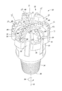
[0014] Figure 1 is a perspective view of an embodiment of a fixed cutter drill
bit made in
accordance with the principles described herein;
[0015] Figure 2 is a top view of the bit of Figure 1;
[0016] Figure 3 is a graphical illustration of an embodiment of a method for
forming one cutter
element of the bit of Figure 1 having a hard cutting table made from CVD
single crystal
diamond powder;
[0017] Figure 4 is a schematic pictorial illustration of the method of Figure
3;
[0018] Figures 5 is a graphical illustration of an embodiment of a method for
forming one
cutter element of the bit of Figure 1 having a hard cutting table made from a
plurality of stacked
CVD single crystal diamond layers; and
[0019] Figure 6 is a schematic pictorial illustration of the method of Figure
5.
DETAILED DESCRIPTION OF THE PREFERRED EMBODIMENTS
[0020] The following discussion is directed to various exemplary embodiments.
However, one
skilled in the art will understand that the examples disclosed herein have
broad application, and
that the discussion of any embodiment is meant only to be exemplary of that
embodiment, and
not intended to suggest that the scope of the disclosure, including the
claims, is limited to that
embodiment.
[0021] Certain terms are used throughout the following description and claims
to refer to
particular features or components. As one skilled in the art will appreciate,
different persons
may refer to the same feature or component by different names. This document
does not intend
to distinguish between components or features that differ in name but not
function. The
drawing figures are not necessarily to scale. Certain features and components
herein may be
shown exaggerated in scale or in somewhat schematic form and some details of
conventional
elements may not be shown in interest of clarity and conciseness.
[0022] In the following discussion and in the claims, the terms "including"
and "comprising"
are used in an open-ended fashion, and thus should be interpreted to mean
"including, but not
4
CA 02892056 2015-05-20
WO 2014/081654
PCT/US2013/070512
i01,-/i0u,
limited to... ." Also, the term "couple" or "couples" is intended to mean
either an indirect or
direct connection. Thus, if a first device couples to a second device, that
connection may be
through a direct connection, or through an indirect connection via other
devices, components,
and connections. In addition, as used herein, the terms "axial" and "axially"
generally mean
along or parallel to a central axis (e.g., central axis of a body or a port),
while the terms "radial"
and "radially" generally mean perpendicular to the central axis. For instance,
an axial distance
refers to a distance measured along or parallel to the central axis, and a
radial distance means a
distance measured perpendicular to the central axis.
[0023] Referring now to Figures 1 and 2, an embodiment of a drill bit 10 is
shown. In this
embodiment, bit 10 is a fixed cutter bit, also referred to as a drag bit, for
drilling through earthen
formations to form a borehole. Bit 10 has a central axis 11 and includes a bit
body 12, a shank
13, and a threaded connection or pin 14 for connecting bit 10 to a drill
string or bottom bole
assembly (BHA). Bit body 12 defines a bit face 20 that faces the formation
generally opposite
pin 16. A cutting structure 15 is disposed on the bit face for engaging and
cutting the formation
when weight-on-bit (WOB) is applied and bit 10 is rotated in a cutting
direction 18 about axis
11. In general, body 12 may be formed in a conventional manner using powdered
metal
tungsten carbide particles in a binder material to form a bard metal cast
matrix or machined from
a metal block, such as steel.
[0024] Referring still to Figures 1 and 2, cutting structure 15 includes a
plurality of angularly-
spaced primary blades 31 and a plurality of secondary blades 34 which extend
from bit face 20.
Primary blades 31 and secondary blades 34 are circumferentially arranged in an
alternating
fashion. Although bit 10 is shown as having three primary blades 31 and three
secondary blades
34, in general, bit 10 may comprise any suitable number of primary and
secondary blades.
[0025] Primary blades 31 and secondary blades 34 are integrally formed as part
of, and extend
from, bit body 12. In addition, primary blades 31 and secondary blades 34
extend generally
radially along bit face 20 and then axially along a portion of the periphery
of bit 10. In
particular, primary blades 31 extend radially from proximal central axis 11
toward the periphery
of bit 10, whereas secondary blades 34 are not positioned proximal bit axis
11, but rather, extend
radially along bit face 20 from a location that is distal bit axis 11 toward
the periphery of bit 10.
Primary blades 31 and secondary blades 34 are separated by drilling fluid flow
courses 19.
[0026] Referring still to Figures 1 and 2, each primary blade 31 includes a
cutter-supporting
surface 32 for mounting a plurality of cutter elements 40, and each secondary
blade 34 includes
a cutter-supporting surface 35 for mounting a plurality of cutter elements 40,
each having a
CA 02892056 2015-05-20
WO 2014/081654
PCT/US2013/070512
i01,-/i0u,
primary cutting face 44. In particular, cutter elements 40 are arranged
adjacent one another in a
radially extending row proximal the leading edge of each primary blade 31 and
each secondary
blade 34.
[0027] Each cutter element 40 is mounted such that its cutting face 44 is
generally forward-
facing. As used herein, "forward-facing" is used to describe the orientation
of a surface that is
substantially perpendicular to, or at an acute angle relative to, the cutting
direction of the bit
(e.g., cutting direction 18 of bit 10). For instance, a forward-facing cutting
face (e.g., cutting
face 44) may be oriented perpendicular to the cutting direction of bit 10, may
include a
backrake angle, and/or may include a siderake angle. However, the cutting
faces are preferably
oriented perpendicular to the direction of rotation of bit 10 plus or minus a
45 backrake angle
and plus or minus a 45 siderake angle. In addition, each cutting face 44
includes a cutting
edge adapted to positively engage, penetrate, and remove formation material
with a shearing
action, as opposed to the grinding action utilized by impregnated bits to
remove formation
material. Such cutting edge may be chamfered or beveled as desired. In this
embodiment,
cutting faces 44 are substantially planar, but may be convex or concave in
other embodiments.
[0028] In this embodiment, each cutter element 40 is the same. In particular,
each cutter
element 40 comprises an elongated and generally cylindrical support member or
substrate 41
and a disk-shaped, hard cutting layer or table 42 of superabrasive material
bonded to the
exposed end of support member 41. Each table 42 defines the cutting face 44 of
the
corresponding cutter element 40. In addition, each support member 41 is
received and secured
in a pocket formed in the cutter-supporting surface 32, 35 of the blade 31, 34
to which it is
mounted. In this embodiment, support members 41 are made of tungsten carbide
and tables 42
are made of a plurality of single synthetic diamond crystals formed by
chemical vapor
deposition (CVD), which may also be referred to herein as "CVD diamond(s)" or
"CVD single
crystal diamond(s)".
[0029] In this embodiment, each cutter element 40 has substantially the same
cylindrical
geometry and size. In particular, each primary cutting face 44 has
substantially the same
diameter. For an exemplary bit 10 having an overall gage diameter of 7.875 in.
(-- 20 cm), the
diameter of each cutting face 44 is about 0.625 in. 16 mm). In
other embodiments, the
geometry and/or size of one or more cutting face may be different.
[0030] Referring still to Figures 1 and 2, bit 10 also includes gage pads 51
of substantially equal
axial length measured generally parallel to bit axis 11. Gage pads 51 are
circumferentially-
spaced about the periphery of bit 10, one gage pad 51 intersecting and
extending from each
6
CA 02892056 2015-05-20
WO 2014/081654
PCT/US2013/070512
i01,-/i0u,
blade 31, 34. In this embodiment, gage pads 51 are integrally formed as part
of the bit body 12.
Gage pads 51 abut the sidewall of the borehole during drilling and help
maintain the size of the
borehole by a rubbing action when cutter elements 40 wear slightly under gage.
Gage pads 51
also help stabilize bit 10 against vibration. As one skilled in the art will
appreciate, numerous
variations in the size, orientation, and locations of the blades (e.g.,
primary blades 31,
secondary blades, 34, etc.), cutter elements (e.g., cutter elements 40), and
gage pads (e.g., pads
51) are possible.
[0031] Referring now to Figures 3 and 4, an embodiment of a method 300 for
forming one
cutter element 40 as previously described is shown. In this embodiment, table
42 of cutter
element 40 is made by sintering CVD single crystal diamond powder. Starting at
block 302, a
graphite powder 502 is converted into a single crystal diamond powder 504 by,
for example, a
high temperature, high pressure process such as hot-filament chemical vapor
deposition
(HFCVD). A single crystal diamond powder comprises a plurality of single
crystals, the size of
which may depend on the application. Although graphite powder 502 is used as
the starting
material in this embodiment, in other embodiments, a solid graphite block,
smaller graphite
cubes, irregularly shaped pieces of graphite, or other suitable form(s) of
graphite can be used as
the starter material. It should be appreciated that graphite powder 502 may
not completely
convert into single crystal diamond powder 504, and thus, after conversion,
the powder 504 is
preferably sorted to remove any remaining, unconverted graphite powder 502 (or
other starter
material).
[0032] At block 304, the single crystal diamond powder 504 is then grown via
chemical vapor
deposition (CVD) as a plurality of CVD single diamond crystals 508 on a
substrate 506.
Alternatively, in some embodiments, the graphite powder 502 can be directly
converted into a
plurality of CVD diamond crystals 508 without formation of the intermediate
single crystal
diamond powder 504. In either case, each CVD single diamond crystal of the
plurality of CVD
single diamond crystals 508 has the same shape. In an embodiment, each CVD
single diamond
crystal 508 has a rectangular prismatic shape (e.g., cubic) with six sides.
Each side has a length
and width between about 10 microns and about 20 microns.
[0033] In this embodiment, substrate 506 acts as the catalyst for the single
crystal growth at
block 304. In particular, substrate 506 is preferably made of cobalt (Co),
nickel (Ni), iron (Fe),
tungsten (W), molybdenum (Mo), or alloys thereof. Such metals operate, at
least initially, as
catalysts for CVD single diamond crystals 508 growth on the substrate 506.
Since the substrate
506 operates initially as a catalyst for single-crystal growth, embodiments
described herein
7
CA 02892056 2015-05-20
WO 2014/081654
PCT/US2013/070512
i01,-/i0u,
offer the potential to reduce or eliminate the need to add catalyst to powder
502 to initiate
crystal growth.
[0034] In this embodiment, substrate 506 is a non-planar three-dimensional
growth surface, for
example, a dowel, a pin, a convex or concave surface, or other feature shaped
as a semi-circle,
sphere, square, rectangle, trapezoid, cone, teardrop, or combinations thereof.
As will be
described in more detail below, in other embodiments, the single crystals
(e.g., CVD single
diamond crystals 508) are grown on a two-dimensional flat surface of a
substrate in at least one
layer.
[0035] After the plurality of CVD single diamond crystals 508 are grown on the
substrate 506
at block 304, at least a portion of the plurality of CVD single diamond
crystals 508 are removed
from substrate 506 at block 306. In this embodiment, the plurality of CVD
single diamond
crystals 508 are mechanically removed from the substrate 506 and converted
into a CVD
diamond crystal powder 510 at block 308. In general, the plurality of CVD
single diamond
crystals 508 can be mechanically removed and converted into powder 510 by
crushing,
scraping, grinding, or the like.
[0036] Referring still to Figure 3, at block 310, the CVD single crystal
diamond powder 510
formed at block 308 is disposed in a recess 514 of a mold 512, and a solid
tungsten carbide
support member 41 is placed in the mold on top of the powder 510. Support
member 41 and
the CVD single crystal diamond powder 510 in mold 512 are then subjected to
high pressure
and high temperature conditions at block 312 to form cutter element 40 at
block 314 by
simultaneously (a) sintering the CVD single crystal diamond powder 510 into a
monolithic or
unitary solid CVD single crystal diamond table 42 made entirely of CVD single
diamond
crystals, and (b) bonding the diamond table 42 to support member 41.
[0037] Cutter element 40 including the solid CVD single crystal diamond table
42 is removed
from mold 512 at block 316, and may undergo further treatment or processing at
block 318
before being mounted to a cutter-supporting surface 32, 35 at block 320 to
form bit 10. For
example, the mold 512 and/or support member 41 may act as a catalyst for the
formation of the
solid single crystal diamond table 42 - metal catalyst in the mold 512 and/or
support member
41 may infiltrate CVD diamond table 42 during formation of cutter element 40
in block 314.
Accordingly, leaching is preferably performed in block 318 to remove at least
some of the
catalysts that infiltrate table 42 during formation of cutter element 40 at
block 314. As another
example, the diamond table 42 may be further processed in block 318 to conform
table 42 to
specific dimensions.
8
CA 02892056 2015-05-20
WO 2014/081654
PCT/US2013/070512
i01,-/i0u,
[0038] Referring now to Figures 5 and 6, an embodiment of a method 400 for
forming one
cutter element 40 as previously described is shown. In this embodiment, table
42 of cutter
element 40 is made by sintering stacked layers of CVD single crystal diamonds.
Similar to
method 300 previously described, method 400 begins at blocks 302, 304, where
graphite
powder 502 is converted into single crystal diamond powder 504 by, for
example, HFCVD,
and then, the single crystal diamond powder 504 is then grown via chemical
vapor deposition
(CVD) as plurality of CVD single diamond crystals 508 on a substrate 506. As
previously
described, each CVD single diamond crystal of the plurality of CVD single
diamond crystal
508 has a uniform shape. More specifically, each CVD single diamond crystal
508 has a
rectangular prismatic shape (e.g., cubic) with six sides. Each side has a
length and width
between 10 microns and 20 microns. However, in this embodiment, the plurality
of CVD
single diamond crystals 508 are grown in at least one layer on planar or flat
surface of substrate
506. In general, substrate 506 can be two-dimensional or three dimensional,
and the plurality
of CVD single diamond crystals may be grown on any or all surfaces as
appropriate given the
respective surface area of each surface. Substrate 506 operates, at least
initially, as catalysts for
CVD single diamond crystal growth on the substrate 506. Accordingly, as
previously
described, substrate 506 is preferably made of cobalt (Co), nickel (Ni), iron
(Fe), tungsten (W),
molybdenum (Mo), or alloys thereof. The growth directly on the substrate 506
is initiated by
the substrate 506 itself since it acts as a catalyst, and subsequent layers of
crystals may grow on
the initially layer formed on the substrate 506.
[0039] At block 304, after the layer(s) of CVD single diamond crystals 508 are
grown on the
substrate 506, at least a portion of the plurality of CVD single diamond
crystals 508 are
removed from the substrate 506 at block 406. In this embodiment, the removal
process does
not damage or crush the plurality of CVD single diamond crystals 508 as in
block 306 of
method 300 previously described. Rather, in this embodiment, at block 406, a
plurality of in-
tact sheets 602 of the CVD single diamond crystals 508 are stamped, cut or
otherwise removed
from the substrate with minimal damage to the edges of the removed portion
during the
removal process at block 406. Each sheet of the plurality of in-tact sheets
602 can comprise
one or more layers of the CVD single diamond crystals 508.
[0040] Referring still to Figures 5 and 6, the plurality of sheets 602 removed
at block 406 are
disposed in recess 514 of the mold 512 at block 410, and support member 41 is
placed in recess
514 on top of the stack of sheets 602. Within recess 514, the plurality of
sheets 602 are
preferably arranged in a vertical stack one on-top of the other, however, in
general, the sheets
9
CA 02892056 2015-05-20
WO 2014/081654
PCT/US2013/070512
i01,-/i0u,
(e.g., sheets 602) can be arranged in other orientations (e.g., arranged in a
horizontal row one
next to the other, or at any other angle as appropriate to the subsequent
processing and/or end
application). The support member 41 and the CVD single crystal diamond sheets
602 in mold
512 are then subjected to high pressure and high temperature conditions in
block 412 to form
cutter element 40 at block 414 by simultaneously (a) sintering sheets 602 into
a monolithic or
unitary solid CVD single crystal diamond table 42 made entirely of CVD single
diamond
crystals, and (b) bonding the diamond table 42 to support member 41. The
cutter element 40
including the solid CVD single crystal diamond table 42 is removed from mold
512 at block
416, and may undergo further treatment or processing (e.g., leaching) in block
418 before being
mounted to a cutter-supporting surface 32, 35 at block 420 to form bit 10. In
particular, a
catalyst such as cobalt (Co), iron (Fe), nickel (Ni), or combinations thereof,
in the support
member 41 may infiltrate the CVD diamond table 42 during formation of cutter
element 40 in
block 414, and thus, leaching is preferably performed in block 418 to remove
the catalyst from
table 42.
[0041] In the conventional method for making cutter element described above,
the [111] plane
of the irregularly-shaped particles in the polycrystalline diamond powder may
be the cleavage
plane and therefore the weakest plane. However, using embodiments of methods
300, 400
disclosed herein, the growth planes of the plurality of CVD single diamond
crystals 508 can be
controlled so that the crystals are grown on the substrate 506 along a
specific plane. In a
preferred embodiment, the plurality of CVD single diamond crystals 508 with a
[100]
orientation are grown on the substrate 506. It should be appreciated that the
growth of [100]
single crystals may be tightly controlled to ensure that the growth does not
transition to a
polycrystalline structure. This directional crystal growth may lead to
increased strength under
high temperatures and pressures and, as such, result in decreased failure of
components under
high temperature and/or high pressure.
[0042] In the conventional method of forming diamond powder for use in making
the PD table,
a catalyst such as cobalt (Co) or nickel (Ni) is typically added to the
starter graphite powder to
help facilitate the growth of diamond crystals. However, such catalysts
operate as undesirable
impurities or contaminants in the PD tables. In particular, the catalyst and
diamond crystals
have different coefficients of thermal expansion, and thus, when the PD table
is subjected to
high temperature conditions, differences in the expansion of the catalysts and
diamond may
lead to cracks within the table. Consequently, the diamond powder is leached
to remove the
catalyst. However, in the methods disclosed herein (e.g., methods, 300, 400),
catalysts are not
CA 02892056 2015-05-20
WO 2014/081654
PCT/US2013/070512
i01,-/i0u,
added to the starting graphite powder (e.g., powder 502). Rather, initially,
the substrate (e.g.,
substrate 506) functions as a catalyst to initiate diamond growth, and once
initiated, the
diamond growth continues on its own. Consequently, it may not be necessary to
leach CVD
diamond powder 510. It should be appreciated that catalyst in the support
member 41 may
infiltrate the CVD diamond table 42 during formation of cutter element 40 in
mold 512, and
thus, leaching is preferably performed in blocks 318, 418 to remove the
catalyst from table 42.
[0043] In the manner described, cutter elements 40 with tungsten carbide
support members
41 and CVD diamond table 42 can be formed, and then mounted to surfaces 32, 35
to form
bit 10. In methods 300, 400, powder 510 or sheets 602 are placed in mold 512
along with a
tungsten carbide support member 41 to form cutter element 40. However, other
CVD single
diamond crystal components of any desired shape can be formed in a mold (e.g.,
mold 512)
in a similar manner. If such other CVD single diamond crystal components are
to be bonded
to a second component (e.g., a tungsten carbide substrate), that second
component can be
placed in the mold with the CVD single diamond material (e.g., powder 510 or
sheets 602).
Alternatively, the other the CVD single diamond material component can be
formed on its
own in the mold, and then secured to a second component or device.
[0044] While preferred embodiments have been shown and described,
modifications thereof
can be made by one skilled in the art without departing from the scope or
teachings herein.
The embodiments described herein are exemplary only and are not limiting. Many
variations
and modifications of the systems, apparatus, and processes described herein
are possible and
are within the scope of the invention. For example, the relative dimensions of
various parts,
the materials from which the various parts are made, and other parameters can
be varied.
Accordingly, the scope of protection is not limited to the embodiments
described herein, but
is only limited by the claims that follow, the scope of which shall include
all equivalents of
the subject matter of the claims. Unless expressly stated otherwise, the steps
in a method
claim may be performed in any order. The recitation of identifiers such as
(a), (b), (c) or (1),
(2), (3) before steps in a method claim are not intended to and do not specify
a particular
order to the steps, but rather are used to simplify subsequent reference to
such steps.
11