Note: Descriptions are shown in the official language in which they were submitted.
CA 02892198 2015-05-22
ZEROING ADJUSTMENT FOR DEPTH CONTROL SYSTEM
BACKGROUND OF THE INVENTION
I. Field of the Invention
[0001] The present invention generally relates to agricultural seed
planting implements and
to the depth-setting mechanism on furrow opening assemblies of such
implements, and more
particularly to an assembly for adjusting the depth-setting mechanism.
2. Description of the Related Art
[0002] Farmers utilize a wide variety of seed planting implements,
including seed drills and
planters. In a known type of planting implement, seed planting or row units
are attached to a
toolbar extending transverse to the direction of planting. The toolbar is
coupled to a tractor or
other work vehicle suitable for pulling the planting implement along a field
that is to be seeded
to a crop. Each planting unit includes a ground penetrating assembly, often
including one or
more discs, for opening a seed trench or furrow in the ground as the planting
implement is
pulled across a field. Components of the ground penetrating assembly shape the
bottom and
sides of the seed trench, and a seed metering device provides individual seeds
at a controlled
rate for deposit in the seed trench. Furrow closing components of each row
unit close the seed
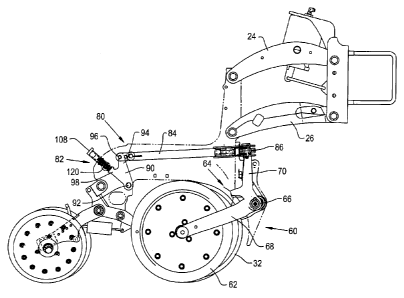
trench in a controlled manner.
[0003] It is a desirable and perhaps even primary agronomic principle that
seeds should be
planted at precisely controlled and consistent depths both within a row and
from row to row.
Since a single planting implement may be used to plant several different types
of crops and/or
the same crop in different planting locations under different planting and
growing conditions, it
is necessary that the planting depth is adjustable so that the seeds are
placed at a depth that has
been determined to be the best for seed germination and plant growth of the
particular crop
1
51267
CA 02892198 2015-05-22
under the existing and anticipated conditions.
[0004] To control planting depth, it is known to provide gauge wheels that
travel on the
surface of the field to control the depth to which the ground penetrating
assembly can run, the
positions of the gauge wheels being adjustable so that the depth of the seed
trench can be
controlled within fractions of an inch. Adjustment linkages are provided for
changing the
relative positioning of the gauge wheels with respect to the ground
penetrating assembly. It is
known to move the adjustment linkage by a handle connected thereto, the handle
engaging a
register having multiple positions for securing the handle to maintain the
position to which the
handle is adjusted.
[0005] As growers have gained greater understanding about seed germination
and plant
growth, and as soil preparation procedures have changed and improved, crop
growers have
demanded more precise control over seed placement both in the spacing between
seeds and in
the depth at which the seeds are placed below the soil surface. Accordingly,
there is both a
demand and a need for even more precise control over the depth of the seed
trench that is
formed during planting operations. While depth-setting mechanisms have been
designed for
ever more precise settings, the linkages and other structures forming the
depth setting
mechanisms have multiple components and connections which can lead to setting
errors due to
the variable effects of tolerance stack-up, wear and the like. In planting
implements having
multiple seed planting or row units, it is necessary that all units be
similarly calibrated so that all
units plant to the same planting depths when set to the same settings. The
multiple components
and linkages present in depth-setting mechanisms can acquire unacceptably
large variations
from one row unit to another in the accumulated stack of tolerances in the
component parts even
when new, and after wear has occurred and/or if parts have been replaced,
planting depths can
vary significantly between row units that have been adjusted to the same
planting depth settings.
2
51267
CA 02892198 2015-05-22
[0006] What is needed in the art is a structure for zeroing the depth
setting mechanisms in a
seed planting implement to adjust out the varying effects of tolerance stack-
up and wear
between different seed planting units of the implement.
SUMMARY OF THE INVENTION
[0007] The present invention provides a seed planting implement with
consistent depth
setting control for ground penetrating components of the implement by
providing an adjustable
link in the adjustment mechanism to compensate for the variable effects of
tolerance stack-up
and wear.
[0008] In one form thereof, the invention is directed to an agricultural
seed planting
implement with a ground penetrating assembly, a depth setting linkage assembly
including a
control assembly and a depth control linkage arm associated with the ground
penetrating
assembly and having adjustable positions for changing a depth to which the
ground penetrating
assembly can operate. The depth control linkage arm is selectively variable in
length.
[0009] In another form, the invention is an agricultural seed planting
implement with a
toolbar and a plurality of individual seed planting units connected to the
toolbar. Each seed
planting unit of the plurality of seed planting units includes a ground
penetrating assembly and a
depth control assembly for changing a depth to which the ground penetrating
assembly can
operate. Each depth control assembly is adjustable to a common setting from
which depth
settings are made for the ground penetrating assemblies.
[0010] In a further form thereof, the invention is an agricultural seed
planting implement
with a ground penetrating assembly, an adjustable gauge wheel supporting said
ground
penetrating assembly at controlled penetration depths; and a depth control
linkage arm
adjustably positioning said gauge wheel, said depth control linkage arm having
a selectively
3
51267
CA 02892198 2015-05-22
, .
variable length.
[0011] An advantage of the zeroing adjustment for depth control
systems disclosed herein is
that the penetration depth for seed planting equipment can be more accurately
and consistently
set across multiple planting units of an agricultural seed planting implement.
[0012] Another advantage of the zeroing adjustment for depth
control systems disclosed
herein is that it compensates for the variable effects of tolerance stack-up
and wear.
BRIEF DESCRIPTION OF THE DRAWINGS
[0013] The above-mentioned and other features and advantages of
this invention, and the
manner of attaining them, will become more apparent and the invention will be
better
understood by reference to the following description of an embodiment of the
invention taken in
conjunction with the accompanying drawings, wherein:
[0014] Fig. 1 is a perspective view of an agricultural seed
planting implement;
[0015] Fig. 2 is a perspective view of one of the seed planting
units of the seed planting
implement;
[0016] Fig. 3 is a side view of the seed planting unit;
[0017] Fig. 4 is another perspective view of the seed planting
unit, showing the unit from an
angle different from the angle shown in the perspective view of Fig. 2;
[0018] Fig. 5 is a fragmentary side view of the seed planting
unit illustrating inner
components used for depth setting;
[0019] Fig. 6 is a perspective view a depth setting linkage
assembly in the seed planting
unit;
[0020] Fig. 7 is a side view of the depth linkage assembly;
[0021] Fig. 8 is a fragmentary elevation view of the seed
planting unit;
4
51267
CA 02892198 2015-05-22
[0022] Fig. 9 is a cross-sectional view of the seed planting unit; and
[0023] Fig. 10 is another perspective view of the linkage assembly as
installed and adjusted.
[0024] Corresponding reference characters indicate corresponding parts
throughout the
several views. The exemplification set out herein illustrates one embodiment
of the invention
and such exemplification is not to be construed as limiting the scope of the
invention in any
manner.
DETAILED DESCRIPTION OF THE INVENTION
[0025] Referring now to the drawings more specifically and to Fig. 1 in
particular, a seed
planting implement 10 is shown. Seed planting implement 10 has a frame that
includes a tow
bar assembly 12 having a tow bar 14 and a connection assembly 16 at the
longitudinally
forward end thereof configured for mating with a corresponding hitch of a
tractor or other work
vehicle (not shown) for pulling seed planting implement 10 through a field. A
laterally
extending toolbar 18 is generally transverse to tow bar 14 and thereby
generally transverse to
the direction implement 10 is towed during planting operations. A plurality of
seed planting
units (or row units) 20 are connected to toolbar 18 in a side by side
relationship, each of the
seed planting units (row units) being substantially identical to the others.
In the exemplary
embodiment shown, seed planting implement 10 includes sixteen seed planting
units 20, only
some of which are identified with reference numbers; however, it should be
understood that
more or fewer seed planting units can be provided on a particular seed
planting implement.
[0026] Referring now primarily to Fig. 2 through Fig. 5, each seed planting
unit 20 includes
a frame 22 that is connected to toolbar 18 by upper arms 24 and lower arms 26,
each arm 24, 26
being connected to frame 22 and to toolbar 18. Accordingly, each seed planting
unit 20 extends
rearward from toolbar 18 to plant a row of seeds as seed planting implement 10
is towed across
51267
CA 02892198 2015-05-22
a field. The individual planting units 20 are spaced along toolbar 18 to
provide planted seed
rows of a desired spacing. During a planting operation, forward movement of
seed planting
implement 10 causes each seed planting unit 20 to form a seed trench, deposit
equally spaced
seeds in the seed trench and close the seed trench over the seeds deposited in
the seed trench.
[0027] Each seed planting unit 20 includes a ground penetrating or seed
trench opening
assembly 30 (Fig. 3) having a pair of forwardly and downwardly angled opening
discs 32 that
converge forwardly and downwardly to open a furrow or seed trench as seed
planting
implement 10 moves forward. A seed metering system 34 receives seeds from a
seed hopper 36
and provides individual seeds at a controlled rate to a seed tube 38 for
deposit in the bottom of
the seed trench formed. A vacuum system 40 (Fig. 1), which includes a fan 42
and air lines 44,
provides vacuum to seed metering system 34 for the operation of the seed
metering system in
supplying seeds to seed tube 38.
[0028] A seed trench closing mechanism 50 (Fig. 1) at the trailing end of
each seed planting
unit 20 closes the seed trench after the seeds have been deposited in the seed
trench. Seed
trench closing mechanism 50 includes a pair of closing wheels 52 (Fig. 2) that
operate on
opposite sides of the seed trench to move soil back into the seed trench and
over the seeds
deposited in the bottom of the seed trench. A trailing press wheel 54 (Fig. 1)
travels along the
top of the seed trench and firms the soil replaced in the seed trench to
eliminate air pockets.
[0029] The depth to which opening discs 32 are allowed to penetrate the
ground is
controlled by a depth control assembly 60 (Fig. 5) that includes a pair of
gauge wheels 62,
gauge wheel arms 64 and a depth setting and linkage assembly 80. One of the
gauge wheels 62
is provided adjacent each opening disc 32. Each gauge wheel 62 is rotatably
mounted on one of
the gauge wheel arms 64 that are pivotally connected at a pivotal attachment
66 to seed planting
unit frame 22. Each gauge wheel arm 64 has a wheel retention segment 68
extending generally
6
51267
CA 02892198 2015-05-22
rearward from pivotal attachment 66 and a control segment 70 extending
generally upward from
pivotal attachment 66. Pivotal movement of gauge wheel arm 64 about pivotal
attachment 66 to
frame 22 changes the relative height position of gauge wheel 62.
[0030] A pivoted position to which each gauge wheel arm 64 is placed is
controlled by
depth setting and linkage assembly 80 having a depth setting control assembly
82, a depth
control linkage arm 84 and a wobble bracket 86 connected to linkage arm 84 by
a pivotal
connection 88. Control assembly 82 adjusts an axial position for linkage arm
84 and thereby
the position of wobble bracket 86, with wobble bracket 86 engaging control
segments 70 of
gauge wheel arms 64. Raising gauge wheels 62 allows opening discs 32 to
penetrate deeper
into the ground, and lowering gauge wheels 62 limits the depth to which discs
32 can penetrate
into the ground.
[0031] Referring now primarily to Fig. 4 through Fig. 6, control assembly
82 includes a
pivot arm 90 of general V-shape, with a pivotal connection 92 at the base
thereof to seed
planting unit frame 22. An inner arm 94 of pivot arm 90 has a pivotal
connection 96 to depth
control linkage arm 84. An outer arm 98 of pivot arm 90 extends through a
depth setting
register 100. Depth setting register 100 defines a slot 102 with a first row
of notches 104 along
one side of slot 102 and a second row of notches 106 along an opposite side of
slot 102.
Opposed pairs of notches including one of the notches 104 and one of the
notches 106 define
securing locations for securing the position of pivot arm 90 after adjustment
thereof.
[0032] A handle 108 is provided on the distal end of outer arm 98 and
includes laterally
projecting position holding pegs 110, 112 for engaging notches 104, 106 of
register 100. The
pairs of notches including one of the notches 104 and one of the notches 106
secure the position
of pivot arm 90 by receiving and engaging pegs 110, 112. Handle 108 is mounted
on a spring
114, and can be depressed relative to outer arm 98 such that pegs 110, 112
disengage notches
7
51267
CA 02892198 2015-05-22
104, 106 by sliding inwardly through the notches so that handle 108 can be
moved fore and aft
in slot 102 to align pegs 110, 112 with different pairs of notches 104, 106.
As handle 108
rebounds outwardly, pegs 110, 112 slide into the pair of notches 104, 106 with
which the pegs
are aligned. Movement of handle 108 fore and aft pivots pivot arm 90 about its
pivotal
connection 92, and thereby extends or withdraws depth control linkage arm 84,
to alter the
position of wobble bracket 86, which in turn controls the positions of control
segments 70 and
thereby the allowable height of gauge wheels 62.
[0033] Depth control linkage arm 84 includes a rearward portion 130 that is
connected to
pivot arm 90 by pivotal connection 96, and a forward portion 132 that is
connected to wobble
bracket 86 by pivotal connection 88. An intra-link connection 134 between
rearward portion
130 and forward portion 132 is axially adjustably so that the overall length
of linkage arm 84 is
selectively variable. Rearward portion 130 and forward portion 132 are
telescopically engaged
with one another to accommodate the overall axial adjustability of connection
134 to change the
overall length of linkage arm 84.
[0034] Referring now more particularly to Fig. 7, connection 134 includes a
bolt 136
extending through one or more fixed block 138, 140 fixed between side plates
142, 144 of
forward portion 132 and received by threaded engagement in a threaded block
146 affixed to
rearward portion 130. Bolt 136 includes a shank 150 that is threaded along at
least a portion of
an end thereof, and a head 152 having a drive configuration 154 (Figs. 9 & 10)
formed therein
for engagement by an appropriate tool for rotating bolt 136. In the exemplary
embodiment
shown, drive configuration 154 is a hexagonal depression for receiving a hex
key (Allen
wrench) in rotational drive engagement. It should be understood that drive
configuration 154
can be of other shaped depressions in head 152 to engage other internally
received drive tools,
or drive configuration 154 can be an external shape of head 152 to receive a
wrench, drive
8
51267
CA 02892198 2015-05-22
socket or the like. Head 152 includes opposed external flats 156, 158 (Fig.
10) that also can
receive a wrench, drive socket or the like. Advancing the threaded engagement
of bolt 136 into
threaded block 146 decreases the overall length of depth control linkage arm
84, and retracting
the threaded engagement of bolt 136 from threaded block 146 increases the
overall length of
depth control linkage arm 84.
[0035] Referring now particularly to Fig. 10, a lock mechanism in the form
of a bracket or
cage 160 is provided to secure the position to which bolt 138 has been
adjusted. Cage 160 has
sides 162, 164 and an end 166. End 166 has a shaped hole 168 therein including
opposed flats
170, 172 to receive and engage head 152, with flats 156, 158 of head 152
received against flats
170, 172 of shaped hole 168 to prevent further rotation of bolt 138. Sides
162, 164 of cage 160
are received against side plates 142, 144, and together side plates 142, 144
and sides 162, 164
form aligned holes 174, 176 for receiving a pin forming pivotal connection 88.
It should be
understood that other structures can be used for preventing the unintended
rotation of bolt 136
after the adjustment thereof.
[0036] Zero adjustment or calibration of depth control assembly 60 is
performed upon
initial assembly and can be performed again from time to time as a maintenance
procedure. For
example, it may be desirable to zero adjust the system after significant wear
and/or when
replacement parts have been installed. Zero adjustment is performed with
wobble bracket 86,
pivotal connection 88 and cage 160 not yet installed (during initial assembly)
or removed (when
performed as a maintenance step). Seed planting implement 10 is adjusted so
that toolbar 18 is
elevated, lifting all seed planting units 20 off the ground. As illustrated in
Fig. 8, each gauge
wheel 62 drops, pivoting its respective gauge wheel arm 64 about the pivotal
attachment 66
thereof until adjustable control segment 70 contacts a frame stop 178. This
allows removal of
wobble bracket 86, pivotal connection 88 and cage 160 when performed as a
maintenance
9
51267
CA 02892198 2015-05-22
operation or the insertion of depth control linkage arm 84 during assembly.
10037] With seed planting implement 10 thus prepared, toolbar 18 is lowered
until opening
discs 32 barely contact a flat level surface upon which implement 10 is
positioned. Opening
discs 32 thereby rest at a zero penetration setting, and depth control
assembly 60 can be
adjusted for proper registration of handle 108 at the zero penetration
setting. Control assembly
82 is adjusted such that handle 108 is engaged with the appropriate notches
104, 106 for a zero
penetration setting. Bolt 136 is then adjusted relative to threaded block 146
to advance further
into or to withdraw further from threaded block 146, while at all times
remaining threadedly
engaged there with. In this way, the overall length of depth control linkage
arm 84 is adjusted
so that when wobble bracket 86 is re-attached thereto it will properly engage
control segments
70 of gauge wheel arms 64 and without unacceptable looseness. It should be
understood that
the appropriate length for control linkage arm 84 can be determined in
numerous ways,
including measurement between the end thereof and a fixed point such as, for
example, depth
setting register 100 or another fixed point of reference. A convenient way for
determining the
proper overall length of linkage arm 84 is by the use of a gauge 180. As
illustrated in Fig. 9,
gauge 180 includes wings 182, 184 to be received in wobble bracket slots 186
of control
segments 70. Bolt 136 is rotated so as to advance further into, or withdraw
further from
threaded block 146 and thereby change the overall length of depth control
linkage arm 84 until
the outer end of control linkage arm 84 is received at a designated position
relative to gauge 180
and wings 182, 184 are properly received in wobble bracket slots 186. Bolt
head 152 is
adjusted as necessary so that flats 156, 158 thereof are properly positioned
such that cage 160
can be installed with shaped hole 168 thereof engaging bolt head 152, with
flats 156, 158 of bolt
head 152 disposed against flats 170, 172 in shaped hole 168 of cage 160. Gauge
180 is
removed, and cage 160 is installed. Wobble bracket 86 and pivotal connection
88 are installed,
51267
CA 02892198 2015-05-22
,
thereby securing cage 160 in position and locking bolt 136 against unintended
rotation.
[0038] When all row units 20 of seed planting implement 10 are
adjusted in this manner to a
common zero penetration setting, each will have a common elevation relative to
the zero setting
to which it was adjusted. Each can then be set so that the opening discs 32
thereof will
penetrate a same depth into the ground if the control assemblies 82 thereof
are adjusted to
similar settings in registers 100. In that way, all row units that are set to
the same settings will
deposit seeds at the same depths below the surface of the ground.
[0039] While this invention has been described with respect to at
least one embodiment, the
present invention can be further modified within the spirit and scope of this
disclosure. This
application is therefore intended to cover any variations, uses, or
adaptations of the invention
using its general principles. Further, this application is intended to cover
such departures from
the present disclosure as come within known or customary practice in the art
to which this
invention pertains and which fall within the limits of the appended claims.
11
51267