Note: Descriptions are shown in the official language in which they were submitted.
CA 02892434 2015-05-22
A PICKUP AND ALIGNMENT MECHANISM FOR LOGS
AND A METHOD OF USE
FIELD OF THE INVENTION
This invention relates to a pickup and alignment mechanism for logs and a
method of using said mechanism.
BACKGROUND OF THE INVENTION
In many states trees are harvested for firewood. The trees are cut in the
forest
by loggers. The branches are removed from the down tree and then the trunk of
the tree
is cut into approximately 100 inch lengths (8.3 feet). The approximately 100
inch long
logs are stacked on a logging truck and transported to customers who order
firewood.
Farmers, cottage owners, small businesses, etc. buy a truck load, about 200 or
more
such logs, at a time. These logs are stacked on the ground, essentially
parallel to one
another, forming an approximately triangular shaped pile. The customer is
responsible
for cutting each log into smaller pieces of firewood, having lengths of from
16 inches to
about 25 inches or longer, that can be burned in a wood burning furnace,
stove,
fireplace, camp fire, etc. If the diameter of each log is large, each piece of
firewood can
be split using a hydraulic wood splitter, an axe or some other device.
However, most
wood burning furnaces today are designed to receive a cylindrically shaped log
having a
diameter of up to about 25 inches without the need to first split the log.
For those people who burn a large quantity of wood in a season, it takes time
to
cut each log and stack the pieces of wood in a desired location. Normally, the
log
cutting is accomplished by a sole person who does not have a helper. The log
cutting is
physical work requiring cutting, lifting and stacking of the cut pieces of
wood. In a typical
setup, the outermost log, located at the bottom and side of the stack of logs
is generally
cut first. This means that as the log is cut with a chain saw, the blade of
the chain saw
may contact the dirt or ground as the three, four or five cuts are made to
each
approximately 100 inch log. Four or more pieces of firewood can be obtained
from each
100 inch long log. The contact of the blade of the chain saw with the ground
will
- 1 -
eventually cause the blade to become dull. A dull blade has to be resharpened,
a time
consuming process. In addition, if the blade of the chain saw hits a rock, the
blade can
be damaged. Furthermore, the chain saw operator is required to bend over so as
to cut
each log in three or more places at ground level in order to obtain the
required lengths.
This need to bend over can cause back pain after an extended period of time.
Lastly, the
cut firewood has to be manually lifted and stacked in a desired location. This
is hard
physical labor that can tax an older person or a person suffering from some
kind of health
problem.
Another option is for two people to lift each log above ground level and place
it on
two or more supports. The 100 inch long log can then be cut into four or more
separate
pieces of firewood without worrying about the blade of the chain saw
contacting the
ground. However, two people are not always available.
Now, a pickup and alignment mechanism for logs has been invented along with a
method of using the mechanism. This pickup and alignment mechanism automates
the
cutting, lifting and transporting process and reduces the physical exertion
mentioned
above. This pickup and alignment mechanism can be used by a person who
actually
burns the firewood or by a handy man that has been hired to cut the entire
stack of logs.
SUMMARY OF THE INVENTION
Briefly, this invention relates to a pickup and alignment mechanism for logs
and a
method of use. The pickup and alignment mechanism can be physically attached
and
connected, hydraulically or pneumatically, to a motorized vehicle. The pickup
and
alignment mechanism includes a frame having a first rail, a second rail and a
face plate.
The first rail is spaced apart from the second rail. The first and second
rails each have a
first end and a second end. The face plate connects the first and second rails
together.
The face plate has an upper edge positioned adjacent to the first rail and a
lower edge
positioned adjacent to the second rail. A connector on the motorized vehicle
is secured
to the face plate and allows the pickup and attachment mechanism to be
physically
attached to the motorized vehicle. The face plate includes a first abutment
point located
adjacent to the upper edge of the face plate, and second and third spaced
apart
attachment points located adjacent to the lower edge of the face plate. The
first point is
also located approximately midway between the second and third attachment
points.
- 2 -
CA 2892434 2020-02-26
The pickup and alignment mechanism also includes a plurality of L-shaped
tines.
Each of the plurality of L-shaped tines is an integral member having a
horizontal portion
aligned approximately perpendicular to a vertical portion. Each of the
vertical portions is
secured to at least one, if not both, of the first and second rails. The
pickup and
alignment mechanism further includes a pair of side tines connected to a
cylinder which
can be actuated to simultaneously or sequentially move the pair of side tines
towards or
away from one another. One of the pair of side tines is positioned adjacent to
the first
end of the second rail and the other pair of side tines is positioned adjacent
to the
second end of the second rail. A hydraulic or pneumatic hose is connected
between the
motorized vehicle and the cylinder for supplying pressurized fluid or air to
actuate the
cylinder. Lastly, the pickup and alignment mechanism includes a plurality of
bumpers,
each positioned between one of the pairs of L-shaped tines. Each of the
bumpers is
secured to the vertical portions of each of the pairs of the L-shaped tines.
Each of the
bumpers is spaced apart from an adjacent bumper. The bumpers provide clearance
such that a person with a saw can cut the logs positioned on the plurality of
L-shaped
tines without worrying about contacting the first and second rails or the face
plate with
the blade of the saw and damaging it.
The plurality of L-shaped tines can be maneuvered to pickup from between one
to six logs at a time and raise the logs a desired distance off the ground.
The one to six
logs are aligned in a single row on the L-shaped tines. The pair of side tines
functions to
longitudinally align the logs relative to one another so that they can be cut
to a desired
length by a person with a saw.
An alternative pickup and alignment mechanism is also taught which utilizes a
plurality of chain saws which are pivotably mounted to the frame. The chain
saws can
be sequentially activated so as to make cuts through all of the logs
positioned on the
plurality of L-shaped tines. The logs can be arranged in a three-sided
configuration on
the L-shaped tines. Both of these pickup and alignment mechanisms are easy to
operate, save time and provide an efficient way of cutting firewood.
The general object of this invention is to provide a pickup and alignment
mechanism for logs. A more specific object of this invention is to provide a
pickup and
alignment mechanism that can be removably mounted to the front end of a
tractor, a
utility tractor, a BobcatTM, a skid steer loader or some other kind of
motorized vehicle,
and pick up and align from one to six logs so that they can be easily cut by a
person with a
- 3 -
CA 2892434 2020-07-09
chain saw, above ground level, before being transported to a designated
storage location.
Another object of this invention is to provide a pickup and alignment
mechanism
which can easily and quickly be mounted to a motorized vehicle.
Still another object of this invention is to provide a pickup and alignment
mechanism which can be utilized by a sole person.
A further object of this invention is to provide a method of picking up and
aligning
from one to six, approximately 100 inch long, logs and then raising the logs
above ground
level so that they can be easily cut.
Still further, an object of this invention is to provide a method of
transporting
multiple pieces of cut firewood to a storage location using the pickup and
alignment
mechanism.
In one embodiment of the present invention there is provided a pickup and
alignment mechanism for logs comprising: a) a frame including a first rail, a
second rail
and a face plate, the first rail being spaced apart from the second rail, the
first and second
rails each having a first end and a second end, the face plate connecting the
first rail to
the second rail, and the face plate having an upper edge positioned adjacent
to the first
rail and a lower edge positioned adjacent to the second rail; b) a connector
secured to the
face plate which allows the pickup and attachment mechanism to be attached to
a
motorized vehicle, the connector including a first abutment point located
adjacent to the
upper edge of the face plate, second and third spaced apart attachment points
located
adjacent to the lower edge of the face plate, and the first abutment point
being located
approximately midway between the second and third attachment points; c) five
pairs of
tines, each of the five pairs of tines comprising two individual tines, each
of the individual
tines being an integral member having an L-shaped configuration which includes
a
horizontal portion aligned approximately perpendicular to the frame and a
vertical portion
secured to the first and second rails, the two individual tines in each of the
pairs of tines
are separated by a distance d, and each of the five pairs of tines is
separated from an
adjacent pair of tines by a distance di, and d is greater than di; d) a pair
of side tines, each
of the pair of side tines connected to one of a pair of cylinders which can be
actuated to
move each of the pair of side tines separately towards and away from one
another, one
of the pair of side tines being positioned adjacent to the first end of the
second rail and the
other of the pair of side tines being positioned adjacent to the second end of
the second
rail; e) a hose for supplying pressurized fluid or air between the motorized
vehicle and
- 4 -
CA 2892434 2020-02-26
, v
each of the pair of cylinders, and the pressurized fluid or air actuates the
pair of cylinders;
and f) a plurality of bumpers each formed from a hard material, each of the
bumpers
positioned between two individual tines which makeup each of the five pairs of
tines, each
of the bumpers movably secured to the frame by a mechanical fastener, each of
the
bumpers being spaced apart from an adjacent bumper, each of the bumpers
providing
clearance such that the logs positioned on the five pairs of tines can be cut
with a chain
saw without the chain saw contacting the frame, and the five pairs of tines
can be
maneuvered to pickup from between one to six logs at a time and raise the logs
a desired
distance above the ground, and the pair of side tines can longitudinally align
the logs
relative to one another so that they can be cut to a desired length.
In another embodiment of the present invention there is provided a pickup and
alignment mechanism for logs which is capable of being attached to a motorized
vehicle,
comprising: a) a frame including a first rail, a second rail and a face plate,
the first rail
being spaced apart from the second rail, the first and second rails each
having a first end
and a second end, the face plate connecting the first rail to the second rail,
and the face
plate having an upper edge positioned adjacent to the first rail and a lower
edge positioned
adjacent to the second rail; b) a connector secured to the face plate which
allows the
pickup and attachment mechanism to be attached to the motorized vehicle, the
connector
including a first abutment point located adjacent to the upper edge of the
face plate,
second and third spaced apart attachment points located adjacent to the lower
edge of
the face plate, and the first abutment point being located approximately
midway between
the second and third attachment points; c) a first pair, a second pair, a
third pair and a
fourth pair of tines, each of the first, second, third and fourth pairs of
tines comprising two
individual tines, each of the individual tines being an integral member having
an L-shaped
configuration which includes a horizontal portion aligned approximately
perpendicular to
a vertical portion, the horizontal portion having a length and the vertical
portion having a
height, each vertical portion being movably secured to both the first and
second rails such
that each of the individual tines can be moved along the length of the first
and second
rails, the individual tines in each of the first, second, third and fourth
pairs of tines are
separated by a distance d, and each of said first, second, third and fourth
pairs of tines is
separated from an adjacent pair of tines by a distance di, and d is greater
than di;
d) a pair of side tines, each of the pair of side tines connected to one of a
pair of cylinders
which can be actuated to move each of said pair of side tines separately
towards or away
from one another, one of the pair of side tines being positioned adjacent to
the first end of
- 4a -
CA 2892434 2020-02-26
the second rail and the other of the pair of side tines being positioned
adjacent to the
second end of the second rail; e) a pair of hoses for supplying pressurized
fluid or air
between the motorized vehicle and each of the pair of cylinders, and the
pressurized fluid
or air actuates the pair of cylinders; f) a first chain saw, a second chain
saw, and a third
chain saw, each of the first, second and third chain saws pivotably mounted to
the frame,
the first chain saw positioned between the first and second pairs of tines,
the second chain
saw positioned between the third and fourth pairs of tines, and the third
chain saw
positioned between the second and third pairs of tines, each of the first,
second and third
chain saws being electrically started, and each of the first, second and third
chain saws
being operated by pressurized fluid or air from the motorized vehicle; g) a
plurality of
bumpers formed from metal, each of the bumpers positioned between two
individual tines
which makeup each of the first, second, third and fourth pairs of tines, each
of the bumpers
movably secured to the vertical portions of each of the first, second, third
and fourth pairs
of the tines, each of the bumpers being spaced apart from an adjacent bumper,
and the
first, second, third and fourth pairs of tines can be maneuvered to pickup
from between
one to six logs at a time and raise the logs a desired distance above the
ground, and the
pair of side tines can longitudinally align the logs relative to one another
so that they can
be cut to a desired length; and h) a pair of grappling members each having an
arcuate
member, and each pivotably mounted to the frame, the pair of grappling members
positioned above the second and third pairs of tines, and each of the pair of
grappling
members functioning to retain the logs on the first, second, third and fourth
pairs of tines.
In a further embodiment of the present invention there is provided a pickup,
alignment and cutting mechanism capable of being attached to a motorized
vehicle,
comprising: a) a frame including a first rail, a second rail and a face plate,
the first rail
being spaced apart from the second rail, the first and second rails each
having a first end
and a second end, the face plate connecting the first rail to the second rail,
and the face
plate having an upper edge positioned adjacent to the first rail and a lower
edge positioned
adjacent to the second rail; b) a connector secured to the face plate which
allows the
pickup and attachment mechanism to be attached to the motorized vehicle, the
connector
including a first abutment point located adjacent to the upper edge of the
face plate,
second and third spaced apart attachment points located adjacent to the lower
edge of
the face plate, and the first abutment point being located approximately
midway between
the second and third attachment points; c) a first pair, a second pair, a
third pair, a fourth
pair, and a fifth pair of tines, each of the first, second, third, fourth, and
fifth pair of tines
- 4b -
CA 2892434 2020-02-26
comprising two individual tines, each of the individual tines being an
integral member
having an L-shaped configuration which includes a horizontal portion aligned
approximately perpendicular to a vertical portion, and each vertical portion
being movably
secured to both the first and second rails such that each of the individual
tines can be
moved along the length of the first and second rails; d) a first chain saw, a
second chain
saw, a third chain saw, and a fourth chain saw each pivotably mounted to the
frame, the
first chain saw positioned between the first and second pairs of tines, the
second chain
saw positioned between the fourth and fifth pairs of tines, the third chain
saw positioned
between the second and third pairs of tines, and the fourth chain saw
positioned between
the third and fourth pair of tines, each of the first, second, third and
fourth chain saws
being electrically started, and each of the first, second, third and fourth
chain saws being
operated by pressurized fluid or air from the motorized vehicle; e) a pair of
side tines, each
of the pair of side tines connected to one of a pair of cylinders which can be
actuated to
move each of the pair of side tines separately towards or away from one
another, one of
.. the pair of side tines being positioned adjacent to the first end of the
second rail and the
other of the pair of side tines being positioned adjacent to the second end of
the second
rail; f) a pair of hoses for supplying pressurized fluid or air between the
motorized vehicle
and the pair of cylinders, and the pressurized fluid or air actuates the pair
of cylinders; g)
a plurality of bumpers formed from wood, each of the bumpers positioned
between two
individual tines which makeup each of the first, second, third, fourth and
fifth pairs of tines,
each of the bumpers movably secured to the vertical portions of each of the
first, second,
third, fourth and fifth pairs of tines by a mechanical fastener, each of the
bumpers being
spaced apart from an adjacent bumper, each of the bumpers providing clearance
so that
each of the first, second, third and fourth chain saws can completely cut
through each of
the logs resting on the first, second, third, fourth and fifth pairs of tines,
and the first,
second, third, fourth and fifth pairs of tines can be maneuvered to pickup
from between
one to six logs at a time and raise the logs a desired distance above the
ground, and the
pair of side tines can longitudinally align the logs relative to one another
so that they can
be cut to a desired length by the first, second, third and fourth chain saws,
and the first,
second, third and fourth chain saws being sequentially operated such that the
first chain
saw will make a cut through each of the logs resting on the first, second,
third, fourth and
fifth pairs of tines, the second chain saw will then make a cut through each
of the logs
positioned on the first, second, third, fourth and fifth pairs of tines, the
third chain saw will
make a cut through each of the logs positioned on the first, second, third,
fourth and fifth
- 4c -
CA 2892434 2020-02-26
pairs of tines, and the fourth chain saw will make a cut through each of the
logs positioned
on the first, second, third, fourth and fifth pairs of tines; and h) a
grappling member having
an arcuate member which is pivotably mounted to the frame, the grappling
member
positioned between the third and fourth chain saws, and the grappling member
functioning
to retain the logs in an approximate three-sided polygon configuration on the
first, second,
third, fourth and fifth pairs of tines.
Other objects and advantages of the present invention will become more
apparent
to those skilled in the art in view of the following description and the
accompanying
drawings.
BRIEF DESCRIPTION OF THE DRAWINGS
Fig. 1 is a schematic view of the pickup and alignment mechanism for logs
attached
to the front end of a motorized vehicle.
Fig. 2 is a front isometric view of the pickup and alignment mechanism shown
in
Fig. 1.
Fig. 3 is a rear isometric view of the pickup and alignment mechanism shown in
Fig. 1.
Fig. 4 is a top view of the pickup and alignment mechanism shown in Fig. 1.
Fig. 5 is a side view of the pickup and alignment mechanism shown in Fig. I.
Fig. 6 is a top view of the pickup and alignment mechanism shown in Fig. 1
having
five logs positioned on the plurality of L-shaped tines.
Fig. 7 is a front isometric view of a second embodiment of a pickup and
alignment
mechanism having three chain saws and two grappling members.
Fig. 8 is a rear isometric view of the pickup and alignment mechanism shown in
.. Fig. 7.
Fig. 9 is a top view of the pickup and alignment mechanism shown in Fig. 7.
Fig. 10 is a side view of the pickup and alignment mechanism shown in Fig. 7.
Fig. 11 is a front view of the pickup and alignment mechanism shown in Fig. 7.
Fig. 12 is a side view of the pickup and alignment mechanism shown in Fig. 7
with
the grappling member in a down position holding the six logs stationary.
Fig. 13 is a front isometric view of a third embodiment of a pickup and
alignment
mechanism having four chain saws and one grappling member.
Fig. 14 is a rear isometric view of the pickup and alignment mechanism shown
in
Fig. 13.
- 4d -
CA 2892434 2020-07-09
,
Fig. 15 is a top view of the pickup and alignment mechanism shown in Fig. 13.
Fig. 16 is a side view of the pickup and alignment mechanism shown in Fig. 13.
Fig. 17 is a front view of the pickup and alignment mechanism shown in Fig.
13.
Fig. 18 is a front isometric view of a fourth embodiment of a pickup and
alignment
having three chain saws and two grappling members.
Fig. 19 is a front view of the pickup and alignment mechanism shown in Fig.
18.
DETAILED DESCRIPTION OF THE INVENTION
Referring to Fig. 1, a pickup and alignment mechanism for logs 10 is shown.
The
pickup and alignment mechanism for logs 10 is physically attached and
connected to a
motorized vehicle 12. The connection can be by hydraulics, pneumatics, or some
other
method known to those skilled in the art. A hydraulic connection is most
common. The
motorized vehicle 12 can be any type of vehicle. The motorized vehicle 12
could be a
tractor having wheels or tracks, a utility tractor, a Bobcat , a skid steer
loader, etc. The
pickup and alignment mechanism for logs 10 is shown being connected to the
front of the
motorized vehicle 12.
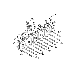
Referring to Figs. 2 - 4, the pickup and alignment mechanism for logs 10
includes
a frame 14. The frame 14 has a first rail 16, a second rail 18 and a face
plate 20. The
first rail 16 is spaced apart from the second rail 18. Desirably, the first
rail 16 is located
vertically above and away from the second rail 18. The distance the first rail
16 is spaced
apart from the second rail 18 can vary. The distance can be about 36 inches or
less.
Desirably, the distance is about 30 inches or less. The first rail 16 has a
first end 22 and
a second end 24. Likewise, the second rail 18 has a first end 26 and a second
end 28,
see Fig. 3. The first and second rails, 16 and 18 respectively, can be solid
members or
be hollow members. For example, the first and second rails, 16 and 18
respectively, can
be hollow tubular members. The cross-sectional shape of the first and second
rails, 16
and 18 respectively, can vary. The first and second rails, 16 and 18
respectively, can be
circular, square, rectangular, triangular, etc. in shape. The first and second
rails, 16 and
18 respectively, are depicted as elongated members having rectangular cross-
sections
with rounded corners.
The face plate 20 connects or joins the first rail 16 to the second rail 18.
The face
plate 20 has an upper edge 30 positioned adjacent to the first rail 16 and a
lower edge 32,
- 5 -
CA 2892434 2020-02-26
see Fig. 3, positioned adjacent to the second rail 18. The face plate 20 also
has a
rear surface 34, see Figs. 3 and 4.
The first rail 16, the second rail 18 and the face plate 20 can be constructed
from
various materials. Desirably, the first rail 16, the second rail 18 and the
face plate 20 are
all constructed out of the same material. The first rail 16, the second rail
18 and the face
plate 20 can be formed from steel, a steel alloy, metal, a metal alloy, etc.
Steel is a
preferred material for the first and second rails, 16 and 18 respectively, and
for the face
plate 20 because it is durable, malleable and is not susceptible to breaking.
Referring to Fig. 3, the pickup and alignment mechanism for logs 10 also
includes
a connector 36 secured to the face plate 20. Desirably, the connector 36 is
located on a
rear surface 34 of the face plate 20. The connector 36 allows the pickup and
attachment
mechanism for logs 10 to be physically attached to the motorized vehicle 12.
The
connector 36 including a first abutment point 38 located adjacent to the upper
edge 30 of
the face plate 20, and second and third attachment points, 40 and 42
respectively. The
second and third attachment points, 40 and 42 respectively, are spaced apart
from one
another and are located adjacent to the lower edge 32 of the face plate 20.
The first
abutment point 38 is located approximately midway between the second and third
attachment points, 40 and 42 respectively. The connector 36 is a quick
attachment that
is well known in the art.
As depicted in Fig. 3, the first abutment point 38 is depicted as an abutment
surface
that can be contacted by a flat member located on or extending forward from
the front end
of a tractor. The second and third attachment points, 40 and 42 respectively,
are depicted
as apertures. Each of the apertures 40 and 42 can receive a tongue, a hook, an
arm, etc.
For example, the two forward extending hydraulic arms on a utility tractor can
engage with
the second and third attachment points, 40 and 42 respectively. Those skilled
in the art
will be well aware of other kinds of connectors that can be used instead of
the connector
36 described above.
- 6 -
CA 2892434 2020-02-26
CA 02892434 2015-05-22
. .
Most implements which are designed to be removably connected to tractors
having wheels or tracks, a utility tractor, Bobcats , skid steer loaders, etc.
utilize some
kind of a face plate. The face plate is designed to be engaged by the two
forwardly
extending arms protruding out from the motorized vehicle. In addition, some
agricultural,
industrial and construction vehicles utilize a connector plate that is
attached to the two
forwardly extending arms and in turn engage with the face plate 20. Such
connector
plates usually abut against the first abutment point 38. Hydraulic or
pneumatic hoses
can be connected to the implement to raise, lower and/or maneuver the
implement once
it is attached to the motorized vehicle 12. Hydraulic and pneumatic cylinders,
hoses,
controls, pumps, reservoirs, fluid or air supply tanks, etc. are all well
known to those
skilled in the art.
Referring to Figs. 1 ¨ 5, the pickup and alignment mechanism for logs 10
further
includes a plurality of tines 44. Each tine 44 is an integral member. By
"tine" it is meant
a prong on an implement such as a fork or pitchfork. Desirably, two, three,
four, five, six,
seven, eight, nine, ten or more tines 44 are utilized. More desirably, an even
number of
tines 44, 44 are utilized. The tines 44 can vary in size, shape and
configuration. For
example, each tine 44 can be a horizontal member having a predetermined
geometrical
cross-section. The cross-section can vary. The cross-section can be square,
rectangular, circular, a hollow tube, etc. Each tine 44 can be removably or
permanently
secured to the frame 14 using mechanical fasteners or by welding.
Desirably, each tine 44 has an L-shaped configuration. Each L-shaped tine 44
has a horizontal portion 46 aligned approximately perpendicular, approximately
90
degrees, to a vertical portion 48, see Fig. 5. The vertical portion 48 of each
L-shaped
tine 44 can be secured to at least one, and preferably both, of the first and
second rails,
16 and 18 respectively. Desirably, each of the plurality of L-shaped tines 44
is movably
secured to the first and second rails, 16 and 18 respectively. Alternatively,
each of the
plurality of L-shaped tines 44 can be permanently secured to at least one, and
preferably
both, of the first and second rails, 16 and 18 respectively. Each of the
plurality of L-
shaped tines 44 can be movably secured in a number of ways known to those
skilled in
the art. For example, one could use mechanical fasteners, notches, apertures,
clips,
bolts, nuts, etc. to secure each of the plurality of L-shaped tines 44 to the
frame 14.
Alternatively, the vertical portion 48 of each of the plurality of L-shaped
tines 44
can be permanently or be movably secured to the first or the second rails, 16
or 18
respectively. Desirably, the vertical portion 48 of each of the plurality of L-
shaped tines
- 7 -
CA 02892434 2015-05-22
44 is movably secured to at least one of the first and second rails, 16 and 18
respectively, by using some form of mechanical fastener. The mechanical
fastener can
vary. For example, the mechanical fastener can be, but is not limited to:
nuts, wing nuts,
bolts, pins, rotatable knobs, brackets, notches, slots, grooves, apertures,
etc.
The plurality of L-shaped tines 44 can be formed from various materials. Each
of
the plurality of L-shaped tines 44 can be constructed from steel, a steel
alloy, metal, a
metal alloy, or from some other material known to those skilled in the art.
Desirably, all
of the L-shaped tines 44 are formed from the same material.
All of the L-shaped tines 44 can be constructed to the same dimensions.
Alternatively, some of the L-shaped tines 44 can be of a different dimension,
if desirous.
Desirably, all of the L-shaped tines 44 are identical in shape and size and
one can be
substituted for another. The actual dimensions of an L-shaped tine 44 can
vary. The
horizontal portion of each L-shaped tine 44 has a height h, see Fig. 5, and a
width w,
and see Figs. 4. The height h can vary and does not have to be constant along
the
length of the horizontal portion 46. Desirably, the height h will be about 2
inches at its
maximum dimension adjacent to the vertical portion 48. The width w of each L-
shaped
tine 44 can also vary. Desirably, the width w of each L-shaped tine 44 is at
least about 2
inches. More desirably, the width w of each L-shaped tine 44 ranges from
between
about 2 inches to about 4 inches. More desirably, the width w of each L-shaped
tine 44
ranges from between about 2 inches to about 3 inches. Typically, the width w
dimension
is constant along the length I of the horizontal portion 46. It has been found
that an L-
shaped tine 44 having a constant width w of about 2 inches works well.
It should be understood that a steel or metal plate could be secured between
two
adjacent L-shaped tines 44, 44, if desired, to form a more secure structure.
It is also
conceivable that one could form slots in a bucket which could then be attached
to a
motorized vehicle 12. The slotted bucket would be a variation of a pair of L-
shaped tines
44, 44 having a steel or metal plate secured thereto.
Referring again to Fig. 5, the horizontal portion 46 of each L-shaped tine 44
has
a length I and the vertical portion 48 of each L-shaped tine 44 has a height
hl. The
length I of the horizontal portion 46 can range from between about 36 inches
to about 60
inches. Desirably, the length I of the horizontal portion 46 ranges from
between about
38 inches to about 50 inches. More desirably, the length I of the horizontal
portion 46 is
about 48 inches or less. The height hl of each of the vertical portions 48 can
vary in
dimensions. The height hl of each of the vertical portions 48 can range from
between
- 8 -
CA 02892434 2015-05-22
about 20 inches to about 42 inches. More desirably, the height hl of each of
the vertical
portions 48 can range from between about 22 inches to about 36 inches. Even
more
desirably, the height hl of the vertical portion 48 can range from between
about 24
inches to about 32 inches. Most desirably, the height hl of the vertical
portion 48 can be
about 24 inches.
The length I of each of the horizontal portions 46 is greater than the height
hl of
each of the vertical portions 48. Desirably, the length I of each of the
horizontal portions
46 can be about 1.5 times greater than the height hl of each of the vertical
portions 48.
More desirably, the length I of each of the horizontal portions 46 can be
about 1.75 times
greater than the height hl of each of the vertical portions 48.
= Still referring to Fig. 5, the height h of the horizontal portion 46 of
each of the L-
shaped tines 44 taper downward towards a terminal end 50. The taper can be
constant
along the length I of the horizontal portion 46. Alternatively, the taper can
extend along
only a portion of the length I of each of the horizontal portions 46. The
maximum
dimension of the height h of each of the horizontal portions 46 occurs
adjacent to the 90
degree bend where it joins the vertical portion 48. The height h dimension at
the
terminal end 50 can range from about 0.25 inches to about 0.75 inches. A
height of
about 0.5 inches or less, works well.
Referring again to Fig. 4, ten L-shaped tines 44 is shown which are grouped
into
five pairs of tines 44, 44. The distance d between each pair of L-shaped
tines, 44, 44
can vary. The distance d between each of the pairs of L-shaped tines, 44, 44
can range
from between about 8 inches to about 20 inches. The actual dimension for the
distance
d will depend on how many pieces of firewood one wishes to obtain from each
approximately 100 inch log. For example, one could cut a 100 inch long log in
three
places and get four 25 inch lengths of firewood. Alternatively, one could cut
a 100 inch
long log in four places and get five 20 inch lengths of firewood. One could
cut a 100 inch
long log a fewer number of times or more than five times. A fewer number of
cuts would
result in longer lengths of firewood while more cuts would result in shorter
lengths of
firewood.
The distance d1 between adjacent pairs of L-shaped tines 44, 44 can also vary.
The distance d1 between adjacent pairs of L-shaped tines 44, 44 can range from
between about 2 inches to about 10 inches. Desirably, the distance dl between
adjacent
pairs of L-shaped tines 44, 44 can range from between about 3 inches to about
9 inches.
More desirably, the distance dl between adjacent pairs of L-shaped tines 44,
44 can
- 9 -
CA 02892434 2015-05-22
=
range from between about 4 inches to about 8 inches. Even more desirably, the
distance d, between adjacent pairs of L-shaped tines 44, 44 can range from
between
about 5 inches to about 7 inches. Most desirably, the distance d, between
adjacent
pairs of L-shaped tines 44, 44 is about 6 inches.
The distance d between each pair of L-shaped tines 44, 44 is greater than the
distance d, between each adjacent pair of L-shaped tines 44, 44. Desirably,
the
distance d between each of the pairs of L-shaped tines 44, 44 is more than
twice the
distance cl, between each adjacent pair of L-shaped tines 44, 44. More
desirably, the
distance d between each of the pairs of L-shaped tines 44, 44 is more than 2.5
times the
distance dl between each adjacent pair of L-shaped tines 44, 44.
For example, when eight L-shaped tines 44, each having a width w of about 2
inches, are utilized, each of the four pairs of L-shaped tines 44, 44 can be
spaced a
distance d of about 15 inches apart. The distance d, between adjacent pairs of
L-
shaped tines can be about 6 inches. This equates to (2 + 15 + 2 + 6 + 2 +15 +
2 + 6 + 2
+ 15 + 2 + 6 + 2 + 15 + 2) = 94 inches. For a log having a length of
approximately 100
inches, this leaves 3 inches extending off of each of the outer two L-shaped
tines 44, 44
(3 + 94 + 3) = 100 inches. Three cuts to a log having a length of
approximately 100
inches will render four pieces of firewood from each log. Each piece of
firewood would
be approximately 25 inches in length.
When the pickup and alignment mechanism 10 utilizes ten L-shaped tines 44,
each having a width w of about 2 inches, each of the five pairs of L-shaped
tines 44, 44
can be spaced a distance d of about 13 inches apart. The distance cl, between
adjacent
pairs of L-shaped tines 44, 44 can be about 6 inches. This equates to (2 + 12
+ 2 + 5 +
2 4- 12 + 2 + 5 + 2 + 12 + 2 + 5 + 2 + 12 + 2 + 5 + 2 + 12 + 2) = 100 inches.
For a log
having a length of approximately 100 inches, this means there would be no
overhang off
of the outermost two L-shaped tines 44, 44. Four cuts to each of the 100 inch
long logs
will render five pieces of firewood from each log. Each piece of firewood
would be
approximately 20 inches in length.
It should be understood that one could cut each log having a length of
approximately 100 inches five times to obtain six pieces of firewood from each
log. Each
piece of firewood would be approximately 16.65 inches in length.
It should also be understood that the pickup and alignment mechanism for logs
10 can use various numbers of L-shaped tines 44, 44 and the distances d and d,
can
vary to accommodate the length of firewood one desires to obtain. If one
desired to cut
- 10 -
firewood, each having a length of about 18 inches, then each of the L-shaped
tines 44,44
could be moved closer together. In addition, extra L-shaped tines 44, 44 can
be added to
the frame 14, if needed. Likewise, one or more of the L-shaped tines 44, 44
could be
removed from the frame 14 if one wanted to cut longer lengths of firewood.
Referring again to Figs. 1 - 4, the pickup and alignment mechanism for logs 10
also includes a pair of side tines 52, 52. Each of the pair of side tines 52,
52 is connected
to a cylinder 54. The cylinder 54 can be a hydraulic cylinder, a pneumatic
cylinder 54 or
some other kind of pressurized cylinder known to those skilled in the art. The
cylinder 54
can be actuated to simultaneously move the pair of side tines 52, 52 towards
or away from
one another. Alternatively, each side tine 52 can be connected to its own
cylinder 54 so
that it can move independent and/or sequentially from the other side tine 52.
Each of the pair of side tines 52, 52 can vary in configuration. As depicted,
each
of the pair of side tines 52, 52 has an L-shaped configuration. A pair of
cylinders 54, 54,
see Figs. 3 and 4, is shown which can activate the pair of side tines, 52, 52.
Alternatively,
a single cylinder 54 could be utilized to activate the pair of side tines 52,
52, if desired.
The cylinder(s) 54, 54 can be operated hydraulically, pneumatically, or by
some other way
known to those skilled in the art. Hydraulic cylinders work well. One of the
pair of side
tines 52, 52 is positioned adjacent to the first end 26 of the second rail 18
and the other of
the pair of side tines 52, 52 is positioned adjacent to the second end 28 of
the second rail
18. Desirably, each of the pair of side tines 52, 52 is vertically positioned
between the first
and second rails, 16 and 18 respectively. Desirably, each of the pair of side
tines 52, 52
is spaced from between 0 to about 6 inches above the horizontal portion 46 of
each of the
L-shaped tines 44, 44. At 0 inches, each of the pair of side tines, 52, 52 is
level with the
horizontal portion 46 of each of the L-shaped tines 44, 44. More desirably,
each of the
pair of side tines 52, 52 is spaced about 2 to about 3 inches above the
horizontal portion
46 of each of the L-shaped tines 44, 44.
The pair of side tines 52, 52 operates such that each tine 52, 52 will move
inward
toward and outward away from the other side tine 52 by the same distance and
at the
same time when connected to a single cylinder 54. In other words, the pair of
side tines,
52, 52 can move simultaneously. The pair of side tines 52, 52 functions to
align the logs
that have been picked up by the plurality of L-shaped tines 44, 44 of the
pickup and
alignment mechanism for logs 10. By activating the pair of side tines 52, 52
to move
toward one another, the logs positioned on the plurality of tines 44 will be
aligned into a
- 11 -
CA 2892434 2020-02-26
=
row such that the ends of the logs are approximately aligned relative to one
another.
When two cylinders 54, 54 are utilized, the pair of side tines 52, 52 can be
actuated to
move independent of one another.
Referring to Fig. 6, five logs 53 are shown positioned on the plurality of L-
shaped
tines 44, 44. The logs 53 can vary in diameter. Typically, the diameter of the
logs 53
will range from between about 2 inches to about 25 inches. Desirably, the
diameter of
the logs 53 will range from between about 4 inches to about 20 inches. More
desirably,
the diameter of the logs 53 will range from between about 6 inches to about 16
inches.
If the diameter of a log 53 becomes too great, the piece of firewood may have
to be split
one or more times so that it will fit into a fireplace, a wood burning
furnace, a stove, etc.
Referring again to Fig. 3, the pickup and alignment mechanism for logs 10 also
includes one or more hoses 56, 56. A pair of hoses 56, 56 is shown being
permanently
connected to each of the cylinders 54, 54. The pair of hoses 56, 56 can be
connected to
hydraulic, pneumatic or some other type of connectors (not shown) which are
located in
or on the motorized vehicle 12. When hydraulic fluid is utilized, the
motorized vehicle 12
will have a fluid reservoir that is connected to a fluid pump such that
pressurized
hydraulic fluid can be routed to the hydraulic connectors. When connected, the
pair of
hoses 56, 56 will allow pressurized hydraulic fluid to be supplied to the
single cylinder 54
or to each of the cylinders 54, 54, when two cylinders 54, 54 are utilized.
The movement
of the pressurized hydraulic fluid into and out of the cylinder 54, or into
and out of the
two cylinders 54, 54, will actuate a piston (not shown) present in each of the
cylinders
54. Hydraulic fluid is the desired fluid for activating the cylinders 54, 54
since many
tractors, Bobcat , and skid steer loaders are equipped with a hydraulic
reservoir.
However, pressurized air can also be used, if desired.
It should be noted that when a pair of hoses 56, 56 are utilized, one hose 56
can
be connected to one end of the cylinder 54 and the other hose 56 can be
connected to
the opposite end of the cylinder 54. As pressurized hydraulic fluid or
pressurized air is
introduced to a first end of the cylinder 54, pressurized hydraulic fluid or
air will exit the
second end of the cylinder 54. This action will cause the piston located
within the
cylinder 54 to move back and forth. A piston rod secured to the piston will
extend out of
the cylinder 54 and be connected to one of the pair of side tines 52, 52. As
the piston
rod moves outward from the cylinder 54, it will cause the side tine 52 to
swing inward.
Likewise, as the piston rod moves inward into the cylinder 54, it will cause
the side tine
52 to swing outward.
- 12 -
CA 2892434 2020-07-09
CA 02892434 2015-05-22
=
Referring again to Figs. 1 - 5, the pickup and alignment mechanism for logs 10
further includes a number of bumpers 58. When ten L-shaped tines 44, 44 are
present,
five bumpers 58 will be present. If only eight L-shaped tines 44, 44 are
present, only
four bumpers 58 will be needed. Each bumper 58 is positioned between each of
the
pairs of L-shaped tines 44, 44. Each bumper 58 is movably secured to the
vertical
portion of each of the pairs of the L-shaped tines 44, 44. The bumpers 58, 58
can be
mechanically attached using bolts and nuts or some other form of mechanical
fastener
known to those in the art. Each of the bumpers 58 is spaced apart from an
adjacent
bumper 58. Desirably, the distance between adjacent bumpers 58, 58 is about
the
same. The bumpers 58, 58 function to provide clearance such that a person with
a saw,
such as a chain saw (not shown), can cut the approximately 100 inch long logs
53
positioned on the plurality of L-shaped tines 44, 44 without contacting the
frame 14 with
the blade of the chain saw. In other words, the bumpers 58, 58 provide a space
or
clearance between the frame 14 and the log 53 resting adjacent to it.
In Fig. 4, five bumpers 58, 58 are shown. Each of the five bumpers 58 is
spaced
apart from an adjacent bumper 58 by a distance dz. The distance dz can be the
same
between all of the adjacent bumpers 58. Alternatively, the bumpers 58, 58 can
be
spaced different distances dz apart. The five bumpers 58, 58 provide clearance
such
that a person with a chain saw (not shown) can cut the logs 53 positioned on
the plurality
of L-shaped tines 44, 44 without contacting the frame 14 with the blade of the
chain saw.
The bumpers 58 can be formed from any known material. Such materials
include, but are not limited to: steel, a steel alloy, metal, a metal alloy,
wood, rubber,
plastic, thermoplastic, composites, closed or open cell foam, etc. In
addition, a bumper
58 could be constructed from a soft material, such as a piece of pine wood.
Another
option is to cover the soft material with a thin metal plate having a
thickness of about
1/16 of an inch or larger, to make it stronger.
Referring again to Fig. 2, each of the bumpers 58, 58 has a length 11, a width
and a thickness tl. The length 11, the width w1, and the thickness t1 can all
vary in
dimension. The length 11 of each bumper 58 will partially depend on the
overall size or
height hl of the vertical portion 48 of each of the plurality of L-shaped
tines 44, 44. The
length l of each bumper 58 is measured parallel to the height hl of the
vertical portion
48. The length l of each bumper 58 can be greater than, equal to or be less
than the
height h1 of the vertical portion 48 of each of the plurality of L-shaped
tines 44, 44.
Desirably, the length l of each of the bumpers 58, 58 will be equal to the
height hl of the
- 13 -
CA 02892434 2015-05-22
vertical portion 48 of each of the plurality of L-shaped tines 44, 44. More
desirably, the
length l of each of the bumpers 58, 58 will be at least about 30% of the
height hl of the
vertical portion 48 of each of the plurality of L-shaped tines 44, 44. Even
more desirably,
the length l of each of the bumpers 58, 58 will be equal to at least about 50%
of the
height hl of the vertical portion 48 of each of the plurality of L-shape tines
44, 44.
Normally, the length I of each of the bumpers 58, 58 can range from between
about 4
inches to about 24 inches. Desirably, the length l of each of the bumpers 58,
58 is
between about 6 inches and 20 inches. More desirably, the length l of each of
the
bumpers 58, 58 is between about 8 inches and 18 inches.
The width wl of each of the bumpers 58, 58 will be determined by the distance
d
that a pair of L-shaped tines 44, 44 is spaced apart from one another. The
width wl of
each of the bumpers 58, 58 should bridge across the distance d and include the
width w
of a pair of the L-shaped tines 44, 44. For example, if a pair of L-shaped
tines 44, 44,
each having a width w of about 2 inches, is spaced apart a distance d of about
13 inches
apart, then the width wl of each of the bumpers 58, 58 should be (2 inches +
13 inches +
2 inches) = 17 inches. The width wl of each of the bumpers 58, 58 can range
from
between about 12 inches to about 24 inches.
Each of the bumpers 58, 58 also has a thickness tl. Typically, the thickness
t1 of
each of the bumpers 58, 58 can range from between about 3 inches to about 12
inches.
Desirably, the thickness t1 of each of the bumpers 58, 58 can range from
between about
4 inches to about 10 inches. More desirably, the thickness t1 of each of the
bumpers 58,
58 can range from between about 4 inches to about 8 inches. The thickness t1
is
important for it provides a buffer between the tip of the chain saw blade and
the frame
14. Since the frame 14 is constructed from steel or metal, if the chain saw
blade should
contact it, the blade of the chain saw could be damaged. Each of the bumpers
58, 58
functions to provide a clearance between the frame 14 and the blade of the
chain saw
such that damage to the blade is prevented or minimized.
Still referring to Fig. 4, each of the bumpers 58, 58 is spaced apart from an
adjacent bumper 58 by a set distance d2. The distance d2 can vary. The
distance d2 can
range from between about 4 inches to about 10 inches. Desirably, the distance
d2 will
range from between about 4 inches to about 8 inches. More desirably, the
distance d2
will be about 6 inches.
Referring again to Fig. 2, the pickup and alignment mechanism for logs 10 also
includes a plurality of electrical switches 60 which are located on or in the
cab of the
- 14 -
CA 02892434 2015-05-22
motorized vehicle 12. The number of electrical switches 60 can vary. By
flipping or
turning on each electrical switch 60, one can activate a corresponding
solenoid valve 62.
The solenoid valves 62 can be secured to the motorized vehicle 12 as well.
Each
solenoid valve 62 will be connected to one of the cylinders 54, 54. In
addition, one or
more of the solenoid valves 62 can be connected to the cylinders which control
the
movement of the two forwardly extending arms (not shown) of the motorized
vehicle 12.
The two forwardly extending arms (not shown) can be attached to the face plate
20 so
as to control the raising, lowering and tilting of the pickup and alignment
mechanism for
logs 10.
It should be understood that the electrical switches 60 are electrically
connected
to each of the solenoid valves 62, although not shown. Furthermore, each of
the
solenoid valves 62 is connected to a respective cylinder 54. A hydraulic motor
or a
pneumatic pump can also be utilized, if needed. The physical hose making this
connection is not shown since this is well known in the art.
Referring again to Fig. 6, the pickup and alignment mechanism 10 is designed
to
operate such that the plurality of L-shaped tines 44, 44 can be maneuvered to
pickup
from between one to six logs 53 at a time. The logs 53 are each about 100
inches (8.3
feet) in length and some are in contact with the ground. For example, the logs
53 can be
aligned parallel to one another and be stacked in an approximately triangular
shaped
pile. The logs 53 can be picked up and raised a desired distance above the
ground.
This distance can vary but usually ranges from between about 6 inches to about
24
inches. The pair of side tines 52, 52 can be activated to longitudinally align
the logs 53
relative to one another to form a single row of logs 53. The ends of each log
53 will be in
contact with the pair of side tines 52, 52 or be slightly spaced inward
therefrom. The
logs 53 are aligned in a single row on the plurality of L-shaped tines 44, 44.
In other
words, the logs 53 that have been picked up are not in a stack or bundle but
instead are
aligned essentially parallel to one another. In this configuration, the logs
53 can be
individually cut at a number of different locations so that each of the logs
53 will be cut to
create a number of individual pieces of firewood sized to fit into a log
burning furnace, a
stove, a fireplace, a camp fire, etc. In Fig. 6, each of the six logs 53 can
be cut by a
chain saw or by a hand saw at four spaced apart locations. This results in
five pieces of
firewood per log or 5 x 6 logs = 30 pieces of firewood. The four cuts produce
five 20
inch long pieces of firewood from each approximately 100 inch long log 53.
- 15 -
t
In Fig. 6, each of the approximately 100 inch logs 53 is cut into a number of
pieces
of firewood each having a predetermined length. The logs 53 can be
individually cut by a
person with a chain saw or a hand saw. The logs 53 can be raised from about 6
inches
to about 24 inches off the ground by the pickup and alignment mechanism 10, so
that the
person with the chain saw or hand saw can walk up to the logs 53, and without
having to
bend down to ground level, easily and comfortably cut each log 53. Each log 53
can be
cut in four separate locations which yields five pieces of firewood. The
person with the
chain saw or hand saw is not required to bend over to the same extent as when
the logs
53 are lying on the ground. This makes it more comfortable for the person with
the saw.
The diameter of each log 53 can vary but usually the harvested logs 53 have a
diameter
of from between about 2 inches to about 25 inches. Furthermore, the logs 53
are cut while
being positioned on the plurality of L-shaped tines 44, 44 which are raised
above the
ground. This means that the blade of the chain saw or hand saw will not
contact the
ground and become dull or be damaged. The five cut pieces of firewood from
each
approximately 100 inch long log 53 will remain stationary on one of the five
pairs of L-
shaped tines 44, 44. The five cut pieces of firewood from each approximately
100 inch
long log 53 will not fall off of the pairs of L-shaped tines 44, 44 after
being cut. The cut
pieces of firewood can then be transported to a storage area by the motorized
vehicle 12
and can be off loaded and/or stacked in a sheltered area. The person or
persons off
loading the cut pieces of firewood do not have to bend over to pick up each
piece of
firewood. Instead, the cut pieces of firewood can be raised to a desired
height by the
pickup and alignment mechanism 10 so that the person simply has to move the
pieces of
firewood laterally. This makes the job easier and quicker with less bending
and lifting.
Alternatively, the cut pieces of firewood can be transported to a wagon and/or
be raised
so that the pieces of firewood can be dumped into the wagon without any
physical labor.
It should be understood that the pickup and alignment mechanism 10 can be
tilted
forward and/or backward by the connector 36 such that the plurality of L-
shaped tines 44,
44 can be angled above horizontal, be horizontally aligned, or be angled below
horizontal.
The number of degrees that the plurality of L-shaped tines 44, 44 can be
tilted can vary.
This angle can range from between about + 45 degrees to ¨ 45 degrees from the
horizontal position.
Referring now to Figs. 7 ¨ 11, a second embodiment of a pickup and alignment
mechanism for logs 10' is shown. In this embodiment, like numerals refer to
similar
elements as were shown in Figs. 1 - 6. This pickup and alignment mechanism 10'
differs
- 16 -
CA 2892434 2020-02-26
CA 02892434 2015-05-22
from the previously disclosed pickup and alignment mechanism 10 in that it
includes a
first chain saw 64, a second chain saw 66, and a third chain saw 68. In
addition, the
pickup and alignment mechanism 10' uses eight L-shaped tines 44, 44 instead of
ten,
and therefore needs only four bumpers 58, 58. Each of the first, second and
third chain
saws, 64, 66 and 68 respectively, can be a typical chain saw having a chain
saw blade
70 that can vary in length. Each chain saw blade 70 should be at least 36
inches in
length. More desirably, each chain saw blade 70 should be at least 48 inches
in length.
Even more desirably, each chain saw blade 70 should be at least 60 inches in
length.
Most desirably, each chain saw blade 70 is greater than 60 inches. All three
chain saws
64, 66 and 68 can be of the same length.
Referring to Fig. 8, each of the first, second and third chain saws, 64, 66
and 68
respectively, is pivotably mounted to the frame 14. The exact method of
attachment can
vary. For example, all three of the chain saws 64, 66 and 68 can be mounted on
a
single horizontal shaft. Alternatively, each of the three chain saws 64, 66
and 68 can be
individually mounted to the frame 14 on a separate shaft. In Fig. 8, each of
the first,
second and third chain saws, 64, 66 and 68 respectively, is individually
mounted to the
frame 14. Each of the first, second and third chain saws, 64, 66 and 68
respectively,
can be pivoted by use of a hydraulic, pneumatic or some other type of cylinder
72 known
to those skilled in the art. Desirably, the cylinder 72 is a hydraulic
cylinder. As
pressurized fluid or air is routed to a first end of the cylinder 72, it
causes a piston (not
shown), located within the cylinder 72, to move in an opposite direction. A
piston rod 74
attached to the piston extends out of the cylinder 72 and is coupled to one of
the three
chain saws 64, 66 or 68 via a linkage 76. As the piston rod 74 extends
outward, it
causes the linkage 76 to move, which in turn causes one of the three chain
saws 64, 66
or 68 to pivot. The use of various cams, linkages, etc. for causing each of
the three
chain saws 64, 66 and 68 to pivot are well known to those skilled in the art.
The first, second and third chain saws, 64, 66 and 68 respectively, are
positioned
between each of the four pairs of L-shaped tines 44, 44 with the third chain
saw 68 being
located between in the middle between the first and second chain saws, 64 and
66
respectively. Each of the first, second and third chain saws, 64, 66 and 68
respectively,
can be electrically started in the motorized vehicle 12 by using an electrical
switch 60, as
explained above. Alternatively, each of the first, second and third chain
saws, 64, 66
and 68 respectively, can be manually started. In addition, each of the first,
second and
third chain saws, 64, 66 and 68 respectively, can be operated by using
pressurized fluid
- 17 -
CA 02892434 2015-05-22
or air routed by activation of a solenoid valve 62, as was explained above
regarding
operation of the hydraulic or pneumatic cylinders 54, 54.
Each of the three chain saws, 64, 66 and 68 respectively, can have a blade 70
which is of the same length. Alternatively, one or two of the chain saws 64,
66 and 68
respectively, can have a blade 70 which is shorter or longer than the blade 70
of the
remaining chain saw. Desirably, all three chain saws 64, 66 and 68 have blades
70, 70
and 70 of the same length, as is shown in Figs. 7 and 8.
Referring now to Figs. 9 and 10, the first chain saw 64 is started or turned
on via
one of the electrical switches 60 and this activates one of the solenoid
valves 62. With
the first chain saw 64 running and with from one to six logs 53, each having
an overall
length of about approximately 100 inches (about 8.3 feet), positioned on the
plurality of
L-shaped tines 44, 44, the first chain saw 64 is pivoted downward by the
cylinder 72, see
Fig. 10. The logs 53, (not shown) will be bunched up into a triangular or
three-sided
profile by the grappling member 78 as will be explained shortly. As the blade
70 of the
.. first chain saw 64 is lowered, it will come into contact with the upper
most log 53 or with
the log 53 located farthest from the bumper 58. The blade 70 of the first
chain saw 64
will cut through the one to six logs 53 and create one to six pieces of
firewood each
having a length of approximately 25 inches. Each of the individual pieces of
firewood
will remain on the left outermost pair of L-shaped tines 44, 44. The "left"
set of L-shaped
tines 44, 44 are located on the left when one views Fig. 9.
Still referring to Fig. 9, after all of the one to six logs 53 have been cut
by the first
chain saw 64, the first chain saw 64 is moved or pivoted back to its initial
starting
position, as is shown in Fig. 7. At this time, the second chain saw 66 is
started or turned
on via one of the electrical switches 60 and this activates one of the
solenoid valves 62.
.. With the second chain saw 66 running and with from one to six logs 53
positioned on the
plurality of L-shaped tines 44, 44, the second chain saw 66 is pivoted
downward by its
cylinder 72. This action will allow the blade 70 of the second chain saw 66 to
come into
direct contact with the upper most log 53 or the log 53 located farthest from
the bumper
58. The blade 70 of the second chain saw 66 will cut through the logs 53 and
create one
to six pieces of firewood each having a length of approximately 25 inches.
Each of the
individual pieces of firewood will remain on the right outermost pair of L-
shaped tines 44,
44. The "right" set of L-shaped tines 44, 44 are located on the right when one
views Fig.
9.
- 18 -
CA 02892434 2015-05-22
Still referring to Fig. 9, after all of the logs 53 have been cut by the
second chain
saw 66, the second chain saw 66 is moved or pivoted back to its initial
starting position,
as is shown in Fig. 7. At this time, the third or middle chain saw 68 is
started or turned
on via one of the electrical switches 60 and this activates one of the
solenoid valves 62.
With the third chain saw 68 running and with from one to six logs 53
positioned on the
plurality of L-shaped tines 44, 44, the third or middle chain saw 68 is
pivoted downward
by its cylinder 72. This action will allow the blade 70 of the third chain saw
68 to come
into direct contact with the upper most log 53 or the log located farthest
from the bumper
58. The blade 70 of the third chain saw 68 will cut through the one to six
logs 53 and
create two additional pieces of firewood from each log 53, with each piece of
firewood
having a length of approximately 25 inches. Each of the individual pieces of
firewood
will remain on the middle two pairs of L-shaped tines 44, 44.
After all of the logs 53 have been cut by the third chain saw 68, the third
chain
saw 68 is moved or pivoted back to its initial starting position, as is shown
in Fig. 7. This
sequential action by the first, second and third chain saws, 64, 66 and 68
respectively,
creates four pieces of firewood from each of the logs 53. Therefore, if six
logs 53 where
positioned on the plurality of L-shaped tines 44, 44, then after the three
cuts, one would
have (6 logs x 4 pieces) = 24 pieces of firewood with each piece of firewood
having a
length of approximately 25 inches. The twenty-four pieces of firewood can then
be
transported to a storage area, collection site, wagon, etc. as was explained
above.
It should be understood that one or more conduits (not shown) can be present
which route pressurized fluid or air between the motorized vehicle 12 and each
of the
first, second and third chain saws, 64, 66 and 68 respectively. The
pressurized fluid or
air is used to operate each of the first, second and third chain saws, 64, 66
and 68
respectively. Desirably, the pressurized fluid is a hydraulic fluid.
Referring again to Figs. 7 - 11, the four bumpers 58, 58, 58 and 58 provide
clearance so that each of the first, second and third chain saws, 64, 66 and
68
respectively, can completely cut through each of the one to six logs 53
positioned on the
plurality of L-shaped tines 44, 44. The plurality of L-shaped tines 44, 44 can
be
maneuvered to pickup from between one to six logs 53 at a time, as was
described
above, and raise the logs 53 a desired distance above the ground. The pair of
side tines
52, 52 can be activated to longitudinally align the one to six logs 53
relative to one
another so that they can be cut to a desired length by the first, second and
third chain
saws, 64, 66 and 68 respectively. The first, second and third chain saws, 64,
66 and 68
- 19 -
CA 02892434 2015-05-22
respectively, are sequentially operated such that the first chain saw 64 will
make a cut
through each of the one to six logs 53 positioned on the eight L-shaped tines
44, 44.
The second chain saw 66 will then make a cut through each of the one to six
logs 53
positioned on the eight L-shaped tines 44, 44. Lastly, the third or middle
chain saw 68
will make a cut through each of the one to six logs 53 positioned on the eight
L-shaped
tines 44, 44. By using this sequence, one does not have to worry about the
third chain
saw 68 binding or getting pinched between the logs 53 it is cutting through.
Still referring to Figs. 7 ¨ 11, the pickup and alignment mechanism 10' also
differs from the first embodiment 10 in that it includes a pair of grappling
members 78
and 80. By "grapple" it is meant the act of grappling, to grasp or grip. The
grappling
member 78 can be identical in construction to the grappling member 80.
Alternatively,
each grappling member 78 and 80 can be different in construction. Desirably,
each of
the grappling members 78 and 80 are identical in construction. Each of the
pair of
grappling members 78 and 80 can vary in size, construction and design. As
illustrated,
each of the pair of grappling members 78 and 80 is an arcuate, ladder like
member
which is pivotably mounted to the frame 14. Each of the pair of grappling
members 78
and 80 includes a cylinder 82. Each cylinder 82, 82 can be actuated
hydraulically,
pneumatically or in some other fashion well known to those skilled in the art.
Desirably,
the cylinders 82, 82 are hydraulically operated. Each of the cylinders 82, 82
can be
activated using an electrical switch 60 positioned in the motorized vehicle
12, as
explained above. In addition, each of the cylinders 82, 82 can be operated by
using
pressurized fluid or air routed by activation of a solenoid valve 62, as was
also explained
above.
Each of the pair of grappling member 78 and 80 further includes a first
linkage
84, see Fig. 9, connecting the piston rod of each cylinder 82, 82 to a portion
of the
arcuate, ladder like member, and a second linkage 86 connecting the opposite
end of
the cylinders 82, 82 to the frame 14. The exact configuration of the first and
second
linkages, 84 and 86 respectively, can vary.
The pair of grappling members 78 and 80 is located on either side of the third
or
middle chain saw 68. The pair of grappling members 78 and 80 function to
retain the
one to six logs 53 in a bunched or three-sided configuration on the plurality
of L-shaped
tines 44, 44. The pair of grappling members 78 and 80 also functions to hold
the one to
six logs 53 stationary so that they can be sequentially cut by the first,
second and third
chain saws, 64, 66 and 68 respectively. The pair of grappling members 78 and
80 would
- 20 -
CA 02892434 2015-05-22
be raised to an open or upward position, see Fig. 7, when the pickup and
alignment
mechanism 10' is brought into contact with a pile of logs 53 positioned on the
ground.
After one to six logs 53 are positioned on the plurality of L-shaped tines 44,
44, the pair
of grappling members 78 and 80 can be closed or lowered downward (not shown)
so as
to hold the logs 53 steady on the plurality of L-shaped tines 44, 44.
The pair of grappling members 78 and 80 will remain in the closed or downward
position as the first, second and third chain saws, 64, 66 and 68
respectively,
sequentially cut each of the one to six logs 53. The location of the pair of
grappling
members 78 and 80 does not interfere with the operation of the first, second
and third
chain saws, 64, 66 and 68 respectively. The pair of grappling members 78 and
80 can
be opened or moved to the upward position when the cut pieces of firewood are
to be off
loaded. It should be noted that each of the grappling members 78 and 80 can
move
independent of the other grappling member. Alternatively, both of the
grappling
members 78 and 80 can be designed to move as a unit.
Referring now to Fig. 12, a side view of the pickup and alignment mechanism
10'
is shown with the grappling member 78 in a down position holding six logs 53,
arranged
in an approximately three-sided polygon configuration, stationary. With the
pickup and
alignment mechanism 10', the logs 53 are grouped together by the grappling
members
78 and 80, while with the pickup and alignment mechanism 10, the six logs 53
are
aligned adjacent to one another in a single row.
It should be understood that the one to six logs 53 will be held stationary by
the
grappling members 78 and 80. The configuration of the logs 53 will vary
depending on
how many logs 53 are retained by the grapping members 78 and 80. If only one
log 53
is picked up, it would be retained against the bumpers 58, 58. If two logs 53,
53 are
picked up, they can be positioned side by side or with one above the other. If
three,
four, five or six logs 53 are picked up, they could form a three-sided
polygon. The three-
sided polygon can be a right angled triangle, an equal lateral triangle or
some other
geometrical configuration. Since the logs 53 can have different diameters, can
taper
along their lengths, are not perfectly straight, can contain knots, stubs of
branches, forks,
can contain various kinds of bark, etc., the configuration of the logs 53 can
form various
geometrical shapes.
Referring now to Figs. 13 - 17, a third embodiment of a pickup and alignment
mechanism for logs 10" is shown. In this embodiment, like numerals refer to
similar
elements as were shown in Figs. 1 - 6. The pickup and alignment mechanism 10"
differs
- 21 -
CA 02892434 2015-05-22
=
from the second previously disclosed pickup and alignment mechanism 10' in
that it
includes ten L-shaped tines 44, 44, similar to what is shown in Figs. 1 ¨ 6.
In addition,
the pickup and alignment mechanism 10" utilizes four chain saws and a single
grappling
member. The four chain saws include a first chain saw 64, a second chain saw
66, a
third chain saw 68 and a fourth chain saw 69. The third and fourth chain saws,
68 and
69 respectively, are positioned between the first and second chain saws, 64
and 66
respectively. Each of the four chain saws 64, 66, 68 and 69 has a chain saw
blade 70.
The four chain saws 64, 66, 68 and 69 should be operated sequentially to
prevent one of
the chain saw blades 70 from becoming wedged or pinched as a cut is being
made.
Desirably, the first chain saw 64 will cut the one to six logs 53 and then be
raised back
up to its initial position shown in Fig. 13. The second chain saw 66 will then
make its cut
through the one to six logs 53 and then be raised up to its initial position.
The third chain
saw 68 will then make its cut through the one to six logs 53 and then be
raised up to its
initial position. Lastly, the fourth chain saw 69 will make its cut through
the one to six
logs 53 and then be raised up to its initial position.
The pickup and alignment mechanism 10" contains a single grappling member
78 which can be constructed to be identical to that described in Figs. 7 ¨ 12.
The
grappling member 78 is an arcuate, ladder like member which is pivotably
mounted to
the frame 14. The grappling member 78 includes a cylinder 82. Desirably, the
cylinder
82 is operated by a hydraulic fluid, although a pneumatic or some other type
of cylinder,
known to those skilled in the art, could also be used. The cylinder 82 can be
activated
using an electrical switch 60 positioned in the motorized vehicle 12, as
explained above.
In addition, the cylinder 82 can be operated by using pressurized fluid or air
routed by
activation of a solenoid valve 62, as was also explained above. The grappling
member
78 further includes a first linkage 84 connecting the piston rod of the
cylinder 82 to a
portion of the arcuate, ladder like member, and a second linkage 86 connecting
the
opposite end of the cylinder 82 to the frame 14. The exact configuration of
the first and
second linkages, 84 and 86 respectively, can vary.
The grappling member 78 is located between the third and fourth chain saws, 68
and 69 respectively. The grappling member 78 functions to retain the one to
six logs 53
in an approximate three-sided polygon configuration on the plurality of L-
shaped tines
44, 44, as was explained above with reference to Fig. 12. The grappling member
78
also functions to hold the one to six logs 53 in a stationary fashion so that
they can be
sequentially cut by the first, second, third and fourth chain saws, 64, 66, 68
and 69
- 22 -
CA 02892434 2015-05-22
respectively. The grappling member 78 starts out in an open or upward
position, see
Fig. 13. The pickup and alignment mechanism 10" then engages with from one to
six
logs 53 so that they are positioned in a generally parallel fashion on the
plurality of L-
shaped tines 44, 44. The grappling member 78 is then closed or lowered
downward (not
shown) such that it contacts the log 53 or logs 53 and holds them stationary.
The grappling member 78 will remain in the closed or downward position as the
first, second, third and fourth chain saws, 64, 66, 68 and 69 respectively,
sequentially cut
each of the one to six logs 53. The location of the grappling member 78 does
not
interfere with the operation of the first, second, third and fourth chain
saws, 64, 66, 68
and 69 respectively. The grappling member 78 can be opened or moved to the
upward
position when the cut pieces of firewood are to be off loaded.
Referring now to Fig. 17, one will notice that the middle two L-shaped tines
44,
44 and the attached bumper 58 are raised vertically relative to the frame 14.
It should
be understood that the middle two L-shaped tines 44, 44 are attached to their
own frame
member 14' so that they can be raised vertically relative to the remaining L-
shaped tines
44, 44. The movable frame 14' can be actuated using hydraulic or pneumatic
pressure.
By raising the two middle L-shaped tines 44, 44, the ends of each of the logs
53, 53
positioned thereon can sag. This sagging helps to prevent the logs 53, 53 from
binding
or pinching against the blades 70, 70 of the third and fourth chain saws, 68
and 69
respectively. This is important when the grappling member 78 is utilized.
Since the
grappling member 78 is exerting a downward force on the logs 53, by raising
the center
portion of each log 53, the logs 53 can be cut without binding or pinching the
blades 70,
70 of the third and fourth chain saws, 68 and 69 respectively. The middle two
L-shaped
tines 44, 44 needs only be raised a small amount. The middle two L-shaped
tines 44, 44
can be raised from between about 2 inches to about 8 inches to prevent binding
of the
chain saw blades 70, 70. Desirably, the middle two L-shaped tines 44, 44 are
raised
from between about 3 inches to about 6 inches to prevent binding of the chain
saw
blades 70, 70.
It should be understood that the third and fourth chain saws, 68 and 69
respectively, are also raised relative to the frame 14. The third and fourth
chain saws,
68 and 69 respectively, are secured to the movable frame 14' so that they can
be raised.
The movable frame 14' can vary in design and construction.
Referring now to Fig. 18, a fourth embodiment of a pickup and attachment
mechanism for logs 10" is shown. The pickup and attachment mechanism 10" is
similar
- 23 -
CA 02892434 2015-05-22
to that shown in Figs. 7 -11 except for a few differences. First, each of the
four pairs of
L-shaped tines 44, 44 is replaced by a single tine 44, each having a flat
plate 88 secured
thereto. Only four L-shaped tines 44, 44, 44 and 44 are needed in this
embodiment
instead of eight L-shaped tines 44. Each of the four plates 88 can vary in
size, thickness
and configuration. As depicted, each of the four plates 88, 88, 88 and 88 has
a
generally rectangular shape. Each of the four plates 88, 88, 88 and 88 can be
welded
onto an upper surface of each of the four L-shaped tines 44, 44, 44 and 44.
Each of the
four plates 88, 88, 88 and 88 has a width w2 which is approximately equal to
the width wl
of each of the four bumpers 58, 58, 58 and 58. Desirably, the width w2 of each
plate 88
is equal to the width wl of each bumper 58.
Another difference of the pickup and attachment mechanism 10" in Fig. 18 is
that
each of the pair of side tines 52, 52 has a vertical extension 90, 90. Each of
the vertical
extensions 90, 90 can vary in size, thickness and configuration. Each of the
vertical
extensions 90, 90 is depicted as having an approximately triangular shape,
similar to the
shape of a feather on an arrow. The vertical extensions 90, 90 assist in
keeping the logs
53 aligned, especially when one log 53 is positioned above another log 53.
When one or
more grappling members 78 and/or 80 are utilized, the logs 53 become stacked
up into
an approximately three-sided polygon configuration, for example, a triangular
configuration, see Fig. 12, instead of remaining in a single row as is shown
in Fig. 6
when no grappling member 78 or 80 is present. By bunching the logs 53 up, the
grappling members 78 and 80 are better able to hold the logs 53 stationary as
they are
being cut by the first, second and third chain saws 64, 66 and 68
respectively.
Referring now to Fig. 19, a front view of the pickup and attachment mechanism
10- is shown. One will notice that the middle two L-shaped tines 44, 44 and
the
attached bumpers plates 88, 88 and bumpers 58, 58 are secured to their own
movable
frame member 14". This frame member 14" allows these components to be raised
vertically relative to the frame 14. It should be understood that the movable
frame
member 14" can vary in design and construction. By raising the two middle
tines 44, 44
and the attached plates 88, 88, the ends of each of the logs 53, 53 positioned
thereon
will be able to sag. This sagging helps to limit or prevent the logs 53, 53
from binding or
pinching against the blades 70, 70 of the third or middle chain saws 68. This
is
important when the grappling member 78 is utilized. Since the grappling member
78 is
exerting a downward force on the logs 53, by raising the center portion of
each log 53,
the logs 53 can be cut without binding or pinching the third or middle chain
saw 68. The
- 24 -
,
middle two L-shaped tines 44, 44 and the attached plates 88, 88 are raised
from between
about 3 inches to about 6 inches to prevent binding of the chain saw blade 70.
It should be understood that the third or middle chain saw 68 is mounted to
the
movable frame 14" and therefore can be raised relative to the frame 14. The
movable
frame 14" can be actuated using hydraulic or pneumatic pressure.
In Fig. 19, the grappling member 80 is shown in a down position while the
grappling
member 78 is shown in an up position. Each grappling member 78 and 80 can be
independently actuated. In addition, one could design and construct of the
pair of side
tines 52, 52 such that each one would move independently, if desired.
It should be understood that when operating the pickup and alignment mechanism
10', 10" or 10" it will be necessary to supply lubricating oil to the blades
70 of each of the
chain saws 64, 66 and 68 or 64, 66, 68 and 69. Lubricating oil can be supplied
to each of
the blades 70 several different ways. One way is to attach an oil reservoir
(not shown) to
the frame 14, 14' or 14" and allow the oil to be directed to each of the
blades 70 by gravity.
Another way to accomplish this is to cap or close the ends of the first rail
16 and use it as
an oil reservoir. Three or four holes can be drilled in the first rail 16 and
a connecting hose
can be connected to each of the holes. Each of the connecting hoses can be
positioned
adjacent to each of the blades 70. Other ways of lubricating the blades 70 of
each of the
chain saws 64, 66 and 68 or 64, 66, 68 and 69 can also be utilized.
METHOD
A method of using the pickup and alignment mechanism 10 will now be described
so as to enable a person with a saw, desirably a chain saw, to cut each log 53
into smaller
pieces of firewood. The method includes the steps of physically mounting or
attaching the
pickup and alignment mechanism 10 to a hitch secured to a motorized vehicle
12. The
pickup and attachment mechanism 10 is also connected to a hydraulic or
pneumatic
system present on the motorized vehicle 12. It is well known to those skilled
in the art that
many tractors, such as farm tractors, Bobcats , backhoes, forklifts,
construction
equipment, as well as other kinds of utility vehicles, commonly have a
hydraulic or
pneumatic system which includes various components, such as a reservoir, a
pump, a
motor, hoses, valves, controls, etc. for supplying pressurized fluid or air to
an attached
implement. A hydraulic system is most desirable.
- 25 -
CA 2892434 2020-02-26
The motorized vehicle 12 is started to pressurize the hydraulic or pneumatic
system. The motorized vehicle 12 is then maneuvered so that the plurality of L-
shaped
tines 44, 44 will engage a pile of cut logs stacked on the ground. Each of the
logs 53 will
have a length of approximately 100 inches. The plurality of L-shaped tines 44,
44 will
contact and remove from between one to six logs 53 from the pile. The logs 53
will be
aligned approximately parallel to one another and be arranged as a single row
on the
plurality of L-shaped tines 44, 44. The logs 53 are then raised above ground
level by
elevating the plurality of L-shaped tines 44, 44 to a desired height. The logs
53 can be
raised any desired distance. Typically, the logs 53 are raised from between
about 1 inch
to a few feet above ground level. Desirably, the logs 53 are raised from
between about 6
inches to about 24 inches above ground level. More desirably, the logs 53 are
raised from
about 12 inches to about 20 inches above ground level. The motorized vehicle
12 can
then be maneuvered away from the pile of logs positioned on the ground. This
will create
room for a person with a chain saw to approach the front of the pickup and
alignment
mechanism 10 and cut each of the logs 53 into smaller pieces.
A method of using the pickup and alignment mechanisms 10', 10" and 10- differs
in that the grappling members 78 and 80 can be lowered to contact and group
the one to
six logs 53 into a three-sided polygon configuration and will hold them
stationary as the
three chains saws 64, 66 and 68, or the four chain saws 64, 66, 68 and 69,
sequentially
engage and cut the logs 53 into smaller pieces. The cut firewood can then be
transported
by the motorized vehicle 12 to a stacking or off-loading location. Here, the
grappling
members 78 and 80 are raised and the firewood can be removed from the
plurality of L-
shaped tines 44, 44.
While the invention has been described in conjunction with several specific
embodiments, it is to be understood that many alternatives, modifications and
variations
will be apparent to those skilled in the art in light of the foregoing
description. Accordingly,
this invention is intended to embrace all such alternatives, modifications and
variations
which fall within the spirit and scope of the appended claims.
- 26 -
CA 2892434 2020-02-26