Note: Descriptions are shown in the official language in which they were submitted.
CA 02892722 2015-05-27
CRASH BARRIER BEAM
This is a divisional application of Canadian Patent Application Serial No.
2,670,222
filed on November 21, 2007.
The present invention relates to a crash barrier beam and, in particular but
not
exclusively, to interlocking crash barrier beams suitable for use as a
temporary road
barrier.
It should be understood that the expression "the invention" and the like used
herein
may refer to subject matter claimed in either the parent or the divisional
applications.
Crash barriers are provided along the centre or verge of vehicle carriageways
for
restraining impacting vehicles along their length, by absorbing energy from
the
collision. Whilst permanent crash barriers are provided on motorways, for
example,
it may be desirable in some situations, perhaps during road works, to provide
temporary crash barriers to section off a part of a road or a hazard in the
road.
Permanently deployed crash barriers are designed to withstand collisions and
restrain errant vehicles, some of the impact energy being absorbed by the
supporting
posts, which are set into the ground. This is harder to achieve with temporary
crash
barriers, as it is sometimes desirable to deploy these without securing them
to the
bed of the road by pins or the like. There is also a need to balance barrier
strength
and stability with ease of assembly on site and the desire to keep costs of
manufacture and assembly down. There is therefore a need to provide an
improved
road crash barrier which can be temporarily deployed. The present invention
has
been devised with the foregoing in mind.
A known temporary road barrier shown in Figure 0 comprises a base 100 that
rests
on a road surface, the base having spaced apart posts 102 extending vertically
therefrom to a top rail 104. For vehicles such as pick-up trucks, which are
built on
chasses, the chassis rails of a pick-up truck may engage with the vertical
posts of the
known barrier on impact, causing unwanted deflection of the barrier. These
known
barriers are also expensive to manufacture and difficult to deploy.
In one aspect, there is provided a crash barrier beam, suitable for temporary
or
1
CA 02892722 2015-05-27
permanent use on a road, the beam comprising: a base for contact with the
road, a
central wall and a top section, wherein the central wall extends upwardly from
the
base and tapers from the base toward the top section, the central wall having
a
length defined by a first end and a second end, at least one of said first and
second
ends comprising formations for engagement with corresponding respective
formations on an end of another beam for interlocking the beams to one another
to
facilitate self-alignment of the beams.
It is an advantage that adjacent beams are easily joined together, without the
need
for additional tools or loose component parts (e.g. nuts and bolts).
Preferably, the first end of the beam is provided with one or more male
connectors
engageable within respective one or more female connectors provided on a
second
end of another beam. Alternatively, the first end of the beam is provided with
one or
more flanges engageable within respective slots provided on an end of the
adjacent
beam. The one or more male and female connectors / flanges and respective
slots
may be provided along substantially the height of the barrier to reduce the
risk of
adjacent housings becoming separated on impact by an errant vehicle. The ends
of
the beam may be configured such that the exterior surfaces of adjacent barrier
sections are flush with respect to each other on attachment.
It is an advantage that incorporating the male and female connectors / flanges
into
the joint between adjacent beams increases the joint stiffness and strength,
and
therefore this reduced the chance of the beam deflecting when a vehicle
impacts
thereon.
In an embodiment, the beam comprises laterally extending base portions for
supporting the beam on the road. The base portions may be provided with one or
more connectors (e.g. interengaging connectors) / flanges for engaging
respective
connectors / slots provided in the base portions of an adjacent beam.
Any or all of the male connectors may comprise a j-shaped connector engageable
within a corresponding j-shaped female connector. Conveniently, the male and
female connectors are of substantially the same configuration, and mounted in
a
mirror-image fashion on their respective beam ends with respect to each other,
so as
2
CA 02892722 2015-05-27
to be engageable within each other. This advantageously facilitates
manufacture
and construction/installation of the beam. In an embodiment, the female
connector
protrudes from the end of the housing of the first end of the beam and the
male
connector is housed substantially within the second end of the beam. The ends
of
the beam are advantageously configured such that the exterior surfaces of
adjacent
beams are flush with respect to each other on attachment.
Each of the female and male connectors may be mounted on jointing assemblies
secured at the first and/or second ends of the beam. Preferably, and
advantageously, the jointing assemblies for each of the male and female
connectors
are substantially identical. The jointing assemblies may be substantially flat
and
comprise a central plate spanning the space between the walls of the housing
and a
toe sized to fit within said cavity. Preferably, the plate and toe are
integrally formed
or fixed together. Portions of the plates may be cut away, to facilitate
energy
absorption by the beam in the event of an impact. The toes may conveniently be
formed from the cut away parts of the plate. In an alternative embodiment,
separate
toe infills may be provided to provide additional strength and rigidity to the
base of
the beam.
A first beam may be provided, at its first end, with one or more male
connectors
engageable within respective one or more female connectors provided on an end
of
another beam. The second end of the beam is preferably provided with a
jointing
assembly securable to a like jointing assembly provided on another beam.
A second beam may be provided, at its first end, with one or more female
connectors
engageable within respective one or more male connectors provided on an end of
another beam. The second end of the beam is preferably provided with a
jointing
assembly securable to a like jointing assembly provided on another beam.
A third beam may be provided, each end of which is provided with a jointing
assembly securable to a like jointing assembly provided on another beam.
The jointing assemblies of any or all of the first, second and third beams are
preferably substantially flat and comprise a central plate spanning the space
between
the walls of the housing and a toe sized to fit within said cavity. It is an
advantage
3
CA 02892722 2015-05-27
that like jointing assemblies can be utilised for each of the first, second
and third
beams. Preferably, the plate and toe are integrally formed or fixed together.
Portions of the plates may be cut away, to facilitate energy absorption by the
beam in
the event of an impact. The toes may conveniently be formed from the cut away
parts of the plate. In an alternative embodiment, separate toe infills may be
provided
to provide additional strength and rigidity to the base of the beam.
A barrier section may comprise the first beam, the second beam, and one or
more
third beams provided therebetween. The third beams may be secured together via
respective jointing assemblies. Each free end of the group of joined third
beams may
be secured with jointing assemblies to jointing members of the first and
second
beams.
A barrier may comprise a plurality of such barrier sections, the one or more
male
connectors of a first beam being engageable with the one or more female
connectors
of a second beam.
It is an advantage that a length of barrier can be constructed from any
combination of
first, second and third beams, and barrier sections, depending on the
situation. Any
number of third beam sections may be provided between the first and second
beams,
or a first beam may be connected straight to a second beam. The groups of beam
may be joined together off site (e.g. in a factory) or on site during
construction of the
barrier. A barrier may alternatively only comprise a series of third beams
joined
together.
One or more gussets may be provided where two beams are connected at their
respective jointing assemblies. The gussets advantageously provide a flow path
for
distributing force from an impact up and/or down the length of the beam and/or
barrier in the event of an impact thereon.
In an embodiment, a locking unit is provided for securing two adjacent beams
together. Preferably, the locking unit is slidable between the housings of
adjacent
beams. The beams may thus be secured together when the locking unit bridges
the
junction between adjacent beams. The locking unit may initially be completely
housed within the housing of one beam without protruding beyond the edge of
the
4
housing. Instead of, or in addition to the locking unit, an insert may be
provided within
the end of the hollow top portion, to strengthen the beam. It is an advantage
that the
stiffened top portion and the stable base strengthen the whole beam structure.
In one aspect, there is provided a crash barrier beam, suitable for temporary
or
permanent use on a road, the beam comprising: a housing which in profile has a
laterally extending base for contact with the road, a narrower central wall
and a top
section, wherein the central wall extends upwardly from the base such that the
central wall tapers from the base toward the top section, the central wall
having a
length defined by a first end and a second end, only one of said first and
second
ends comprising formations for engagement with corresponding respective
formations
on an end of another beam for interlocking the beams to one another to
facilitate self-
alignment of the beams, and wherein the beam comprises formations at one end
thereof only and the other end is provided with a jointing assembly directly
securable
to a like jointing assembly provided on another beam.
In one aspect, there is provided a crash barrier beam, suitable for temporary
or
permanent use on a road, the beam comprising: a housing which in profile has a
laterally extending base for contact with the road, a narrower central wall
and a top
section, wherein the central wall extends upwardly from the base such that the
central
wall tapers from the base toward the top section, the central wall having a
length defined
by a first end and a second end, only one of said first and second ends
comprising
formations for engagement with corresponding respective formations on an end
of
another beam for interlocking the beams to one another to facilitate self-
alignment of the
beams, and wherein the beam comprises formations at one end thereof only and
the
other end is provided with a jointing assembly directly securable to a like
jointing
assembly provided on another beam; wherein one or more gussets are provided at
the
respective jointing assemblies, said gussets providing a flow path for
distributing force
from an impact up and/or down the length of the beam in the event of an impact
thereon.
Embodiments of the invention will now be described by way of examples with
reference
to the drawings, in which:
CA 2892722 2018-04-30
Figure 0 shows end, side and underneath views of a prior art temporary crash
barrier;
Figures la and lb are isometric views of a crash barrier beam according to an
embodiment of the present invention;
Figure 2 is a representation of one half of the profile of a crash barrier
beam according to
an embodiment of the present invention;
Figures 3a and 3b are isometric views of a central crash barrier beam section
according
to an embodiment of the present invention;
Figures 4a to 4d show a female end crash barrier beam section according to an
embodiment of the present invention;
Figures 5a to 5d show a male end crash barrier beam section according to an
embodiment of the present invention;
Figures 6a and 6b show jointing plates that can be incorporated into
embodiments of the
present invention;
Figure 7a is a detailed view of the junction between the central beam of
Figures 2a and
2b and an adjacent end beam section;
Figure 7b shows a gusset that can be used at the junction shown in Figure 7a;
Figure 8 shows a locking unit that can be incorporated into embodiments of the
present
invention;
Figures 9a to 9c show, in assembled and unassembled form, a lifting point for
a crash
barrier beam according to an embodiment of the present invention;
Figure 10 shows a rubber foot that can be incorporated into embodiments of the
present
invention; and
Figure 11 shows a strengthening web that can be incorporated into embodiments
of the
present invention.
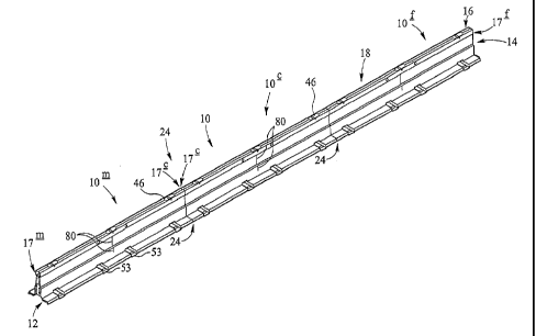
Referring to Figures la and lb, an elongate 'Zoneguard ' crash barrier beam 10
is
5a
CA 2892722 2018-04-30
CA 02892722 2015-05-27
shown. The beam 10 has a base 12 that generally extends laterally with respect
to
the length of the beam 10. A narrower central wall 14 is upwardly extending
from the
base 12. The wall 14 has a form generally of an inverted V-shape tapering
towards a
top section 16. The top section 16 preferably has a box-like cross section.
Together,
the base 12, wall 14 and top box 16 form a hollow housing 18. By way of
example,
the housing may have a height of 0.8m, the width of the largest part of the
base
being 0.6m and the top box section may have a width of 0.13m. In an
alternative
embodiment, the width of the largest part of the base is substantially 0.7m
and the
top box section is substantially 0.16m.
The beam 10 is preferably comprised of a central beam section 10c, and two end
beam sections 10m, 10f located either side thereof. In the embodiment shown in
Figures la and 1 b, ends 17c of the central beam section 10c are each provided
with
a flat joint assembly 20c secured to the housing 18 e.g. by welding. The joint
assembly 20c (see e.g. Figures 3a, 3b) is securable to a similar assembly 20c
provided at a first end 17c of an end beam section 10m/10f. In the embodiment
shown, the end assemblies 20c of the central and end beam sections 10c,
10m/10f
can be secured together with bolts 19 via corresponding apertures 22 (see also
Figures 4c and 5c) to form a joint or junction 24, as shown in Figures la, lb
and 7a.
This provides the advantage that the connecting bolts 19 are concealed (and
cannot
therefore be easily dislodged in the event of an impact or otherwise). The use
of flat
joint assemblies 20c means that the edges of the first ends 17c of the beams
10c,
10m/10f meet so that the outer surfaces of adjacent beams 10c, 10m/10f are
flush
with respect to each other.
The beam 10 of Figures la and lb is comprised of a first end beam section 10m
joined to a central beam section 10 which, in turn, is joined to a second send
beam
section 10f. A second end 17m of the first beam section 10m is configured to
interlock with a second end 17f of the second end beam section 10f. This
enables
multiple beams 10 to be secured together to form the full length of crash
barrier
required, as will be described in greater detail below.
In a preferred embodiment, the three beam sections 10m, 10c, 10f are each of
4m in
length, and joined together to form a beam 10 that is 12m in length. The
second end
17m of the first end beam section 10m is provided with male connectors
interlockable
6
CA 02892722 2015-05-27
with corresponding female connectors on the second end 17f of the second end
beam section 10f (or the male/female connectors may be provided on the
second/first end beam 10f/10m). This allows one beam 10 comprising three such
beam sections 10m, 10c, 10f to be connected to another beam comprising another
three such beam sections 10m, 10c, 10f. In another preferred embodiment, the
three
beam sections 10m, 10c, 10f are each of 5.08m (16.67 feet) in length, and
joined
together to form a barrier section 15.24m (50 feet) in length.
It will be appreciated that other configurations of beam sections with flat
joint
assemblies and/or interlocking connectors can also be utilised. In an
alternative
embodiment (not shown), there is no central beam section 10c, but two end
sections,
a male beam section 10m and a female beam section 10f, are joined together at
their
first ends 17c via assemblies 20c in a manner similar to that described above
and are
interlockable at their second ends 1 7m, 17f via interengaging connectors.
Each
beam section 10m, 10f may have a length of 7.5m and so the barrier section 10
has
a length of about 15m. It will further be appreciated that other beam lengths
are
contemplated, for example in the range 5-10m. Alternatively, a plurality of
central
beam sections 10c could be provided between end male and female sections Om,
10f, or a single beam section could be provided with a male connector at one
end
and a female connector at the other end.
Referring now to Figure 2, the overall profile of half of the housing 18 is
shown in
cross section, the other half being substantially a mirror image (considering
manufacturing tolerances etc.).
The base 12 comprises an outwardly extending flange 12a relative to the length
of
the beam 10) that is generally flat or inclined at a small angle to the
horizontal. At its
outermost limit, the base 12 is shaped such as to extend downwardly 12c and
then
back towards the central axis A-A of the housing 10, to form a cavity 13. The
lowermost part 12b of the base 12 is substantially horizontal for placement on
a road
(B). The lowermost (and outermost) corner 12c of the base 12 is formed at an
angle
that will allow a vehicle wheel to ride up onto the base flange 12a.
The central wall 14 extends generally upwardly from the base flange 12a such
that a
lower portion 14a of the wall 14 extends at a relatively steep angle with
respect to the
7
CA 02892722 2015-05-27
base 12a. An upper portion 14b of the wall extends at approximately the same
angle
towards the top box 16. A step or shoulder 14c is provided between the lower
wall
portion 14a and the upper wall portion 14b, the step 14c providing a jump or
discontinuity in the gradient of the otherwise planar wall 14. At the top of
the upper
wall portion 14b, the housing 18 extends outwardly, away from the central axis
A-A,
to form another step or lip 15. This is also shown in Figures la and lb, which
additionally shows that the lip 15 runs along the length of the beam 10. In
the
embodiment shown in Figure 2, the angles of the shoulder 14c and lip 15 with
respect to the horizontal are symmetrically opposite, and preferably shallow
with
respect to the horizontal. This provides for ease of manufacture. In an
alternative
embodiment (not shown), the angle of the shoulder 14c is steeper with respect
to the
horizontal than that of the lip 15.
By way of example, the step 14c may extend a distance of about 15mm between
the
upper and lower walls 14, 14b and the lip 15 may extend a distance of about
15mm
between the upper wall 14b and the top box section 16.
The housing 18 then widens from the upper wall 14b into the top portion 16.
The
hollow housing 18 is preferably formed in two halves, a left skin as shown in
Figure 3
and a mirror-image right skin (not shown). Together, the two halves form a
substantially symmetrical housing 18. The half-profiles of the housing 18 are
shaped
from (e.g. by bending or pressing) a sheet of material (e.g. metal and
preferably
steel) into the formation previously described. That is to say, each half-
profile is a
single, integrally formed, unit. At the centre 16a of the top portion 16,
means (not
shown) may be provided for linking the two halves of the profile together. In
a
preferred embodiment, the two skins are welded together. Alternatively, the
housing
18 could be constructed as a single integral component.
An advantage of using sheets of metal to form the housing 18 is that the lip
15 and
shoulder 14c that are bent into the sheet to profile the housing 18 add
strength to the
structure, without the need to add additional strengthening members, for the
sheet/panel half-profile.
Several housings 18 and/or beams 10 may be stacked top-to-tail next to each
other,
i.e. by inserting one inverted housing 18 / beam 10 between two adjacent
upright
8
CA 02892722 2015-05-27
housings 18 / beams 10. Instead or as well, the housing shells (i.e. with no
or few
additional component parts provided internally thereof) may be configured to
be
stacked vertically on top of and within one another.
Referring to Figures 3a and 3b, a 'central' beam section 10c is shown. The
central
beam section 10c is provided at each end 17c with a jointing assembly 20c. The
jointing assembly 20c of the central beam section 10c is attachable to a
jointing
assembly 20c of either a male end beam section 10m or a female end beam
section
101. That is to say, the jointing assemblies 20c provided at each end of the
central
beam section 10c are substantially the same (i.e. within manufacturing
tolerances),
and they are also substantially the same (i.e. within manufacturing
tolerances) as the
jointing assemblies 20c of the male/female beam section 10m, 10f to which the
central beam section 10c is to be attached. In an alternative embodiment (not
shown), two or more beam sections 10c may be joined together using jointing
assemblies 12c with end beam sections 10m, 101 provided at either end thereof,
to
create a larger sectional barrier.
As mentioned above, the end beam sections 10m, 10f are configured to interlock
with
each other. Conveniently, the end beam sections 10m, 10f are provided (at the
second ends thereof) with complementary male and female members that are inter-
engageable with each other.
Figures 4a to 4d show the features of the 'female' end beam section 10f. The
second end 171 of the female beam section 10f is provided with longitudinal
connecting members 32 provided along the extremity of the wall portion 14 of
the
housing 18. The members 32 are j-shaped in cross-section, there being a
channel
33 therewithin. The j-shaped members 32 extend along the majority of the
length the
wall 14. It is convenient to use two connectors 32 on each upwardly extending
side
of the wall 14, one provided on the lower wall portion 14a and one on the
upper wall
portion 14b, but any number of connectors 32 may be provided. Additional j-
shaped
connecting members 34 are provided along the lower surface of the base flange
12a.
Figure 4d shows a side view of the female end beam section 10f, from which it
can
be seen that the connectors 32, 34 protrude longitudinally beyond the end of
the
housing 18. The connectors 32, 34 do not, however, protrude laterally beyond
the
edge of the housing 18.
9
CA 02892722 2015-05-27
The connectors 32, 34 of the female beam section 10f are bolted to the joint
assembly 20f with bolts 19 via apertures 22. The joint assembly 20f may be
welded
within housing 18 to secure it in place therewithin.
Figures 5a to 5d show the 'male' end beam section 10m. The male beam section
10m is provided with longitudinal connecting members 38 along the extremity of
the
wall portion 14 of the housing 18, as shown in Figures 5a and 5b. The
connecting
members 38 are j-shaped in cross-section, there being a channel 39
therewithin.
The channels 39 of the j-shaped members 38 are sized to receive the connectors
32
of a female beam section 10f. The connectors 38 extend along the majority of
the
length the wall 14 and two members 38 are provided on each upwardly extending
side of the wall 14, one provided on the lower wall portion 14a and one on the
upper
wall portion 14b. Additional j-shaped longitudinal members 40 are provided
along the
lower internal surface of the base flange 12a.
The connectors 38, 40 of the male beam section 10m are bolted to the joint
assembly
20m with bolts 19 via apertures 22. The joint assembly 20m is welded within
housing
18 to secure it in place therewithin. The connectors 38, 40 of the male beam
section
10m do not protrude longitudinally beyond the end of the housing 18. Thus, the
male
connectors 38, 40 are housed within the housing 18.
Each of the male and female connectors 32, 38 are of substantially the same
configuration, but oriented symmetrically and in a mirror-image manner with
respect
to each other. That is to say, the connectors 32, 38 of the male and female
beam
sections 10m,10f respectively are mutually receivable within each other, to
secure
the two adjacent beam sections 10m, 10f together. The channel 33 of a female
beam section 10f can receive the free end of the j-shaped member 38 of a male
beam section 10m and, simultaneously, the channel 39 of the male beam section
lOrn can receive the free end of the j-sh aped member 32 of the female beam
section
10f.
Each of the additional connectors 34, 40 are also of substantially the same
configuration, arranged in opposite orientations on each of the male and
female
beam sections 10m, 10f. In the embodiment shown in Figures 4a-4d and 5a-5d,
the
CA 02892722 2015-05-27
channel formed by the j-shaped member 40 of the male beam section 10m opens
downwardly and the channel formed by the j-shaped member 34 of the female beam
section 101 opens upwardly. The j-shaped members 34, 40 are mutually
receivable
within each other, in a similar manner as previously described for the j-
shaped
members running along the wall 14 of the housing 18.
In an embodiment, the base j-shaped members 34, 40 may be shaped specifically
to
fit the left-hand and right-hand female beam section 101 as shown in Figure 4b
and
the left-hand and right-hand male beam section 10m as shown in Figure 5b.
Alternatively, although not shown in the Figures, the same base j-shaped
members
34, 40 may be used in each of these situations.
The j-shaped connectors 32, 34, 38, 40 are preferably formed from steel. It is
desirable to coat the connectors 32, 34, 38, 40 with Geomet or another
similar
product. The Geomet coating advantageously provides for a more rapid
changeover of damaged components compared with galvanised components. This
is because, in the event of an impact on a barrier with galvanised components,
there
is a tendency for the components to adhere to each other ¨ due to the back
shock
from the impact. This can make replacing damaged components difficult. By
contrast, Geomet has a low coefficient of friction, which means that, in the
event of
an impact, back shock does not cause the components to stick together ¨ thus
facilitating replacement of damaged parts. Furthermore, the process of coating
components with Geomet is environmentally friendly, since Geomet contains no
hexavalent chromium, and it is also applied by baking it on to steel
components at
low temperatures. A further advantage is that Geomet coatings are thinner (6-
8
microns) than galvanised coatings. The various fixings (e.g. screws, nuts,
bolts,
washers) utilised in the construction of the barrier may also be coated with
Geomet
for the same reasons.
Figure 6a shows a joint assembly 20c for provision at either end of a central
beam
section and/or at the first end of the male and female beam section 10m/10f.
The
joint assembly 20c comprises a central joint plate member 23c and two toes
25c.
The central joint member 23c is joined to the toes 25c, preferably by welding.
The
outer profile of the joint assembly 20c substantially corresponds to the
interior hollow
of the housing 18. That is to say, the central plate 23c fills the space
between the
11
CA 02892722 2015-05-27
walls 14 and the top section 16. The toes 25c fill the cavities 13. When a
central
beam section 10c and a male/female beam section 10m/10f are joined together,
their
respective plates 23c are bolted together using bolts through the apertures
22. The
plates 23c, which are welded around their edges to the interior of the housing
18,
also provide a means for preventing the two halves of the housing 18 from
disengaging. Advantageously, the same central joint member 23c can be used for
each of the central beam sections 10c and the first ends of the male and
female
beam sections 10m, 10f. The central joint 23c is also symmetrical about axis A-
A
(see Figure 2), meaning that it can be used either way round with respect to
the axis
A-A, thus facilitating installation within the housing.
Figure 6b shows a joint assembly 20m, 20f for provision at the second end 17m,
17f
of a male/female beam section 10m, 10f. The joint assembly 20m, 20f is similar
to
that of the central beam section 101, with a central joint plate member 23m,
23f and
two toes 25m, 251. The central member 23m, 23f is again joined to the toes
25m,
25f, preferably by welding. The outer profile of the assembly 20m, 20f
substantially
corresponds to the interior hollow of the housing 18. That is to say, the
central plate
23m, 231 fills the space between the walls 14. The toes 25m, 25f fill the
cavities 13.
However, there is no plate section to fill the top box part 16 of the housing
18.
Advantageously, the same central joint member 23m, 23f can be used for each of
the
second ends of the male and female beam sections 10m, 10f. It is symmetrical
about axis A-A (see Figure 2), meaning that it can be used either way round
with
respect to the axis A-A, thus facilitating installation within the housing.
The toes 25c, 25m, 25f are common to each of the central, male and female beam
sections 10c, 10m, 101. It is thus convenient that the same toes 25c, 25m, 25f
can
be welded to each of the central joint members 23c and 23m, 23f.
The central plates 23c, 23m, 23f are partially cut away to provide openings
27c, 27m,
27f. This aids in keeping the mass of the plates 23c, 23m, 231 down. It also
enables
the barrier to crumple in the event of an impact thereon, to absorb energy
therefrom,
so as to ensure the barrier is not too stiff to cause a danger in the event of
an impact.
The toes 25c, 25m, 25f may be manufactured from the portion of material
removed to
form the opening 27c, 27m, 27f in the plate 23c, 23m, 23f.
12
CA 02892722 2015-05-27
Figure 7a shows the junction 24 between ends 17c of a central beam section 10c
and an end beam section 10m. The joint assemblies 20c of each beam section
10c,
10m are bolted together with bolts 19. Gussets 21 are provided to reinforce
the
connection between the two beam sections 10c, lOnn, and to create a flow path
to
dissipate load/force up and down the barrier in the event of an impact. As can
be
seen from Figure 7b, the gussets 21 are generally triangular in shape, with
tabs 21t
that fit into slots 21j in the joint assemblies and slots 21h in the housing
18. The
central beam section 10c is joined to a female beam section 10f in the same
way as
described above for joining the male beam section 10m to the central beam
section
10c.
It is very convenient that each of the male and female connectors for adjacent
beams
are formed from commonly shaped component parts (the jointing plate 23m, 23f
and
the j-shaped connectors 32, 38.
The interlocking between a male beam section 10m and a female beam section 10f
is such that on attempting to engage a male beam section 10m with a female
beam
section 101, the beam sections 10m, 10f are substantially self-aligning with
respect to
each other. Since the female connectors 38, 40 protrude from the end of the
housing
18 and the male connectors 32, 34 are housed within the housing 18, the
external
surfaces of the housings 18 of joined beam sections 10m, 10f are substantially
flush.
The self-aligning, end-to-end engagement of adjacent beam sections 10m, 101
provides the advantage that no tools are required in the joining thereof, and
no loose
component parts are required to fix them together. In order to connect the two
beam
sections 10m, 101 together, the male beam section 10m is lifted onto the
connectors
32 of the female beam section 101. Since the base 12 of the male beam section
10m
is wider than the upper parts 14, 16 of the female beam section 10f, there is
no need
to accurately locate one onto the other ¨ the female connectors 32, 34 and
male
connectors 38, 40 will tend to locate themselves with respect to each other.
Once in
position, the male and female wall connectors 32, 38 interlock and the male
and
female base connectors 34, 40 interlock. The two sets of male / female
connections
ensure that the beam sections 10m, 101 are laterally and vertically positioned
correctly with respect to each other. Furthermore, additional barrier strength
is
13
CA 02892722 2015-05-27
provided on interlocking male and female beam sections 10m, 10f because the
joint
stiffness is increased.
Furthermore, since the connectors 32, 34, 38, 40 are simply bolted onto the
joint
assemblies 20m, 20f, the connectors 32, 34, 38, 40 are easy to replace if
necessary,
and a wide range of connectors 32, 34, 38, 40 of various shapes and sizes can
be
interchanged between different beam sections, for example. This also allows
alternative interfaces to be fitted, such as to provide attachment to other
components
such as crash cushions etc. Furthermore, these components are simple and
inexpensive to manufacture.
Figure 8 shows a locking unit 70, which may be provided within the open ends
of the
box section 16 of adjacent male and female beam sections 10m, 10f. The locking
unit 70 is configured to bridge the join of adjacent male and female beam
sections
10m, 10f, to aid alignment thereof and to retain them in their correct
positions. The
locking unit 70 comprises a location member 72 and a guidance member 74
connected via legs 76. Conveniently, the locking unit 70 sits fully within the
top box
section 16 of a female beam section 10f and, when a male beam section 10m is
placed adjacent thereto, the locking unit 70 is slidable into the top box
section 16 of
the male beam section 10m. The locking unit then bridges the top box sections
16 of
the male and female beam sections 10m, 10f.
The location member 72 is u-shaped in cross section, and the legs 76 are
attached to
each free end of the u-shaped location member 72. The guidance member 74 is
attached to the free ends of the legs 76 and extends upwardly, perpendicular
with
respect to the legs 76. The location member 72 comprises opposing surfaces
72a,
the corners 72b of which are chamfered to assist in auto-alignment with an
adjacent
male beam section 10m. The upstanding guidance member 74 protrudes through an
aperture 48 in the housing of the female beam section 10f (see Figure 3a). The
aperture 48 is elongate, and the guidance member 74 can be moved along the
length
of the aperture 48 to move the locking member 70 from a position in which it
is fully
retracted within the female beam section 10f to a position in which it bridges
adjacent
male and female beam sections 10m, 20f.
Referring to Figures la, 3a, 4a and 5a, lifting points 46 are shown, provided
in the
14
CA 02892722 2015-05-27
uppermost portion 16a of the top box housing 16. Each lifting point 46 is
configured
so that a hook, chains, ropes etc. can be attached thereto, for lifting the
beam
sections 10c, 10m, 10f into and out of position on the road or otherwise.
The lifting point 46 comprises the aperture 48 in the uppermost surface of the
top box
section 16. A lifting bar 50 extends laterally outwardly with respect to the
central axis
A-A of the beam section 10c, 10m, 10f. The bar 50 is located within the top
box
section 16, and secured to the opposing sides thereof e.g. by bolts, studs 52
or the
like. The concealment of the lifting point 46 within the box section 16
reduces the
likelihood of damage to impacting vehicles and reduces the likelihood of
damage by
a vehicle to the lifting point 46. The lifting bar 50 further adds strength to
the box
section 16, and aids in preventing crushing of the box section in the event of
an
impact. The lifting bar 50 also acts as a stop for movement of the locking
unit 70, to
prevent the locking unit being pushed too far out of the female beam section
10f.
As can be seen form Figure la, three lifting points 46 are provided spaced
along the
length of each of the beam sections 10c, 10m, 101. When the three beam
sections
10c, 10m, 101 are joined together (as in Figure 1a), the beam 10 will have
nine lifting
points 46. The lifting points 46 may be configured for use with multiple forms
of lifting
and handling equipment. In the embodiment shown, each beam section 10c, 10m,
10f may be lifted by the central lifting point 46, as a pivot during assembly
to level the
beam section 10c, 10m, 10f and to lift over obstacles such as hills etc.
In an alternative embodiment (not shown) comprising two beam sections
connected
to provide male and female connectors at the ends thereof, each of the two
beams
may again be provided with lifting points 46. For example, two lifting points
46 may
be provided spaced along the length of each beam section, providing four
lifting
points for the assembly. In this embodiment it is convenient to lift the
barrier using
the inner lifting points 46 of the outer two beams, as this enables the beam
to be
lifted by just two lifting points 46, whilst spanning the majority of the
length of the
assembled beams. It will be appreciated that any number of lifting points may
be
provided on at least one, some or all of the beam sections 10c, 10m, 10f.
Referring to Figures 9a, 9b and 9c, a lifting insert 54 is shown. This insert
54 is
designed to be secured (preferably by welding) within a drainage channel 53
(as
CA 02892722 2015-05-27
shown in Figures la and 2a, for example). The drainage channels 53 are
provided in
the base 12, extending through the full lateral width of the beam 10. These
allow
water to pass from one side of the barrier to the other.
The insert 54 has a passage 57 defined by a base 55 underneath a central
bridge 59,
the passage 57 extending from one side of the insert 54 to the other and
therefore,
when welded into the base 12 of a beam section 10c, 10m, 10f, from one side of
the
beam section 10c, 10m, 10f to the other. The beam section 10c, 10m, 101 may be
lifted from its upright position by a fork lift truck, the fork(s) being
insertable into either
side of the passage 57 of the lifting insert 54.
An aperture 58 is provided in the base 55 of the lifting insert 54. When in
its inverted
form, a beam section 10c, 10m, 10f may be lifted using a lifting dog that
passes
through the aperture 58. Alternatively, the insert 54 may be provided with
tongues
(not shown) that are welded to and extend outwardly from each side of the
central
bridge 59 of the insert 54, in the direction of the length of the beam section
10c, 10m,
10f. The tongues facilitate centring of lifting straps or chains and to ensure
that the
lifting straps/chains do not slip during lifting. The tongues therefore ensure
that the
beam section 10c, 10m, 101/ beam 10 is maintained in a stable position during
lifting
thereof. Alternatively, the tongues 58 are provided only on one side of the
insert 54.
This provides the advantage that the overall insert can be used in either
orientation
within the housing by simply rotating it by 1800, saving materials in
production whilst
still providing guide means for lifting where needed.
Lifting the beam section 10c, 10m, 101 or beam 10 via the inserts 54 allows
the beam
sections 10c, 10m, 10f or beam 10 to be lifted from an inverted position or a
position
in which it is lying on its side. The insert 54 may be constructed from a
single box
section. However, in the embodiment shown in Figure 9a, the insert 54 is
manufactured from a long piece of metal to form the lower part 55 of the
insert 54,
and a shorter piece of metal 59 welded on top of the lower piece 55.
Production in
this way is more efficient, as simply shaped pieces of metal may be used,
meaning
that there is little wastage in production.
Apertures 56 are also provided in the insert 54, for optionally anchoring the
barrier to
a road or other surface. Preferably, the apertures 56 are elongate (e.g.
slots) in a
16
CA 02892722 2015-05-27
direction transverse to the direction of the lifting insert 54 (i.e. run
parallel with the
longitudinal direction of the road). The slots 56 allow for expansion and/or
contraction of the road due to temperature fluctuations that cause the road
surface to
expand/contract.
The inserts 54 are preferably formed from metal, such as steel, and are
preferably
galvanised. Apertures 59a are provided in the bridge 59, for galvanising
drainage
during manufacture of the lifting insert 54. The inserts 54 advantageously
provide
the functions of providing means 53 for drainage and means for lifting the
beam
sections 10c, 10m, 10f (from an upright position using a fork lift truck or
from any
other position using lifting dogs/straps/chains), as well as strengthening the
base 12
of the beam sections 10c, 10m, 10f.
Referring again to Figure 1 b, the underside of a beam 10 is shown. Rubber
feet or
pads 60 (as also shown in Figure 10) may be provided on the underside of the
insert
54, for contacting the road surface. The rubber feet 60 are preferably bonded
directly
to the metal insert 54, to ensure maximum strength of the connection
therebetween.
The rubber feet 60 extend the lateral width of the housing 18, and increase
the
frictional grip of the beam 10 with the road surface, to minimise deflection
of the
barrier on impact from a vehicle (in comparison to a metal surface being in
contact
with the road surface). Furthermore, the rubber feet 60 minimise the chance of
the
beam sinking in to the road surface, as they act to spread the load of the
barrier and
reduce the pressure applied to the road by and through the barrier at the
points of
contact therebetween. This is particularly so in hot climates. Attaching
rubber feet
60 to the underside of the inserts also raises the height of the barrier with
respect to
the road surface, thus improving drainage, and minimise the chance of water
corroding the metal barrier.
The rubber pads 60 as shown in Figure 10 are injection moulded, single-piece
rubber
pads. Recesses 61 of varying shapes and thicknesses are provided within the
rubber pads. The recesses 61 help to ensure good contact with the road
surface,
even though there might be debris such as stones loose on the road that may
otherwise reduce the contact of a flat rubber surface with the road. Apertures
56a,
58a, corresponding to the apertures 56, 58 in the feet 54 are also provided.
17
CA 02892722 2015-05-27
Figure 11 shows a strengthening web 62, which is provided within the cavity
defined
by the opposing walls 14 of the housing 18 (as shown in Figures lb and 3b).
The
web 62 is sized to fit the internal profile defined by the opposing walls of
the housing
18, this being dictated by the lower and upper walls 14a, 14b and the shoulder
14c.
The web 62 provides additional stiffness to the profile, and supports the
sidewalls 14
in the event of an impact. In the embodiment shown in Figure 11, cut-outs 63
are
provided within the web 62, similar to those provided in the joint assembly
plates 23c,
23m, 231. This aids in keeping the mass of the plates webs 62 down. It also
enables
the barrier to crumple in the event of an impact thereon, to absorb energy
therefrom,
so as to ensure the barrier is not too stiff to cause a danger in the event of
an impact.
In an embodiment, and as shown for example in Figures la, lb, 3a and 3b,
cavities
or apertures 80 may be provided within the housing 18, allowing access to the
interior of the housing. This enables a person manufacturing the beam sections
10,
10' to weld the web 62 within the housing from outside the housing 18.
Various references have been made above to fixing components together with
bolts.
It is desirable to use ScotchgripTM resin, or a similar product, on the bolts.
The
ScotchgripTM resin is a two-part adhesive, which is mixed together when the
bolt is
being screwed into place. Providing the holes into which a bolt is being
screwed with
a countersink aids in the mixing by providing a surface against which the two
parts
can be pressed. This creates an adhesive on the threads of the bolts to
provide
additional strength to the fixings.
In use, the crash barrier beam sections 10m, 10c, 101 are joined together by
fixing
together adjacent central and end plates 20c, 20m; 20c, 20f at ends 17c
thereof
and/or a plurality of beams 10 are interlocked at corresponding ends 17m, 17f
thereof
which mate together as described above. The resulting structure (referred to
from
now on as the barrier) is placed on a road, by lifting the individual beam
sections 10c,
10m, 10f and/or beams 10 as discussed earlier and securing them together on
site.
The barrier is thus particularly suited to temporary use, for example at road
works, to
cordon off a particular area of road or divide vehicle carriageways for
contraflows etc.
The combined weight of the individual barrier beam sections 10c, 10m, 101 and
beams 10 act together to stabilise the barrier in the desired position.
Furthermore,
18
CA 02892722 2015-05-27
the relative sizes of the base 12 to the central walled portion 14 and top
portion 16
provide stability to the lengths of beams/barrier, thus providing a lesser
'working
width in comparison to known temporary road barriers. That is to say, the
beams 10
have a wide base onto which a vehicle wheel can ride, but the lateral width
that the
'fence' part of the beam 10 occupies is smaller. The beam sections 10c, 10m,
10f/beams 10 have a low centre of gravity, resulting in a reduced net gain in
energy
by an impacting vehicle when it rolls over the base 12. This arrangement
provides
the further advantage that the barrier may be deployed closer to traffic lanes
than
barriers with wider bases. In the embodiment shown in the Figures, the centre
of
gravity is very low (about 0.32m above the ground), due to the presence of
more
material below the centre of gravity than above it. This is achieved by the
provision
of the cutout apertures 27c, 27m, 27f in the jointing assemblies 20c, 20m,
20f. It has
been found that the beam remains stable (i.e. does not topple or roll over)
when tilted
to substantially 48 with respect to the vertical. This arrangement helps stop
the
barrier overturning in the event of a vehicle impacting upon it.
The turnover 12c of the metal sheet to form the cavity 13 provides additional
stiffness
to the barrier, and the toes 25c, 25m, 25f help maintain the turnover profile.
The
turnover 12c further reduces the pressure loading on the road surface, for
example, if
the rubber feet 60 are not provided.
In the event of an impact, one or more wheels of a vehicle approaching the
barrier
will ride up onto the base 12 of the housing 18. The weight of the vehicle
provides an
additional down force on the base 12, thus providing further stability to the
barrier in
the event of an impact. The stepped profile given to the housing 18 by the
shoulder
14c not only helps to stiffen the wall 14 of the housing 18, it assists in
redirecting a
wheel of a vehicle that is riding up the barrier. In the event that a vehicle
wheel rolls
all of the way up the sidewall 14 to contact the top lip 15, the wheel will be
redirected
back towards the ground to restrain the impacting vehicle in the carriageway.
The
combined action of the shoulder 14c and the lip 15 act to urge the vehicle
wheel back
into the carriageway, away from the barrier.
Advantageously, the profile of the beam sections 10c, 10m, 10f and the length
of
engagement of the interlocking male and female connectors 32, 38 mean that the
barrier must be lifted to a significant height before any joint disengagement
will occur.
19
CA 02892722 2015-05-27
The locking member 70 further aids in keeping adjacent male and female beam
sections 10m, 10f joined together.
Furthermore, in the event of a vehicle drifting into the barrier, e.g. if the
driver of the
vehicle is tired, the initial contact with the wide base 12 may be sufficient
to warn the
driver to take action to avoid full collision with the barrier.
It will be appreciated by persons skilled in the art that various
modifications may be
made to the above-described embodiments without departing from the scope of
the
present invention. It will also be appreciated that the features described
herein may
be taken separately and in any and all combinations in order to provide a
barrier that
is tailored for a particular use. Furthermore, whilst embodiments of the
present
invention are particularly suited for use as a temporary crash barrier, it
will be
appreciated that the beam sections/beams could also be permanently fixed to
the
road surface.