Note: Descriptions are shown in the official language in which they were submitted.
CA 02892865 2015-05-22
PLUMBING OUTLET BOX WITH MOUNTING FEATURES
FIELD OF THE INVENTION
The present invention relates generally to plumbing outlet boxes, such as
outlet
boxes for connecting washers, ice makers, and other equipment to plumbing
systems.
BACKGROUND
Conventional plumbing outlet boxes are typically used as housings for
connections to plumbing systems. A plumbing outlet box may be provided, for
example,
for connecting a washing machine to pipes running within the walls of a
building that are
designed to carry water (e.g., hot and cold water supply and drain
connections). As
another example, a plumbing outlet box may be provided to connect an ice maker
of a
refrigerator to a water supply. Plumbing outlet boxes are generally installed
in the walls
of a house or other climate-controlled building. Often more than one plumbing
outlet box
is needed in the same area, each with the capability of connecting to
different appliances
having different configurations and requirements.
Accordingly, there is a need in the art for plumbing outlet boxes and related
attachment devices that can be configured to accommodate different types of
connections and are easy to install, separately and in combination with other
plumbing
outlet boxes.
BRIEF SUMMARY OF EXAMPLE EMBODIMENTS
An assembly of plumbing outlet boxes, such as for connecting washing machines,
ice makers, and other plumbed appliances to plumbing systems, are therefore
provided
that can be attached to one another. In some embodiments at least a first
plumbing
outlet box and a second plumbing outlet box may each be configured for
mounting within
a wall. Each plumbing outlet box may include a housing including a top wall, a
bottom
wall, first and second side walls, and an opening providing access into an
interior of the
housing. A first connector may be disposed on the top wall. A second connector
may be
disposed on the bottom wall. In some embodiments, the plumbing outlet box
assembly
may include a bracket defining a plurality of engaging portions. In some
embodiments,
the second plumbing outlet box housing may be configured to be engaged with
the first
plumbing outlet box housing via engagement of a first engaging portion of the
bracket
with the first connector of the first plumbing outlet box and via engagement
of a second
engaging portion of the bracket with the second connector of the second
plumbing outlet
- 1 -
CA 02892865 2015-05-22
-
box, such that the first plumbing outlet box may be engaged with the second
plumbing
outlet box via the bracket.
In some embodiments, the bracket may be further configured to engage the
second connector of the first plumbing outlet box and the first connector of
the second
plumbing outlet box. The bracket may be configured to engage a stud such that
the
bracket may be configured to attach the first plumbing outlet box and the
second
plumbing outlet box to the stud. In some embodiments, the bracket may further
include a
built-in fastening feature, such that the bracket may be configured to engage
the stud with
the built-in fastening feature.
In some embodiments, at least one of the first connector and the second
connector may define a receiving channel configured to receive a corresponding
one of
the first engaging portion or the second engaging portion of the bracket. The
at least one
of the first connector and the second connector may define a plurality of
offset tabs
defining the receiving channel therebetween.
The bracket may define a projection on the corresponding one of the first
engaging portion or the second engaging portion configured to engage the at
least one of
the first connector and the second connector.
In some embodiments, at least one of the first plumbing outlet box and the
second
plumbing outlet box may define one or more mounting tabs configured to engage
the at
least one of the first plumbing outlet box and the second plumbing outlet box
to a stud.
In another embodiment, a plumbing outlet box may be provided that may be
configured for mounting within a wall. The plumbing outlet box may include a
housing
including a top wall, a bottom wall, a first side wall, and a second side
wall. The plumbing
outlet box may further include an opening providing access into an interior of
the housing.
In some embodiments, the plumbing outlet box may include a first connector
disposed on
the top wall. The plumbing outlet box may additionally or alternatively
include a second
connector disposed on the bottom wall. The first connector may be configured
to engage
a bracket via a first engaging portion of the bracket and the second connector
may be
configured to engage the bracket via a second engaging portion of the bracket.
The
plumbing outlet box may be configured to engage a second plumbing outlet box
via the
bracket.
The plumbing outlet box may be configured to be at least partially supported
by
the connectors such that the bracket may be configured to engage a stud to
attach the
plumbing outlet box to the stud. In some embodiments, at least one of the
first connector
and the second connector may define a receiving channel configured to receive
a
corresponding one of the first engaging portion or the second engaging portion
of the
bracket. The at least one of the first connector and the second connector may
define a
- 2 -
CA 02892865 2016-09-09
plurality of offset tabs defining the receiving channel therebetween. The at
least one of
the first connector and the second connector may be configured to engage a
projection of
the bracket.
In some embodiments, the plumbing outlet box may include one or more mounting
tabs configured to engage a stud.
Yet another example embodiment may include a bracket for mounting a plumbing
outlet box within a wall. In some embodiments, the bracket may include a
plurality of
engaging portions. A first engaging portion may be disposed proximate a first
end of the
bracket. A second engaging portion may be disposed proximate a second end of
the
bracket. In some embodiments, the bracket may be configured to engage a first
connector of a first plumbing outlet box with the first engaging portion. The
bracket may
be configured to engage a second connector of a second plumbing outlet box
with the
second engaging portion, such that the bracket may be configured to engage the
first
plumbing outlet box with the second plumbing outlet box.
In some embodiments, the bracket may be configured to engage a stud such that
the bracket may be configured to attach the first plumbing outlet box and the
second
plumbing outlet box to the stud. The bracket may further include a built-in
fastening
feature, such that the bracket may be configured to engage the stud with the
built-in
fastening feature. The built-in fastening feature may include a pointed
fastening feature
integrally formed with the bracket.
In some embodiments, the bracket may define a projection on at least one of
the
first engaging portion or the second engaging portion configured to engage the
at least
one of the first Connector and the second connector.
The bracket may include a third engaging portion disposed proximate one of the
first end or the second end of the bracket. The third engaging portion may be
configured
to engage a third connector of the first plumbing outlet box via the third
engaging portion.
In another embodiment, an assembly of plumbing outlet boxes is provided that
comprises at least a first plumbing outlet box and a second plumbing outlet
box each
configured for mounting within a wall, and each comprising: a housing
including a top
wall, a bottom wall, first and second side walls, and an opening providing
access into an
interior of the housing, wherein a first connector is disposed on the top
wall, and wherein
a second connector is disposed on the bottom wall; and a bracket defining a
plurality of
engaging portions, wherein the bracket is a single piece I-shaped bracket
having
respective first engaging portions located at a top end and respective second
engaging
portions located at a bottom end, wherein the second plumbing outlet box
housing is
configured to be engaged with the first plumbing outlet box housing via the
bracket, and
wherein one of the respective first engaging portions of the bracket is in
engagement with
- 3 -
CA 02892865 2016-09-09
the first connector of the first plumbing outlet box and the other respective
first engaging
portion of the bracket is in engagement with the first connector of the second
plumbing
outlet box, and one of the respective second engaging portions of the bracket
is in
engagement with the second connector of the first plumbing outlet box and the
other
respective second engaging portion of the bracket is in engagement with the
second
connector of the second plumbing outlet box.
In another embodiment, a bracket for mounting a plumbing outlet box within a
wall
is provided, the bracket comprises a single piece l-shape having a plurality
of engaging
portions, wherein respective first engaging portions are disposed on a top end
of the
bracket, wherein respective second engaging portions are disposed on a bottom
end of
the bracket, wherein one of the respective first engaging portions of the
bracket is
configured to engage a first connector of a first plumbing outlet box and the
other
respective first engaging portion of the bracket is configured to engage a
first connector of
a second plumbing outlet box, and wherein one of the respective second
engaging
portions of the bracket is configured to engage a second connector of the
first plumbing
outlet box and the other respective second engaging portion of the bracket is
configured
to engage a second connector of the second plumbing outlet box.
BRIEF DESCRIPTION OF THE DRAWINGS
Having thus described the invention in general terms, reference will now be
made
to the accompanying drawings, which are not necessarily drawn to scale, and
wherein:
FIG. 1 shows a perspective view of an assembly of plumbing outlet boxes in
accordance with an example embodiment of the present invention;
FIG. 2 shows a partial view of a plumbing outlet box showing a connector in
accordance with an example embodiment of the present invention;
FIG. 3 shows a bracket in accordance with an example embodiment of the
present invention;
- 3a -
CA 02892.865 2015-05-22
FIG. 4 shows a perspective view of an assembly of plumbing outlet boxes in
accordance with another example embodiment of the present invention;
FIG. 5 shows a bracket in accordance with another example embodiment of the
present invention;
FIG. 6 shows a perspective view of a housing of a plumbing outlet box in
accordance with another example embodiment of the present invention;
FIG. 7 shows a perspective view of an assembly of plumbing outlet boxes in
accordance with another example embodiment of the present invention;
FIG. 8 shows a perspective view of a housing of a plumbing outlet box in
accordance with another example embodiment of the present invention; and
FIG. 9 shows a perspective view of an assembly of plumbing outlet boxes in
accordance with another example embodiment of the present invention.
DETAILED DESCRIPTION
Some embodiments of the present invention will now be described more fully
hereinafter with reference to the accompanying drawings, in which some, but
not all,
embodiments of the invention are shown. Indeed, various embodiments of the
invention
may be embodied in many different forms and should not be construed as limited
to the
embodiments set forth herein; rather, these embodiments are provided so that
this
disclosure will satisfy applicable legal requirements. Like reference numerals
refer to like
elements throughout. Some components of the plumbing outlet box and associated
systems are not shown in one or more of the figures for clarity and to
facilitate
explanation of embodiments of the present invention.
As used herein, the terms "bottom," "top," "upper," "lower," "interior,"
"exterior," and
similar terms are used for ease of explanation and refer generally to the
position of
certain components of embodiments of the described invention in the installed
configuration (e.g., in an operational configuration). It is understood that
such terms are
not used in any absolute sense, and, as such, a component described as a
"bottom wall"
may be on the same level (e.g., at the same distance from the ground) as
another
component described as a "side wall" in certain configurations of embodiments
of the
described invention, such as when the plumbing outlet boxes are laying on a
flat surface
prior to installation as opposed to held within a wall, as described below.
Moreover, in
some embodiments, the plumbing outlet boxes described herein may be configured
to be
installed in more than one orientation to accommodate different types of
connections. For
example, in one installation scenario, one end of the plumbing outlet box may
be
disposed such that it forms an "upper" or "top" wall of the housing (closer to
the ceiling),
- 4 -
CA 02892.865 2015-05-22
whereas in another installation scenario that same end of the plumbing outlet
box may be
disposed such that it forms a "lower" or "bottom" wall of the housing (closer
to the floor).
Moreover, although the examples used below refer primarily to plumbing outlet
boxes for providing washing machines with access to a hot and cold water
supply and/or
to a drain, embodiments of the present invention may further be applicable to
plumbing
outlet boxes for other applications and in other contexts (e.g., for an ice
maker,
dishwasher, sink and toilet angle stop, etc.), as noted above.
Plumbing outlet boxes are typically installed within a wall of the building,
such as a
house, apartment building, office building, or other residence or dwelling, in
a manner
such that the box is accessible to a resident or caretaker (e.g., a plumber)
when
necessary (e.g., for installation, maintenance, or trouble shooting) and at
the same time is
not obtrusive to the resident's every day activities. In this regard, a hole
is typically cut
into the sheet rock of the building wall that is sized to provide access to
the plumbing
outlet box, and the box is installed within the appropriately sized hole. A
faceplate may
be applied to the front face of the plumbing outlet box to improve the
aesthetics of the
plumbing outlet box (e.g., by providing a finished look and hiding the
internal components
of the box).
The housing of a conventional plumbing outlet box is generally configured to
hold
certain supply connections (plumbing shut-offs, valves, pipes, and/or
fittings). As noted
above, depending on the particular purpose of the plumbing outlet box (e.g.,
for
connecting hot and cold water and a drain to a washing machine versus
providing water
for an ice maker), the type and/or number of connections that must be
accommodated by
the plumbing outlet box can vary. For example, in one scenario, such as when
the
plumbing outlet box is used for a washing machine installation, the plumbing
outlet box
may need to be configured to connect to a hot water source, a cold water
source, and a
drain. Moreover, depending on the available connections, the hot and cold
water sources
may be disposed such that the connections must be made via a bottom wall of
the
housing next to a drain connection in one case, whereas in another case the
hot and cold
water connections must be made via a top wall of the housing, opposite the
drain
connection.
As another example, in a scenario in which the plumbing outlet box is used for
an
ice maker installation, the plumbing outlet box may require only a single
opening for
connecting to a source of water, such as via the bottom wall of the housing.
In still other
cases, multiple plumbing outlet boxes may be required. In such cases, for
example, two
plumbing outlet boxes may need to be positioned next to each other, such as on
opposite
sides of a stud in the wall.
- 5 -
CA 02892,865 2015-05-22
Thus, in conventional installations, differently configured plumbing outlet
boxes
(e.g., plumbing outlet boxes having different sizes and/or that include a
different number,
size, type, and/or location of openings for making certain plumbing
connections) may be
required depending on the type of installation the plumbing outlet box is to
be used for.
Providing different options of plumbing outlet boxes may require increased
tooling and
manufacturing costs, as well as additional costs and headaches related to
shipping and
inventory. Moreover, installation of the plumbing outlet boxes may be
complicated when
the correct configuration of plumbing outlet box is not chosen, is not in
stock, or is
otherwise unavailable.
Accordingly, embodiments of the invention provide a plumbing outlet box that
is
configured for mounting within a wall and one or more brackets for securing
the plumbing
outlet box to the wall and/or another plumbing outlet box, where the box has a
universal
configuration that can accommodate various types of connections for different
installation
scenarios. In particular, in some embodiments, the plumbing outlet box
includes one or
more connectors that may engage corresponding structures on the bracket or
brackets.
The brackets may, either alone or with other fastening devices, engage the
plumbing
outlet box with another plumbing outlet box. In some embodiments, the brackets
may
also attach the plumbing outlet box or boxes to a wall or a stud within a
wall. As detailed
herein, the one or more brackets may maintain one or more of the plumbing
outlet boxes
in a predetermined orientation within the wall.
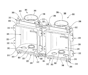
With reference to FIG. 1, an example assembly 300 of plumbing outlet boxes is
shown. The plumbing outlet boxes 305 may comprise a housing 310 that includes
a top
wall 320, a bottom wall 325, a first side wall 330, and a second side wall
335. The
housing 310 may define an opening 340 that provides access to an interior 345
of the
housing. In some embodiments, either or both of the top wall 320 and bottom
wall 325
may include one or more connectors 312. Additionally or alternatively, some
embodiments of the plumbing outlet box 305 may further include one or more
mounting
tabs 352 for engaging the wall and/or stud to hold the box in position. In
some
embodiments, as shown in FIG. 1, the mounting tabs 352 may include one or more
holes
for inserting a fastener (e.g., a screw, bolt, nail, clip, or the like) to
attach the plumbing
outlet box 305 to a stud or wall. In other embodiments, as detailed below, the
mounting
tabs may be configured to engage another plumbing outlet box.
With continued reference to FIG. 1, the plumbing outlet box assembly 300 may
be
held together, at least in part, by one or more brackets 322. As detailed
below, the
brackets may be configured to engage the at least one connector 312 of each
plumbing
outlet box 305 in the assembly 300. The brackets 322 may span the plumbing
outlet
boxes 305 to hold the boxes in a predetermined orientation. In some
embodiments, as
- 6 -
CA 02892865 2015-05-22
_
-
shown in FIG. 1, there may be at least two brackets 322 connecting the
plumbing outlet
boxes 305. In some alternative embodiments, as detailed below, a single
bracket may
connect the two boxes. In some further embodiments, the brackets 322 may be
shorter
than the width of the plumbing outlet boxes, such that they engage at least
one connector
312.
As detailed below, the brackets 322 and/or the connectors 312 may include one
or
more projections that hold the brackets in position relative to the plumbing
outlet boxes
305. Additionally or alternatively, fasteners (e.g., screws, bolts, nails,
clips, or the like)
may be used to hold the brackets 322 and boxes 305 together. In some further
embodiments, no fasteners may be used and each of the brackets 322 and
plumbing
outlet boxes 305 may be independently secured to a wall and/or stud, such that
the
brackets provide rigidity to the structure of the plumbing outlet box assembly
300 while
slidably engaging the boxes. In some embodiments, each bracket 322 may engage
at
least one connector 312 of a plumbing outlet box 305. In some further
embodiments,
each bracket 322 may engage at least two connectors 312 of a plumbing outlet
box 305
to provide further rigidity. In some embodiments, brackets 322 may engage one
or more
connectors 312 on the same side of the respective plumbing outlet boxes 305.
For
example, as shown in FIG. 1, each bracket 322 is connected to the connectors
312 on
either the respective top walls 320 or the bottom walls 325 of each plumbing
outlet box
305. In some alternative embodiments, as detailed below, a bracket may connect
to one
or more connectors on both the top and bottom walls of the plumbing outlet
boxes.
With continued reference to FIG. 1, each plumbing outlet box 305 may include
at
least two connectors 312 on the top wall 320 and/or bottom wall 325. In such
embodiments, the brackets 322 may engage two or more connectors 312 in order
to give
multiple points of contact with each plumbing outlet box. Such a configuration
may
reduce torsion on the bracket 322 and/or connectors 312. In the embodiment
shown in
FIG. 1, each of the top walls 320 and bottom walls 325 of the plumbing outlet
boxes 305
includes two connectors 312, with a first bracket 322 spanning the top walls
of the
plumbing outlet boxes and a second bracket 322 spanning the bottom walls of
the
plumbing outlet boxes.
In some embodiments, a single plumbing outlet box may be fastened within a
wall
using the mounting tabs 352 and/or brackets 322. In some alternative
embodiments,
more than two plumbing outlet boxes may be mounted within a wall using a
single set of
brackets 322. For example, the brackets 322 may extend to a third plumbing
outlet box
and connect the third plumbing outlet box as part of the plumbing outlet box
assembly. In
some embodiments, a bracket may be configured to span multiple studs and
support one
or more plumbing outlet boxes therebetween. In some alternative embodiments, a
- 7 -
CA 02892865 2015-05-22
_
bracket may be configured to attach to a single stud and support one or more
plumbing
outlet boxes on either side of the stud. In yet another embodiment, the
bracket may be
configured to attach directly to the wall surface (e.g., a drywall surface) to
support one or
more plumbing outlet boxes. Additionally or alternatively, angled brackets 398
may be
disposed on one or more of the connectors 312 for allowing a fastener to
further secure
the plumbing outlet box 305 to a stud.
Referring back to FIG. 1, the plumbing outlet boxes 305 may have connectors
312
and/or mounting tabs 352 that are rotationally symmetric. Due to the
rotational symmetry
of the placement of the respective receiving features and mounting tabs, the
plumbing
outlet box housings 310 may be configured to be engaged to each other
regardless of the
relative orientation of the two plumbing outlet box housings. In other words,
in some
embodiments, one or both of the plumbing outlet boxes 305 shown in FIG. 1 may
be
rotated by 180' from the orientation shown (and/or from the orientation of the
other of the
two plumbing outlet boxes) while still maintaining the ability to be attached
to the bracket
and/or wall as described above.
In this regard, in some embodiments, each plumbing outlet box 305 of the
assembly 300 may be substantially identical. For the purposes of the
description herein,
the term "identical" does not preclude the existence of a certain
imperfections and
differences within an acceptable degree of manufacturing tolerance as
understood in the
art. Rather, the configuration of each plumbing outlet box 305 may be such
that the size,
number, position, function, etc. of the connections and openings for making
such
connections are the same.
Accordingly, a single configuration of a plumbing outlet box (such as the
configuration of one of the plumbing outlet boxes 305 shown in Fig. 1, for
example) may
be used as a "universal" plumbing outlet box, with some or all of the
available
connections being used as desired to accommodate the particular installation
scenario
and with the particular orientation of the plumbing outlet box selected to
optimize the use
of the connections. Referring again to Fig. 1, for example, the plumbing
outlet box 305
may be configured such that the top wall 320 and the bottom wall 35 each
includes drain
openings 385, 390. The bottom drain opening 385 may, for example, have a
diameter of
1 inch, whereas the top drain opening 390 may, for example have a diameter of
2 inches.
In other embodiments, however, the drain openings 385, 390 may be the same
size as
each other or different sizes, and the sizes may be larger or smaller than
those described
herein to accommodate different consumer requirements and usage scenarios. In
still
other embodiments, at least one of the top wall and the bottom wall may also
include a
pair of laterally-spaced openings 392, 394 configured to accommodate hot and
cold water
- 8 -
CA 02892865 2015-05-22
supply connections, such as to allow the plumbing outlet box 305 to be used in
a washing
machine installation.
Turning to FIG. 2, a partial view of a plumbing outlet box 305 is shown having
a
connector 312 disposed on a top wall 320 thereof. In some embodiments, the
connector
may be offset from the front edge 366 of the plumbing outlet box 305 by
approximately
the width of a sheet of drywall, or other wall-forming material. In such
embodiments, the
offset may allow the front edge 366 of the plumbing outlet box 305 to rest
flush with the
surface of the wall when installed.
In some embodiments, the connectors 312 may be defined as a series of offset
tabs 315 configured to define a channel 316 therebetween. The channel 316 may
be
configured to receive an engaging portion of a bracket 322 (shown in FIG. 1)
therein. For
example, in the embodiment of FIG. 2, the channel 316 is defined by three
vertically
oriented, offset tabs 315 connected to the top wall 320 at one end and to a
bar 317 at a
distal end. The offset tabs 315 may be offset front-to-back (e.g., on an axis
connecting
the front edge 366 with a back surface) such that the bracket 322 is
configured to be
disposed therebetween. In some further embodiments, the offset tabs 315 may be
offset
in a side-to-side direction (e.g., along an axis connecting the first side
wall 330 with the
second side wall 335 shown in FIG. 1). In some embodiments, the width (e.g.,
from front
to back) of the channel 316 may be narrower than a width of the bracket 322
such that
the bracket must curve slightly to engage the connector 312. In such
embodiments, the
plumbing outlet box 305 may be attached to the bracket 322 via friction.
In some embodiments, the connectors 312 and/or the brackets 322 may include
engaging portions defining projections that engage one another to prevent
longitudinal
motion through the channel 316 once the bracket is engaged with the connector.
As
detailed below, the projections may be one-way projections that deflect
inwardly when a
bracket 322 is inserted into the connector 312 but may deflect outwardly and
prevent the
bracket from being pulled back through the connectors. The projections may
engage one
or more of the connectors 312. For example, in some embodiments, a projection
may
only engage one connector 312 with a second connector 312 engaging the bracket
via
the constraints of the channel 316 only. In some alternative embodiments, the
connectors may include buckles, clips, fasteners, or receiving mechanisms
therefor that
enable a bracket to be engaged with a plumbing outlet box.
Turning to FIG. 3, a bracket 322 is shown in accordance with some embodiments
of the present invention. In some embodiments, the bracket may be a
substantially flat
piece of material configured to engage the connectors 312 (shown in FIGS. 1-
2). In some
embodiments, the bracket may be made of a rigid material, such as metal or
plastic, and
may be configured to at least partially support one or more of the plumbing
outlet boxes.
- 9 -
CA 02892865 2015-05-22
With reference to FIG. 1, in some embodiments, the bracket 322 is configured
to be
oriented with its larger width oriented vertically (e.g., in the configuration
shown in FIG. 1)
such that a longitudinal dimension of the bracket 322 may span the plumbing
outlet boxes
305 and the larger width supports at least part of the weight of the boxes. In
such
embodiments, the bracket 322 may flex less in the plane of its larger width
than in a plane
of its smaller width (e.g., less vertical flex than front-to-back flex in the
orientation of FIG.
1), such that the larger width may support the weight of the boxes. In some
embodiments, the bracket may have at least one fold along its longitudinal
axis to
increase the rigidity of the bracket. In some other embodiments, the bracket
may be
substantially cylindrical, square, or another shape. In such embodiments, the
connectors
(e.g., the connectors 312 shown in FIG. 2) may be a corresponding shape to
receive the
brackets.
In some embodiments, the bracket 322 may support the one or more plumbing
outlet boxes via tension in the longitudinal direction. In such embodiments,
the bracket
322 may fixedly engage one or more connectors (e.g., the connectors 312 shown
in FIG.
2) and apply a tension to the connector towards a stud (e.g., towards the
center of the
assembly 300 in FIG. 1). At least a portion of the weight of the one or more
plumbing
outlet boxes may then be supported by friction with the stud. For example, in
the
embodiment shown in FIG. 1, the brackets 322 may apply a tension on each of
the
plumbing outlet boxes 305 towards one another to press each box against a stud
therebetween.
With continued reference to FIG. 3, the bracket 322 may include one or more
fastening features 332 for engaging a wall and/or stud to position the one or
more
plumbing outlet boxes. The fastening features 332 may be built into the
bracket 322, as
shown in FIG. 3, or may alternatively be separate fastening features
configured to engage
the bracket and a wall and/or stud. Built in fastening features 332 may be
formed from
the bracket itself. For example, with reference to FIG. 3, the fastening
feature may be a
pointed fastening feature 336 that may be formed by cutting the pointed
fastening feature
from a section of the bracket. In some embodiments, the pointed fastening
feature 336
may remain attached to the bracket 322 on at least one side, and may be
separated from
the bracket on the remaining sides to form a cutout 338. In such embodiments,
the
bracket may be attached to a wall or stud by pressing (e.g., with a hammer)
the pointed
fastening feature 336 into the wall or stud structure. In some alternative
embodiments,
the built in fastening feature may be a projection, spike, screw, or the like
that may be
attached or integrally formed with the bracket 322. In some embodiments, a
plurality of
built in or separate fastening features may be used. Some embodiments may
include at
- 10-
CA 02892865 2015-05-22
. .
least two fastening features facing opposite directions to simultaneously
engage a wall
and a stud.
As noted above, some embodiments of the bracket 322 may include one or more
projections (e.g., the projections 450 shown in FIG. 5) for engaging one or
more
connectors (e.g., the connectors 312 shown in FIG. 2). The projections may be
spaced in
a predetermined orientation on the bracket 322 to fixedly engage one or more
connectors. For example, referring back to FIG. 1, in some embodiments, the
bracket
322 may be configured to fixedly engage at least one connector 312 on each
plumbing
outlet box 305. In some embodiments, the bracket 322 may fixedly engage the
outermost
(e.g., farthest from the center of the assembly 300) connectors 312 and
slidingly engage
the innermost (e.g., closest to the center of the assembly) connectors. In
some
alternative embodiments, the bracket 322 may fixedly engage the innermost
connectors
312 and may slidingly engage the outermost connectors. Moreover, any other
combination of fixed and sliding engagement between the brackets and the
connectors
may be used. In some embodiments, a fastener (e.g., screw, bolt, nail, clip,
or the like)
may engage one or more connectors 312 with the bracket 322 via receiving
openings 334
in the bracket. The openings 334 may be positioned to fixedly engage the
connectors as
detailed above. In some embodiments, any number of openings 334 may be
provided to
receive fasteners to engage the connectors 312, a stud, and/or wall. In some
further
embodiments, evenly spaced openings 334 may be provided along the bracket 322
to
allow the bracket to flexibly engage the plumbing outlet boxes, wall, and/or
studs.
Turning to FIG. 4, a perspective view of an embodiment of a plumbing outlet
box
assembly 400 is shown having an I-shaped bracket 422. The plumbing outlet box
assembly 400 may include substantially the same plumbing outlet boxes 305 as
detailed
above with respect to FIG. 1. In some further embodiments, as described below,
various
embodiments of the plumbing outlet boxes may be used with the one or more
brackets
detailed herein.
In the embodiment shown in FIG. 4, the bracket 422 engages the plumbing outlet
boxes 305 via the connectors 312 to maintain the plumbing outlet box assembly
400 in a
predetermined configuration and mount the assembly within a wall. The I-shaped
bracket
422 may span vertically from the top wall 320 to the bottom wall 325 of either
or both
plumbing outlet boxes in order to engage at least one connector 312 on either
side of the
assembly 400.
In some embodiments, the bracket 422 may engage at least two connectors 312
on each plumbing outlet box 305. In such embodiments, the two connectors 312
may
include at least one connector on the top wall 320 and at least one connector
on the
bottom wall 325 of a plumbing outlet box 305. In some further embodiments, the
bracket
-11-
CA 02892865 2015-05-22
422 may engage at least two connectors 312 on the top wall 320 and/or at least
two
connectors on the bottom wall 325. In some embodiments, the bracket 422 may
engage
less than all of the connectors on a given wall (e.g., the top walls 320 or
bottom walls 325
shown in FIG. 4). In such embodiments, the connectors 312 may still be
disposed on
their respective walls to maintain the rotational symmetry of the plumbing
outlet box 305,
as discussed above. Additionally or alternatively, a second I-shaped bracket
422 may be
connected to a plumbing outlet box 305 proximate an opposite side wall, such
that a third
plumbing outlet box may be connected to the assembly 400.
The bracket 422 may engage the connectors 312 using one or more projections
on either or both of the connector and the bracket as detailed above (e.g.,
with respect to
the bracket 322 shown in FIG. 3). In some embodiments, the projections may
engage the
side surfaces of the connectors (e.g., the side surfaces 318 shown in FIG. 3).
Turning to FIG. 5, an I-shaped bracket 422 is shown in accordance with some
embodiments of the present invention. As detailed above, the bracket 422 may
engage
one or more plumbing outlet boxes in a similar manner to other brackets (e.g.,
the bracket
322 shown in FIG .3) described herein. The bracket 422 may include one or more
engaging portions 440 at a top end 424 and a bottom end 426 configured to
engage the
connectors (e.g., the connectors 312 shown in FIG. 4).
The top end 424 and the bottom end 426 of the bracket 422 may be connected by
a middle portion 442. In some embodiments, the middle portion 442 of the
bracket 422
may be approximately the width of a stud at its widest point. With reference
to FIG. 4, the
middle portion of the bracket 422 may extend between the side walls 330, 335
of the
plumbing outlet boxes 305.
Referring to FIGS. 4-5, in some embodiments, the middle portion 442 may
include
one or more recesses 454 for receiving the mounting tabs (e.g., the mounting
tabs 352
shown in FIG. 4). In such embodiments, the mounting tabs 352 may directly abut
the
stud, and in some embodiments, the mounting tabs 352 and bracket 422 may be
substantially coplanar. In some other embodiments, the bracket 422 may not
include
recesses 454 and/or the plumbing outlet boxes 305 may either not include
mounting tabs
352 or the mounting tabs may overlap the bracket 422 such that one of the
bracket or the
mounting tabs may directly abut the stud while the other may abut the wall.
Similar to the linear bracket 322 detailed above, the I-shaped bracket 422 may
include one or more receiving openings 452 for receiving a fastening device
and/or one or
more fastening features 432. As detailed above, the one or more fastening
features 432
may be configured to engage a wall and/or stud to position the one or more
plumbing
outlet boxes. The fastening features 432 may be built into the bracket 422, as
shown in
FIG. 5, or may separately engage the bracket 422 and a wall and/or stud. Built
in
- 12-
CA 02892865 2015-05-22
fastening features 432 may be formed from the bracket itself. For example,
with
reference to FIG. 3, the fastening feature may be a pointed fastening feature
436 that
may be formed by cutting the pointed fastening feature from a section of the
bracket. In
some embodiments, the pointed fastening feature 436 may remain attached to the
bracket 422 on at least one side, and may be separated from the bracket on the
remaining sides to form a cutout 438. In such embodiments, the bracket may be
attached
to a wall or stud by pressing (e.g., with a hammer) the pointed fastening
feature 436 into
the wall or stud structure. In some alternative embodiments, the built in
fastening feature
may be a projection, spike, screw, or the like that may be attached or
integrally formed
with the bracket 422. In some embodiments, a plurality of built in or separate
fastening
features may be used. Some embodiments may include at least two fastening
features
facing opposite directions to simultaneously engage a wall and a stud. In some
embodiments, the bracket 422 may include receiving openings 452 for receiving
fastening
devices therethrough. The fastening devices (not shown) may connect the
bracket 422 to
the stud, wall, and/or plumbing outlet boxes.
In some embodiments, the mounting tabs 352 may include mounting openings
354 for receiving a fastener therein. In some embodiments, the bracket 422 may
have a
corresponding opening for receiving a fastener when the mounting tab 352 and
the
bracket overlap. In some embodiments, as discussed in greater detail below,
the
mounting tabs may directly engage a receiving feature of another plumbing
outlet box. In
such embodiments, a fastener may simultaneously engage the bracket 422, the
mounting
tab and the receiving feature.
As detailed above, the bracket 422 may engage one or more points of contact
(e.g., the connectors 312) on the plumbing outlet box 305. In some embodiment,
the
bracket 422 may engage at least two points of contact on each plumbing outlet
box 305.
For example, with reference to FIG. 4, the engaging portions 440 of the
bracket 422 may
engage the connectors 312 on the top wall 320 and/or bottom wall 325 of each
plumbing
outlet box 305. In some embodiments, any combination of connection points may
be
used to engage the bracket 422 with a plumbing outlet box 305. For example, a
bracket
may engage one connector 312 on each of the top 320 and bottom 325 walls as
shown in
FIG. 4. In some other embodiments, the bracket 422 may engage one of the
connectors
on either the top 320 or bottom 325 wall. The engaging portions 440 of the
bracket may
define a length that reaches only one of the connectors 312, or in yet some
other
embodiments, the engaging portions 440 may span the width of the plumbing
outlet box
305 and may engage each of the connectors 312.
The bracket 422 may also be configured to connect the plumbing outlet box
assembly 400 in any of a number of configurations. For example, each plumbing
outlet
- 13-
CA 02892865 2015-05-22
box 305 may be connected at a connector 312 on the top 320 and bottom 325
surfaces
as shown in FIG. 4. In some alternative embodiments, the bracket 422 may be
linearly or
diagonally connected to only one connector 312 on each plumbing outlet box. In
some
further embodiments multiple connectors 312 on one or more of the walls of the
plumbing
outlet boxes may be used.
The engaging portions 440 of the bracket 422 may be configured to engage the
plumbing outlet boxes 305 via projections or receiving openings that engage
the
connectors. For example, with reference to FIG. 5, the engaging portion 440
may include
a projection 450 that forms a lip along the surface of the bracket 422. The
projection 450
may be configured to engage a side surface of the connectors (e.g., the side
surface 318
of the connector 312 shown in FIG. 2). In some alternative embodiments, the
projections
may be disposed on the connectors 312 and may be received by openings in the
bracket.
As detailed above with respect to the linear bracket 322, the bracket 422 may
be
inserted into a channel 316 defined by the connector 312 in order to engage
the plumbing
outlet box 305. Also as detailed above, the bracket and connectors may take
any shape
that enables the bracket to be slidingly or fixedly engaged with the plumbing
outlet box.
In the configurations detailed above, the bracket may fixedly engage a subset
of the
connectors and slidingly engage the remaining connectors. For example, when
multiple
connectors on a single wall are engaged, only one or both may be fixedly
engaged with
the bracket. Alternatively, only one or multiple connectors on a plumbing
outlet box may
be fixedly engaged with the bracket, with the remaining connectors being
slidingly
engaged.
In the embodiment shown in FIG. 5, the bracket 422 includes projections 450
that
stand out from the surface of the bracket to engage an edge of the connector
(e.g., the
edge or side surface 318 shown in FIG. 2). The projection 450 may be formed as
a bump
or protrusion from the surface of the bracket 450 or alternatively may be
formed as an
angled ramp for directionally engaging the connector. For example, in the
embodiment
shown in FIG. 5, the projection 450 forms a raised lip that may deflect
inwardly as the
bracket 422 is inserted into the channel (e.g., the channel 316 shown in FIG.
2). In such
an embodiment, each projection 450 may restrict movement of the bracket
relative to the
plumbing outlet box 305 in a single direction. In some embodiments the
structure of the
bracket (e.g., the middle portion 442) may contact the plumbing outlet box 305
to restrict
the other direction. In some embodiments the projection 450 may be formed by
linearly
cutting partially through the vertical length of the engaging portion 440 and
folding the
projection 450 out of the plane of the bracket 422. In some other embodiments,
the
projection may be formed in any direction to engage a desired surface of the
plumbing
outlet box. In yet some further embodiments, multiple cuts in the bracket may
form a
- 14-
CA 02892865 2016-09-09
complex projection. In some embodiments, the bracket may be cut in the center
of the
bracket 422 to form a raised projection that is vertically proximate the
center of the
engaging portion 440. Alternatively, as detailed above, the bracket 422 may
include a
receiving opening or edge for engaging a similar projection on the plumbing
outlet box.
As detailed above with respect to the linear bracket 322, the projection may
be any type
of bump, buckle, clip, clamp, raised portion, or other engaging feature, or a
corresponding
receiving surface therefore, that may enable the bracket to engage a plumbing
outlet box.
In the embodiments detailed herein, the brackets 322, 422 may be used to
connect any number plumbing outlet boxes to a wall, stud, or studs. For
example, the
brackets 322, 422, either alone or in combination with the mounting tabs
(e.g., the
mounting tabs 352 shown in FIG. 1) may fasten to a stud and/or wall as
detailed herein.
The brackets 322, 422 may retain the plumbing outlet box with or without an
additional
plumbing outlet box connected to an opposite side of the bracket. In some
further
embodiments, additional brackets 322, 422 or longer versions of a single
bracket may be
configured to connect three or more plumbing outlet boxes into a single
assembly. In
some embodiments the brackets 322, 422 may span two or more studs to support
one or
more plumbing outlet boxes therebetween.
Additional reference will be made to several embodiments of the plumbing
outlet
boxes that are also described in U.S. Patent No. 9,394,674, entitled "Plumbing
Outlet Box
with Integrated Mounting Features" and filed November 7, 2014, and U.S. Patent
No.
9,388,555, entitled "Plumbing Outlet Box With Integrated Mounting Features"
and filed
January 14, 2014. In each of the embodiments of plumbing outlet boxes
discussed
herein, any of the brackets 322, 422 may be used alone or in combination with
other
brackets and features to attach one or more plumbing outlet boxes to a wall or
one or
more studs within a wall.
Turning to FIG. 6, an embodiment of a plumbing outlet box 5 is shown that is
configured to be mounted within a wall (not shown). The plumbing outlet box 5
may
comprise a housing 10 that includes a top wall 20, a bottom wall 25, a first
side wall 30,
and a second side wall 35. The housing 10 may define an opening 40 that
provides
access to an interior 45 of the housing. The plumbing outlet box 5 may be
configured to
receive one or more brackets 322, 422 as detailed above.
With continued reference to FIG. 6, the plumbing outlet box 5 may further
include
a first receiving feature 50 extending outwardly from the first side wall 30
and a second
receiving feature 55 extending outwardly from the second side wall 35.
Similarly, a first
mounting tab 60 may extend outwardly from the first side wall 30, and a second
mounting
tab 65 may extend outwardly from the second side wall 35. The receiving
features 50, 55
-15-
CA 02892865 2015-05-22
and the mounting tabs 60, 65 may be integral with the housing (e.g.,
integrally molded
from the same plastic material, such as polyvinyl chloride (PVC)) in some
cases.
Receiving features 50, 55 of one plumbing outlet box may be configured to
receive and engage with mounting tabs 60, 65 of another plumbing outlet box,
such that
two plumbing outlet boxes may be attached to each other in a side-by-side
manner (e.g.,
as shown in FIG. 7 and described in greater detail below) by connecting a
receiving
feature and a mounting tab extending from one side of one of the plumbing
outlet boxes
with a corresponding mounting tab and receiving feature extending from a
corresponding
side of the other plumbing outlet box.
As such, each receiving feature 50, 55 (shown in FIG. 6) may be configured to
receive a mounting tab of another plumbing outlet box (e.g., where the
mounting tab of
the other plumbing outlet box is configured as shown and described herein with
respect to
the first and second mounting tabs 60, 65). Likewise each mounting tab 60, 65
may be
configured to be received by a receiving feature of another plumbing outlet
box (e.g.,
where the receiving feature of the other plumbing outlet box is configured as
shown and
described herein with respect to the first and second receiving features 50,
55). The
engagement of receiving features with mounting tabs is described in greater
detail below.
For ease of explanation, the mounting tabs and receiving features of the other
plumbing
outlet boxes are referenced herein as "engaging" mounting tabs and "engaging"
receiving
features.
As illustrated in FIG. 6, the first receiving feature 50 may be located
proximate the
top wall 20 and the second receiving feature 55 may be located proximate the
bottom wall
25, while the first mounting tab 60 may be located proximate the bottom wall
25 and the
second mounting tab 65 may be located proximate the top wall 20. Said
differently, the
first and second receiving features 50, 55 may be disposed near one pair of
opposite
corners of the plumbing outlet box 5 with respect to each other. Likewise, the
first and
second mounting tabs 60, 65 may be disposed near the other pair of opposite
corners of
the plumbing outlet box 5 with respect to each other. Similar to the
embodiments detailed
above, the plumbing outlet box 5 may further include a connector 312 for
engaging a
bracket (e.g., the brackets 322 or 422 detailed above).
Thus, considering only the placement of the receiving features 50, 55 and the
mounting tabs 60, 65 about the perimeter of the opening 40, the receiving
features and
mounting tabs are placed so as to impart rotational symmetry to the plumbing
outlet box
5, as detailed above. As a result of this rotational symmetry (e.g., 2-fold
rotational
symmetry as shown), a rotation of 180 of the view shown in FIG. 6 results in
the same
relative position of the receiving features and mounting tabs. Thus, as
described in
greater detail herein, an assembly of outlet boxes may be placed in side-by-
side fashion
- 16-
CA 02892865 2015-05-22
and engaged via engagement of the corresponding receiving features 50, 55 and
mounting tabs 60, 65, regardless of whether the top wall 20 of the housing is
facing up
(as shown in FIG. 6) or facing down (e.g., rotated 1800 from the view shown in
FIG. 6).
Turning now to FIG. 7, embodiments of the plumbing outlet box 5 (e.g., shown
in
FIG. 6) as described above may be attached to each other via corresponding
receiving
features 50, 55 and mounting tabs 60, 65 to form an assembly 80 of plumbing
outlet
boxes 5, 5'. In this regard, the assembly 80 may include at least a first
plumbing outlet
box 5 and a second plumbing outlet box 5', each configured for mounting within
a wall,
and each configured as described above with respect to FIG. 6. Each plumbing
outlet
box 5, 5' may thus comprise a housing including a top wall, a bottom wall,
first and
second side walls, and an opening providing access into an interior of the
housing. A first
receiving feature may extend outwardly from the first side wall; a second
receiving feature
may extend outwardly from the second side wall; a first mounting tab may
extend
outwardly from the first side wall; and a second mounting tab may extend
outwardly from
the second side wall. As described above with respect to FIG. 6, the first
receiving
feature may be located proximate the top wall and the second receiving feature
may be
located proximate the bottom wall. Similarly, the first mounting tab may be
located
proximate the bottom wall and the second mounting tab may be located proximate
the top
wall.
With reference to FIG. 7, the housing 10' of the second plumbing outlet box 5'
may be configured to be engaged with the housing 10 of the first plumbing
outlet box 5
via engagement of one of the first or second mounting tabs 60', 65' of the
second
plumbing outlet box housing 10' with a corresponding one of the first or
second receiving
features 50, 55 of the first plumbing outlet box housing 10 and engagement of
one of the
first or second receiving features 50', 55' of the second plumbing outlet box
housing 10'
with a corresponding one of the first or second mounting tabs 60, 65 of the
first plumbing
outlet box housing 10. In the example illustrated in FIG. 7, for example, the
first receiving
feature 50 of the first plumbing outlet box housing 10 is engaged with the
second
mounting tab 65' of the second plumbing outlet box housing 10', and the first
mounting
tab 60 of the first plumbing outlet box housing 10 is engaged with the second
receiving
feature 55' of the second plumbing outlet box housing 10'. Moreover, due to
the
rotational symmetry of the placement of the respective receiving features and
mounting
tabs, the first and second plumbing outlet box housings 10, 10' may be
configured to be
engaged to each other regardless of the relative orientation of the two
plumbing outlet
box housings. In other words, in some embodiments, one or both of the plumbing
outlet
boxes 5, 5' shown in FIG. 7 may be rotated by 180 from the orientation shown
(and/or
-17-
CA 02892865 2015-05-22
from the orientation of the other of the two plumbing outlet boxes) while
still maintaining
the ability to be attached to each other as described above.
In this regard, in some cases, the first and second plumbing outlet box
housings
10, 10' may be identical (e.g., have identical configurations). For the
purposes of the
description herein, the term "identical" does not preclude the existence of a
certain
imperfections and differences within an acceptable degree of manufacturing
tolerance as
understood in the art. Rather, the configuration of each plumbing outlet box
5, 5' may be
such that the size, number, position, function, etc. of the connections and
openings for
making such connections are the same.
Accordingly, a single configuration of a plumbing outlet box (such as the
configuration of the plumbing outlet box 5 shown in FIG. 6, for example) may
be used as
a "universal" plumbing outlet box, with some or all of the available
connections being
used as desired to accommodate the particular installation scenario and with
the
particular orientation of the plumbing outlet box selected to optimize the use
of the
connections. Referring again to FIG. 6, for example, the plumbing outlet box 5
may be
configured such that the top wall 20 and the bottom wall 25 each includes
drain openings
85, 90. The top drain opening 85 may, for example, have a diameter of 1 1/2
inches,
whereas the bottom drain opening 90 may, for example have a diameter of 2
inches. In
other embodiments, however, the drain openings 85, 90 may be the same size as
each
other or different sizes, and the sizes may be larger or smaller than those
described
herein to accommodate different consumer requirements and usage scenarios. In
still
other embodiments, at least one of the top wall and the bottom wall may also
include a
pair of laterally-spaced openings 92, 94 configured to accommodate hot and
cold water
supply connections, such as to allow the plumbing outlet box 5 to be used in a
washing
machine installation.
As noted above, due to the rotational symmetry of the placement of the
receiving
features and mounting tabs, the plumbing outlet box 5 may be orientated as
shown in
FIG.6 or in an orientation that is rotated by 180 from the orientation shown
in FIG. 6. In
some embodiments, the two laterally-spaced openings 92, 94 may be used to
accommodate hot and cold water supply connections, and the drain opening 90
may be
used to receive effluent (e.g., from a washing machine).
Accordingly, as described above, a method of installing a plumbing outlet box
assembly comprising at least two plumbing outlet boxes within a wall is
described that
includes providing first and second plumbing outlet boxes. Each plumbing
outlet box may
have a housing that includes a top wall, a bottom wall, first and second side
walls, and an
opening providing access into an interior of the housing. As described above
with respect
to the figures, a first receiving feature may extend outwardly from the first
side wall; a
-18-
CA 02892865 2015-05-22
second receiving feature may extend outwardly from the second side wall; a
first
mounting tab may extend outwardly from the first side wall; and a second
mounting tab
may extend outwardly from the second side wall. The first receiving feature
may be
located proximate the top wall and the second receiving feature may be located
proximate the bottom wall. Likewise, the first mounting tab may be located
proximate the
bottom wall, and the second mounting tab may be located proximate the top
wall.
In some embodiments, the second plumbing outlet box housing may be engaged
to the first plumbing outlet box housing via engagement of one of the first or
second
mounting tabs of the second plumbing outlet box housing with a corresponding
one of the
first or second receiving features of the first plumbing outlet box housing
and engagement
of one of the first or second receiving features of the second plumbing outlet
box housing
with a corresponding one of the first or second mounting tabs of the first
plumbing outlet
box housing. Additionally or alternatively, as detailed herein, the first and
second
plumbing outlet boxes may be connected via one or more brackets. The first
plumbing
outlet box housing may be fastened within the cutout, as described above, and
the
second plumbing outlet box housing may also be fastened within the cutout.
Moreover, the first plumbing outlet box and the second plumbing outlet box may
be fastened within the cutout by inserting a fastener through an opening on
the respective
receiving feature, as described above. For example, each receiving feature of
the first
and second plumbing outlet boxes may comprise a pair of lateral receiving arms
and a
main receiving arm disposed therebetween. Fastening the first plumbing outlet
box within
the cutout may comprise inserting a fastener through an opening in the
respective lateral
receiving arms of the first plumbing outlet box and inserting a fastener
through an
opening in the main receiving arm of the first plumbing outlet box following
engagement
of the second plumbing outlet box housing to the first plumbing outlet box
housing.
Fastening the second plumbing outlet box within the cutout may comprise
inserting a
fastener through a slot in the mounting tab of the second plumbing outlet box
and the
opening in the corresponding main receiving arm of the first plumbing outlet
box following
engagement of the second plumbing outlet box housing to the first plumbing
outlet box
housing. In other embodiments, however, at least some of the fasteners may be
applied
to the first plumbing outlet box prior to engaging the second plumbing outlet
box housing
to the first plumbing outlet box housing.
FIG. 8 shows an embodiment of the present invention having an alternative
embodiment of at least the mounting tabs and receiving features. In the
embodiment
shown in FIG. 8, a plumbing outlet box 105 is shown that is configured to be
mounted
within a wall (not shown). The plumbing outlet box 105 may comprise a housing
110
including a top wall 120, bottom wall 125, first side wall 130, and second
side wall 135.
-19-
CA 02892865 2015-05-22
The housing 110 may define an opening 140 that provides access to an interior
145 of
the housing. Similar to the embodiments detailed above, the plumbing outlet
box 105
may further include a connector 312 for engaging a bracket (e.g., the brackets
322 or 422
detailed above).
With continued reference to FIG. 8, the plumbing outlet box 105 may include a
first receiving feature 150 disposed on the first side wall 130 and a second
receiving
feature 155 disposed on the second side wall 135. Similarly, a first mounting
tab 160
may extend outwardly from the first side wall 130, and a second mounting tab
165 may
extend outwardly from the second side wall 135. The receiving features 150,
155 and the
mounting tabs 160, 165 may be integral with the housing (e.g., integrally
molded from the
same plastic material, such as polyvinyl chloride (PVC)) in some cases, as
described
herein.
Receiving features 150, 155 of one plumbing outlet box may be configured to
receive and engage with mounting tabs of another plumbing outlet box, such
that two
plumbing outlet boxes may be attached to each other in a side-by-side manner
(e.g., as
shown in FIG. 9 and described in greater detail herein) by connecting a
receiving feature
and a mounting tab extending from one side of one of the plumbing outlet boxes
with a
corresponding mounting tab and receiving feature extending from a
corresponding side of
the other plumbing outlet box.
Accordingly, each receiving feature 150, 155 may be configured to receive a
mounting tab of another plumbing outlet box (e.g., where the mounting tab of
the other
plumbing outlet box is configured as shown and described herein with respect
to the first
and second mounting tabs 160, 165). Likewise each mounting tab 160, 165 may be
configured to be received by a receiving feature of another plumbing outlet
box (e.g.,
where the receiving feature of the other plumbing outlet box is configured as
shown and
described herein with respect to the first and second receiving features 150,
155). The
engagement of receiving features with mounting tabs is described in greater
detail herein.
As noted above, for ease of explanation, the mounting tabs and receiving
features of the
other plumbing outlet boxes are referenced herein as "engaging" mounting tabs
and
"engaging" receiving features. These "engaging" features may include
substantially the
same structure as their counterparts described herein.
As illustrated in FIG. 8, the first receiving feature 150 may be located
proximate
the bottom wall 125 and the second receiving feature 155 may be located
proximate the
top wall 120, while the first mounting tab 160 may be located proximate the
top wall 120
and the second mounting tab 165 may be located proximate the bottom wall 125.
Said
differently, the first and second receiving features 150, 155 may be disposed
near one
pair of opposite corners of the plumbing outlet box 105 with respect to each
other.
- 20 -
CA 02892865 2015-05-22
Likewise, the first and second mounting tabs 160, 165 may be disposed near the
other
pair of opposite corners of the plumbing outlet box 105 with respect to each
other.
Turning now to FIG. 9, as with the embodiments described with respect to FIG.
6,
some embodiments of the plumbing outlet box 105 (e.g., shown in FIG. 8) as
described
above may be attached to each other via corresponding receiving features 150,
155 and
mounting tabs 160, 165 to form an assembly 180 of plumbing outlet boxes 105,
105'. In
this regard, the assembly 180 may include at least a first plumbing outlet box
105 and a
second plumbing outlet box 105', each configured for mounting within a wall,
and each
configured as described above with respect to FIG. 8. Each plumbing outlet box
105,
105' may thus comprise a housing including a top wall, a bottom wall, first
and second
side walls, and an opening providing access into an interior of the housing. A
first
receiving feature may be disposed on the first side wall; a second receiving
feature may
be disposed on the second side wall; a first mounting tab may extend outwardly
from the
first side wall; and a second mounting tab may extend outwardly from the
second side
wall. As described above with respect to FIG. 8, the first receiving feature
may be located
proximate the bottom wall and the second receiving feature may be located
proximate the
top wall. Similarly, the first mounting tab may be located proximate the top
wall and the
second mounting tab may be located proximate the bottom wall.
With reference to FIG. 9, the housing 110' of the second plumbing outlet box
105'
may engage the housing 110 of the first plumbing outlet box 105 via engagement
of one
of the first or second mounting tabs 160', 165' of the second plumbing outlet
box housing
110' with a corresponding one of the first or second receiving features 150,
155 of the first
plumbing outlet box housing 110 and engagement of one of the first or second
receiving
features 150', 155' of the second plumbing outlet box housing 110' with a
corresponding
one of the first or second mounting tabs 160, 165 of the first plumbing outlet
box housing
110. In the example embodiment of FIG. 9, for example, the first receiving
feature 150 of
the first plumbing outlet box housing 110 may be engaged with the second
mounting tab
165' of the second plumbing outlet box housing 110', and the first mounting
tab 160 of the
first plumbing outlet box housing 110 may be engaged with the second receiving
feature
155' (not shown) of the second plumbing outlet box housing 110'. Moreover, due
to the
rotational symmetry of the placement of the respective receiving features and
mounting
tabs, the first and second plumbing outlet box housings 110, 110' may be
configured to
be engaged to each other regardless of the relative orientation of the two
plumbing outlet
box housings. In other words, in some embodiments, one or both of the plumbing
outlet
boxes 105, 105' shown in FIG. 9 may be rotated by 180 from the orientation
shown
(and/or from the orientation of the other of the two plumbing outlet boxes)
while still
maintaining the ability to be attached to each other as described above.
- 21 -
CA 02892865 2015-05-22
In this regard, in some cases, the first and second plumbing outlet box
housings
110, 110' may be identical (e.g., have identical configurations). For the
purposes of the
description herein, the term "identical" does not preclude the existence of a
certain
imperfections and differences within an acceptable degree of manufacturing
tolerance as
understood in the art. Rather, the configuration of each plumbing outlet box
105, 105'
may be such that the size, number, position, function, etc. of the connections
and
openings for making such connections are the same.
In addition, many other modifications and other embodiments of the invention
will
come to mind to one skilled in the art to which this invention pertains having
the benefit of
the teachings presented in the foregoing descriptions and the associated
drawings.
Therefore, it is to be understood that the invention is not to be limited to
the specific
embodiments disclosed and that modifications and other embodiments are
intended to be
included within the scope of the appended claims. By way of example, any
features of
any embodiment described herein may be wholly or partially incorporated or
combined
into various other embodiments. Although specific terms are employed herein,
they are
used in a generic and descriptive sense only and not for purposes of
limitation.
Moreover, steps in the methods described above may occur in any order and are
not
limited to the order described above.
- 22 -