Note: Descriptions are shown in the official language in which they were submitted.
CA 02892957 2015-05-28
WO 2013/003907
PCT/AU2012/000809
- 1 -
IMPROVED KEY HOLDER
TECHNICAL WIELD
[0001] The present invention relates to personal convenience
devices and, more particularly, to key and small personal item
management systems.
BACKGROUND
[0002] Probably from the time of the invention of the lock and
key, the use of key rings has been the standard and most accepted
simple method of storage and securing of multiple individual
keys.
[0003] Alternative ways of managing the ungainly and pocket-
damaging array of keys provided by the simple key sing by some
form of containment sheathing are known. An example .of a key
sheathing arrangement was disclosed for example in an early
patent, DS1,793.594 by Dodson. At least one disadvantage of the
Dodson arrangement and other attempts is the awkward means of
attaching and detaching keys from the key holder. Such is the
case for example in arrangements in which the keys are still
attached to a key ring and drawn into a restraining flexible
pouch.
[0004] Another disadvantage of known key holders is that they
are limited to just the retention of one or more keys, so that
typically small personal items remain unrestrained in the pocket
of a user.
(0005] It is an object of the present invention to address or
at least ameliorate some of the above disadvantages.
CA 02892957 2015-05-28
WO 2013/003907
PCT/AU2012/000809
- 2 -
Notes
[0006] The term "comprising" (and grammatical variations
thereof) is used in this specification in the inclusive sense of
"having" or "including", and not in the exclusive sense of
"consisting only of".
[0007] The above discussion of the prior art in the Background
of the invention, is not an admission that any information
discussed therein is citable prior art or part of the common
general knowledge of persons skilled in the art in any country.
SUMMARY OF INVENTION
[0008] A key-holder in accordance with one preferred form of the
invention comprises of one or two outer sheathing plates which
sheath the stored keys between them, one or more removable
securing pins or bolts preferably utilising a turn locking
mechanism which secures the stored keys, further preferably one
or more small springs to provide resistance against loose keys
and one or two removable sheath covers for personalisation,
marketing, trademarks, key-set labeling and the like.
[0009] In one form, at least one of the sheathing plates which
may be of plastic, metal or aluminium constructions incorporates
an extruded form and has one or more holes located at each end,
of which at least one hole at a minimum of one end may have a
special form to allow integration and securing with one or two
removable turn locking pins or bolts. This plate may be a flat
extruded section, and may provide a platform for the storing of
one or multiple keys in their most efficient form,. while also
providing the base platform for the attachment of a removable
accessory cover and or accessory attachments.
[0010] In one preferred form, removable accessory covers of
plastic, metal or aluminium construction provide the opportunity
CA 02892957 2015-05-28
WO 2013/003907
PCT/AU2012/000809
- 3 -
for user personalisation, marketing, trademarks, and the like on
the outside visible face by way of their visual design, similar
to mobile phone covers. These removable accessory covers also
provide the potential to house internally within the cover, one
or multiple functional devices or items, examples could be
inclusive of but not limited to; a mirror, an LED torch, alarm
transmitter, USB device, retractable lanyard etc.
[0011] The other sheathing plate of plastic, metal or aluminium
construction, which itself can be a removable accessory cover,
incorporates one or more holes located at each end, of which at
least one hole at a minimum of one end has a diameter to allow
the passing through of a turn locking pin or bolt. This sheathing
plate also has the opportunity to itself incorporate user
personalisation, marketing, trademarks, key-set labeling and the
like on the outside visible face.
[0012] In a preferred form, a removable securing pin or bolt of
plastic, metal or aluminium construction, utilises a turn locking
mechanism and is of a diameter to allow it pass through the hole
at the top of a key(s), and incorporates a form to enable it to
lock into position with at least one sheathing plate. It may also
incorporate a lift upturn assist handle that can be folded down
in a flat position when not in use.
[0013] In a preferred form, the springs may be either round
coiled compression springs or flat creased compression springing
plates, and include a diameter to allow the passing through of a
turn-able locking pin or bolt, and provide a resistance against
the face of the closest aligned key as well as either a sheathing
plate or removal securing pin or bolt head.
[0014] In one form, the removable accessory covers which may be
of plastic, metal or aluminium construction can hide the form
associated with integrating the removable locking pin(s) or.
=
=
CA 02892957 2015-05-28
WO 2013/003907
PCT/AU2012/000809
bolt (s) with the main extruded sheathing plate. These covers may
specifically offer the unprecedented opportunity and product
surface area for user personalisation, marketing, trademarks,
key-set labeling and the like on the outside visible face(s).
[0015] Accordingly, in a first broad for of the invention,
there is provided a key holder for retention of at least one key;
said key holder including at least one accessory compartment;
said at least one accessory compartment formed by attachment of a
selected one of a plurality of interchangeable covers to a
structural element of said key holder.
[0016] Preferably, said key holder includes two said accessory
compartments; each of said accessory compartments formed by
selected said interchangeable covers attached to opposing
structural elements of said key holder.
[0017] Preferably, said interchangeable covers comprise a
generally elongate shell open at its underside; said shell being
of generally arcuate section and rounded at its outer ends.
[0018] Preferably, said interchangeable covers comprise a
generally elongate shell provided at an underside with a closure
for retaining a stored item when said cover is removed from said
structural element of said key holder.
[0019] Preferably, said at least one key is retained between
said structural elements; said structural elements comprising a
base sheathing plate and an opposite retainer sheathing plate;
said base sheathing plate and said retainer sheathing plate
interconnected by locking pins when assembled for use; each said
locking pin operable between a first locked position and a second
unlocked position; said at least one key threaded onto a shaft
portion of a said locking pin.
CA 02892957 2015-05-28
WO 2013/003907
PCT/AU2012/000809
-5 -
[ 0020]
Preferably, said base sheathing plate comprises a
substantially flat elongate plate; said base sheathing plate
provided with apertures proximate opposite ends of said base
sheathing plate; respective said locking pins passing through
said apertures when said key holder is assembled for use.
(0021)
Preferably, said retainer sheathing plate comprises a
substantially flat elongate plate; said retainer sheathing plate
provided with corresponding apertures proximate opposite ends of
said retainer sheathing plate; said corresponding apertures
aligned with said apertures in said base sheathing plate;
respective said locking pins passing through said apertures when
said key holder is assembled for use.
=
(0022]
Preferably, each of said apertures in said retainer
sheathing plate includes engaging elements; said engaging
elements engaging with complementary engaging elements of said
locking pins when said key holder is assembled for use.
[00231
Preferably, an end of a shaft portion of each said
locking pin distal from a head portion is provided with said
complementary engaging elements.
[0024]
Preferably, said head portion is of a larger diameter
than said shaft portion; said head portion provided with a
grasping element; said grasping element operable between an
outwardly projecting position relative said head portion and a
retracted position in which said grasping element lies against
said base sheathing plate.
[0025]
Preferably, spring means disposed between said base
sheathing plate and said retaining sheathing plate limit free
.
movement of said at least one key retained on said shaft portions
CA 02892957 2015-05-28
WO 2013/003907
PCT/AU2012/000809
- 6
of said 'locking pins; said spring means restraining said keys in
their sheathed position.
[0026] Preferably, a removable accessory cover side of said
retainer sheathing plate is provided with retaining structures
along opposing edges of said retainer sheathing plate; said
retaining structures accepting for attachment, complementary
engagement structures of said removable accessory cover.
[00271 Preferably, said interchangeable cover provides a
storage space for storage personal items or functional devices
within a volume of apace provided by said interchangeable cover.
=
[0028] Preferably, exterior surfaces of said interchangeable
cover and said base sheathing plate provide for indicia and
labelling.
[0029] Preferably, said removable accessory cover and said
base sheathing plate are provided with a range of corporate
indicia.
[0030] Preferably, said interchangeable cover and said base
sheathing plate are provided in a range of colours, materials,
finishes and textures.
[0031] Preferably, said locking pins are provided in a range
of lengths to suit a desired key storage capacity.
[0032] Preferably, washers or discs are retained on said
locking pins between said sheathing plates; said discs or washers
replaceable with keys.
[0033] Preferably, small accessory tools of similar size to
keys may be threaded onto said locking pins and retained between
said sheathing plates.
CA 02892957 2015-05-28
WO 2013/003907
PCT/AU2012/000809
- -
,
[00034] In another broad form of the invention, there is
provided a method of customizing a key holder; said method
including the steps of:
(a) providing at least one surface inscribable with indicia,
(b) providing at least one structural element configured for
attachment of interchangeable covers.
[0035] Preferably, said interchangeable covers include a
plurality of selectable covers; each said cover forming a storage
space between an inside surface of said cover and a sheathing
plate of said key holder.
[0036] In another broad form of the invention, there is
provided a method of retaining at least one key in a key holder;
said method including the steps of:
(a) operating a grasping element of at least one locking
pin of said key holder to disengage said locking pin from an
aperture in a retainer sheathing plate of said key holder,
(b) withdrawing said locking pin from said retainer
sheathing plate,
(c) swinging or flexing a base plate of said key holder out
of alignment with said retainer sheathing plate,
(d) passing a shaft portion of said locking pin through an
aperture of said at least one key,
(e) re-aligning said base sheathing plate with said
retainer plate,
(f) re-engaging said locking pin with said aperture in said
retainer sheathing plate.
[0037] Accordingly in another broad form of the invention
there is provided a customisable key holder for retention of at
least one key; said key holder comprising two separate outer
sheathing plates which store said at least one key between them;
CA 02892957 2015-05-28
WO 2013/003907
PCT/AU2012/000809
g -
one or more removable locking pins utilising a locking mechanism
to secure said at least one key between said outer sheathing
plates; said key holder further including One Of two
interchangeable sheathing plate covers adapted for
personalisation of said key holder; at least one of said
interchangeable sheathing plate covers providing storage space
for an accessory element.
[0038] Preferably, said interchangeable sheathing plate cover
comprises a generally elongate shell.
[0039] Preferably, said shell io open at its underside.
[0040] Preferably, said interchangeable sheathing plate cover
Is formed as a generally elongate body of generally arcuate
section and rounded at its outer ends so as to form a comfortable
fit in the hand of a user when attached to a said sheathing plate
for use.
[0041] Preferably, said storage space houses an electronic
device.
[00421 Preferably, said storage space houses any one of a
mirror, LED torch, alarm transmitter or USB device.
(0043) Preferably, said at least one of said interchangeable
sheathing plate covers is provided at an underside with a closure
for retaining a stored item when said at least one of said
interchangeable sheathing plate covers is removed from one of
said sheathing plates of said key holder.
(0044] Preferably, said two separate outer sheathing plates
comprise a base sheathing plate and an opposite retainer
sheathing plate; said base sheathing plate and said retainer
=
CA 02892957 2015-05-28
WO 2013/003907 PCT/AU2012/000809
- 9 --
sheathing plate interconnected by said locking pins when
assembled for use; each said locking pin operable between a first
locked position and a second unlocked position; said at least one
key threaded onto a shaft portion of a said locking pin.
[0045] Preferably, said pins are removable from said outer
sheathing plates without need of disassembly tools.
[0046] Preferably, an exterior surface of said interchangeable
sheathing plate covers provides for indicia and labelling.
[0047] Preferably, an exterior surface of said at least one of
said interchangeable sheathing plate covers includes a covering
element comprising any one of a slip-on cover, an adhesive film
or a sticker.
[0046] Preferably, said at least one of said interchangeable
sheathing plate covers is provided in a range of colours,
materials, finishes and textures.
[0049] Preferably, small accessory tools of similar size to
keys may be threaded onto said locking pins and retained between
said outer sheathing plates. =
[0050] In yet a further broad form of the invention there is
provided a method of customizing a key holder; said key holder
comprising a pair of separate outer sheathing plates for
retention therebetween of at least one key; said method including
the steps of:
providing at leaat one interchangeable outer sheathing plate
cover,
shaping said at least one interchangeable outer sheathing plate
cover as a shell adapted for storage of an accessory element.
CA 02892957 2015-05-28
WO 2013/003907
PCT/AU2012/000809
- 10 -
[0051] Preferably, said at least one interchangeable outer
sheathing plate cover is inscribable with indicia.
[0052] Preferably, said method further includes the step of
providing at least one of said pair of outer sheathing plates as
a base platform configured for attachment of a said
interchangeable outer sheathing plate cover; said interchangeable
outer sheathing plate cover selected from a plurality of
interchangeable sheathing plate covers.
[0053] Preferably, said pair of separate outer sheathing
plates are interconnected in use by locking pins.
[0054] Preferably, a said interchangeable outer sheathing
plate cover forms a storage space or housing space between an
inside surface of said cover and one of said pair of separate an
outer sheathing plates of said key holder.
BRIEF DESCRIPTION OF DRAWINGS
[0037] Embodiments of the present invention will now be
described with reference to the accompanying drawings wherein:
Figure 1 is a side view of a preferred embodiment of an assembled
improved key holder according to the invention,
Figure 2 is a view of the underside of the key holder of Figure
1,
Figure 3 is a view of a first side of a retaining sheathing plate
of the key holder of Figures 1 and 2,
Figure 4 is a view of a second side of the retaining sheathing
plate of Figure 3,
Figure 4A is a sectioned end view of the retaining sheathing
plate of Figures 3 and 4,
Figure 5 is a part sectioned end view of the assembled key holder
of Figure 1,
CA 02892957 2015-05-28
WO 2013/003907
PCT/AU2012/000809
=
Figures 6 and 7 are a side view and a view of the underside of
the key holder in use,
Figure 8 is a side view of a further preferred embodiment of the
invention.
Figure 9 is a side view of a further preferred embodiment
incorporating electronic and microchip technology within a
sheathing plate cover.
DESCRIPTION OF EMBODIMENTS
[0038] The key holder of one preferred form of the invention
provides for the retention of at least one key in a partly
enveloping casing. This casing is configured for ease of access
to any key for use, and for the addition and removal of a key
from the holder. Preferably, it is also of a shape that falls
easily into the hand, has rounded edges, at least at the outer
ends of a generally elongate body, and is free of sharp
projections
[0039] Additionally, the key holder may. include surfaces
suited to the display of inscribed or added indicia, such as for
example company logos and advertising. Moreover, the structure of
the key holder casing may be such that it provides at least one
small accessory compartment for retention of small items. These
could include for example, cosmetics, pocket knife, mirror,
torch, alarm transmitters, an MP3 player, lighter or a USB memory
stick.
[0040] An accessory compartment of the key holder of a
preferred form of the invention is formed by the addition of an
interchangeable cover which attaches to a primary structural
element of the key holdex. Covers axe shaped so as to not only
provide a storage space, but also to add to the aesthetic appeal
of the key holder through simplicity of design.
CA 02892957 2015-05-28
WO 2013/003907
PCT/AU2012/000809
- 12 -
[0041]
Interchangeable covers may be provided in a range of
colours and styles, and may carry indicia, for example logos and
advertising as mentioned above, or personalised information. The
inscribed or added indicia and the interchangeable covers of the
key holder in preferred forms of the invention provide for
customization and personalisation of the key holder.
Preferred Embodiments
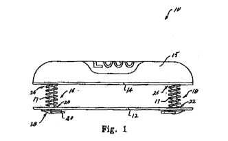
[0042] With
reference to figure 1, a key holder (10) according
to a preferred embodiment of the invention,
comprises two
primary structural elements; a base sheathing plate (12) and an
opposite retainer sheathing plate (14). An interchangeable
accessory compartment cover (15) is releasably attached to at
least the retainer sheathing plate (14). The base sheathing plate
(12) and the retainer sheathing plate (14) are interconnected
when assembled for use in a preferred arrangement, by two locking
pins (16) and (18). It will be understood that the length of
these pins may be selected according to the preferred degree of
key storage.
[0043] The
key holder of this embodiment may be provided with
a number of discs or washers of a thickness similar to that of
keys.,and sufficient in number to fill the space between the base
and retainer sheathing plates. These discs can be replaced with
keys as required.
(0044] The
base sheathing plate (12) preferably comprises a
substantially flat extruded elongate plate provided with
apertures (20) and (22) proximate opposite ends of the base
sheathing plate (12). Locking pins (16) and (18) may pass through
these apertures when the key holder (10) is assembled for use.
Each of locking pins (16) and (18) may be operable between a
. first locked position (as shown in figures 1 and 2) and a second
unlocked position.
CA 02892957 2015-05-28
WO 2013/003907
PCT/AU2012/000809
- 13 -
[0045] Base sheathing plate (12) may be of a flexible material
to allow ease of. access to rotate stored keys into a position for
USG as.shown in figures 6 and 7. To accommodate this flexibility,
apertures (20) and (22) may be in the form of slots.
[0046] The retainer sheathing plate (14) may also comprise a
substantially flat elongate plate and is of substantially similar
size to the size of the base sheathing plate (12). It also may be
provided with corresponding apertures (24) and (26) proximate the
opposite ends of the plate. These apertures align with the
apertures (20) and (22) in the base sheathing plate (12) when the
key holder (10) is assembled for use.
[0047] As can be seen from figures 3, 4 and 5, the apertures
(24) and (26) include locking elements, preferably diametrically
opposed projecting elements (28), adapted to engage with
complementary engaging elements (30) of the locking pins (16,18).
[0048] With particular reference to figure 5, each locking pin
(16,18) comprises a shaft portion (36) and a head portien (38)
which is of a larger diameter than the shaft portion. The
diameter of the shaft portion (36) is chosen as being less than
the typical diameters of those apertures provided in keys by
which means keys may be threaded onto a key ring or suspended on
a hook for example.
[0049] An end of the shaft portion (36), distal from the head
portion (38), is provided with the abovementioned complementary
engaging elements (30). In a preferred arrangement, the engaging
elements (30) of the locking pins comprise an annular groove (32)
with slots (34) between the annular groove and the outer end of
the pins. These diametrically opposed slots (34) correspond to
the projecting elements (28).
=
CA 02892957 2015-05-28
WO 2013/003907
PCT/AU2012/000809
- 14 -
[ 0050] By this arrangement, a locking pin may be inserted into
the apertures (24, 26) when the slots (34) are rotated into
alignment with the projecting elements (28). Turning the pin
through ninety degrees then captures the projecting elements (28)
in the groove (32), thereby securing the locking pins to the
retaining sheathing plate (14).
[0051] Head portion (38) is provided with a grasping element
(40) which is operable between an outwardly projecting position
relative the head portion (38) as shown in figure 5, and a
retracted position as shown in figures 1 and 2. In this latter
position the grasping element (40) lies against the surface of
= the base sheathing plate (12). Preferably, grasping element (40)
is in the form of a semi-circular ring, pivotally attached to the
head portion and provided with biasing means (not shown) towards
the retracted position.
10052) Preferably, the holder (10) is provided with spring
means, disposed between the base sheathing plate (12) and the
retaining sheathing plate (14), which urge any keys retained
between the plates against the base sheathing plate (12) and act
to retain the keys in their sheathed position. Preferably, as
best seen in figure 6, the spring means are in the form of light
coil compression springs (17) which locate around the locking pin
shafts and serve to.prevent both the rattling of keys (48) and
restrict their rotation out of the holder when not required for
use. Preferably, springs (17) are captive in that they are
attached at their base to the retaining sheathing plate (14).
[0053] With reference now to figures 4, 4A and 5, the second,
or opposite side of retainer sheathing plate (14) is provided
with engagement structures in the form of lipped slots (42),
along its opposing edges for attachment of the removable
accessory compartment cover (15).
=
CA 02892957 2015-05-28
WO 2013/003907
PCT/AU2012/000809
- 15 -
f 0054 ) Preferably, removable accessory compartment cover (15)
is of a semi-rigid material forming a shell open at its underside
and provided along its lower opposing edges with complementary
engagement structures (44) which may be clipped into or slid onto
the lipped slots (42). Alternatively, the removable accessory
compartment may include a sliding closure (not shown) at the base
of the shell so as to retain an article in the compartment when
this is released from the engagement structures (42).
[0055] Preferably the shell of removable accessory compartment
cover (15) is generally arcuate in profile and rounded at its
outer ends to form provide a comfortable grip in the hand. The
shell provides a storage space between an inside surface of the
removable accessory cover and the second or opposite side of the
retainer sheathing plate (14).
(0056j In an alternative preferred embodiment shown in figure
8, the base sheathing and retainer sheathing plates are each
provided on their outward facing surfaces with engagement
structures such as shown in figure 5 adapted to releasably retain
similar accessory covers so as to provide two accessory
compartments.
(00571 Typically, the key holder of the invention will be
provided with an initial, or default accessory compartment cover
or covers. A default cover may or may not carry indicia.
Participating retail outlets may provide a range of optional
interchangeable covers which are compatible with the cover
retaining elements of the key holder.
CA 02892957 2015-05-28
WO 2013/003907
PCT/AU2012/000809
- 16 -
10058) In another preferred arrangement, optional novere may
be in the form of an elasticized flexible sheath, for example of
fabric, which may be stretched over the initially provided
default cover or covers.
[0059] In still another preferred embodiment, the optional
cover may be a polymer film provided with a self adhesive surface
protected prior to use by a peel-off protective layer.
[0060] As noted above, optional covers may be provided in a
range of different colours and textures as well as carrying
company logos, advertising or personalising indicia. Thus for
example, a cover may be provided in the colours and the logo of a
favoured sporting team, or with the image of a favoured celebrity
figure.
[0061] Optional interchangeable covers may be provided not
only for the accessory compartment of the key holder, but also
for the outward facing side of the base sheathing plate for
embodiments which only provide for a single compartment.
[0062] The key holder (10) of the invention may be made of any
suitable material including metallic and polymer materials.
[0063] Although the above description has focused on the
retention of keys between the sheathing plates of the key holder,
it will be appreciated that other useful articles of similar size
to a key may conveniently be stored in .the holder. Thus for
example small accessory tools such as scissors, nail file,
penknife blade or a suspension hook, may be threaded onto the
locking pins.
CA 02892957 2015-05-28
WO 2013/003907 PCT/AU2012/000809
- 17 -
Further modifications and improvements can include the following:
= The storage of electronic and microchip technology within
the sheathing plate covers. With reference to Figure 9, the
technology can include a power supply/ battery charger device
(60) for charging external devices such as mobile phones (61) via
cable (62). The technology may also include a microprocessor
based device (63) in communication with a transmitter (64) for
maintaining radio communication with a mobile phone (65) thereby
to enhance or supplement the capabilities of the mobile phone. In
one instance, at least some of the functionality of a smart phone
can be incorporated within the microprocessor based device (63)
thereby permitting the mobile phone (65) to be smaller for a
given level of capability. In a further particular form the
microprocessor based device (63) can include all the
functionality of a mobile phone sufficient that the key holder
can function as a mobile telephone. In a particular form this can
include short range communication functionality as well such as
' "Bluetooth" or Near Field Communication (NFC) thereby to
=
communicate with headsets, point of sale payment facilities and
the like. The microprocessor based device (63) can further
include GPS or similar location capability. This would allow the
device to act for example as an emergency locator. The device
(63) may also act to provide encoding capability as used to
secure banking transactions. The shell (15) may also enclose a
microchip device (66) encoded to facilitate secure banking
transactions or secure door entry or the like. Other electronic
devices can include a laser pointer, an audio speaker and a lost
key locator. As earlier described, non-electronic devices that
may be housed within the shell can additionally include
cosmetics, a mirror, a pen and most other compact items for
personal use.
CA 02892957 2015-05-28
WO 2013/003907
PCT/AU2012/000809
- 18 -
=
= By way of non-limiting example, items both electronic and
non-electronic which may be housed within the shell may include:
o iPad/ iPhone/ iPod accessories
o Cisco Console cables/IT troubleshooting cables used for
vendor specific devices
o Portable sewing kit
o Universal Plugin charger for mobile phones/iPads/spare
battery compartment
o Miniaturized camera
o Universal remote control
o Micro tools
o Multi purpose cables (such as a USE cable that rolls
up)
o Cosmetics
o Liquid compartment for cologne, hand sanitizer
o Pocket knife
o Tools - miniature stud finder, laser measurement device
o Mirror
o Torch, flash light
o Alarm transmitters
o Key locator
o MP3 player
o Lighter
o USE storage
o Retractable lanyard
=
o Retractable spring hook
o Belt clip
o RSA Security token
o Random number generator used in two factor
authentication with LED display
o Floatation device/inflatable devices
o Microchip ID technology such as chips for access doors,
swipe card chips, identification chips to start cars,
ID chips for access to gym clubs
CA 02892957 2015-05-28
WO 2013/003907
PCT/AU2012/000809
- 19 -
=
o Storage for medication, pills, mints
o Storage for small personal items - money notes,
cigarettes, tobacco
o Miniaturized tools (screw driver)
= o Pen/high lighter/ruler
o Tape measure
o Spirit level
o Watch/Alarm clock with calendar
o Mobile device signal antennae (booster)
O Laser pointer and presentation remote control
o Bluetooth remote control for Bluetooth enabled devices
o Mobile phone stand
o Hi-Definition Bluetooth hands free speakerphone for
mobile phones
o Electronic display (LCD/LED) for photos
o Mini radio transmitters/receivers
O Book lights
o Magnet attachment to stick to a fridge
o Bottle opener
o Cork Screw
o Third party interfacing attachment capability (Eg Swiss
Army knife attachment)
o 3G modem with SIN capability (as an alternative to the
standard 3G/4G/LTE modem)
o Toiletries
o Tooth brush
o Tampon holder
o Personal distress alarm/panic device
o Tracking device
o Micro Portable speakers
o Lint remover
o Comb
o Voice recorder
o Compass
CA 02892957 2015-05-28
WO 2013/003907
PCT/AU2012/000809
- 20 -
o Electronic Multi function device with interchangeable
software (le with an interface) - while most smart
phones are able to do a function, you can't actually
use the function while on the phone
o Bluetooth speaker phone
o Pedometer (similar to the idea of the Nike + iPod
Accessory)
o Retractable Magnifying glass
o Prescription lenses
o Micro Bluetooth touch pad (as a substitute for a mouse
or track pad)
= As earlier described, the sheathing plate (12) can comprise
of a flexible material incorporating slotted holes for the
passing through of the locking pins, so as to allow the retaining
sheathing plate to flex outwardly and hence gain access to the
stored keys.
INDUSTRIAL APPLICABILITY
[0064] The key holder (10) of embodiments of the invention
provides convenient storage for a number of keys as shown in
figures 6 and 7. In a preferred embodiment described above and -
indicated in the drawings, the holder provides for two stacks of
keys (50) and (52), threaded onto the respective locking pins
(16) and (18).
[0065] To add a key to the holder, the locking pin, to which
the key is to be added, is unlocked by turning the grasping
element and withdrawing the outer portion of the locking pin from
. the retaining sheathing plate. The base sheathing plate can then
be swung or flexed out of alignment with the retaining sheathing
plate to access the released locking pin, and the key threaded
onto the pin. The base sheathing plate (12) is then swung or
CA 02892957 2015-05-28
WO 2013/003907
PCT/AU2012/000809
- 21 -
flexed back into alignment and the locking pin re-secured to the
retaining sheathing plate (14).
(0066) As noted above, the storage space provided by the
removable cover portion (15) may be used to retain small personal
Items such as a mirror, an LED torch, alarm transmitter, USB
device, retractable lanyard and coins for example.
(00671 The above describes only some embodiments of the
present invention and modifications, obvious to those skilled in
the art, can be made thereto without departing from the scope of
the present invention,