Note: Descriptions are shown in the official language in which they were submitted.
CA 02892997 2015-05-28
SYSTEMS AND METHODS FOR STIMULATING A MULTI-ZONE
SUBTERRANEAN FORMATION
Field of the Disclosure
[0003] The present disclosure is directed generally to systems and
methods for stimulating
a subterranean formation, and more particularly to systems and methods that
utilize a
perforation device and an isolation sleeve to stimulate the subterranean
formation.
Background of the Disclosure
[0004] A well may be utilized to produce one or more reservoir fluids,
such as liquid
and/or gaseous hydrocarbons, from a subterranean formation. The well may
include a
wellbore, which extends between a surface region and the subterranean
formation, and a
production casing that extends within the wellbore and defines a casing
conduit.
[0005] During construction and/or operation of the well, it may be
desirable to stimulate
and/or fracture the subterranean formation, such as to increase a flow, or
production, rate of
reservoir fluids therefrom. In general, this stimulating includes providing a
stimulating fluid
to the casing conduit, with the stimulating fluid flowing from the casing
conduit into the
subterranean formation to thereby stimulate the subterranean formation.
Illustrative examples
of stimulation processes include fracturing the formation and acidizing, or
acid treating, the
formation. Typically, this stimulating process may be repeated a plurality of
times along a
length of the production casing to stimulate a plurality of zones of the
subterranean formation.
[0006] A number of processes have been utilized to stimulate
subterranean formations.
While these processes may be effective under certain conditions, they may be
ineffective
under others. As an illustrative, non-exclusive example, a well may include a
wellbore with a
long horizontal section. This long horizontal section may extend within the
subterranean
formation, and it may be desirable to stimulate a plurality of zones of the
subterranean
formation that may be distributed along the length of the horizontal section.
[0007] Traditional stimulating processes may include establishing fluid
communication
between the casing conduit and a given zone of the subterranean formation,
providing the
stimulating fluid to the given zone of the subterranean formation to stimulate
the given zone
of the subterranean formation, and then fluidly isolating at least a portion
of the casing
-1-
CA 02892997 2015-05-28
conduit from the subterranean formation. This process may be repeated a
plurality of times
along a length of the horizontal section to stimulate the plurality of zones
of the subterranean
formation.
100081 Generally, the traditional stimulating processes fluidly isolate
the portion of the
casing conduit from downhole portions of the casing conduit, and corresponding
regions of
the subterranean formation that are in fluid communication therewith, using
isolation plugs or
using isolation balls and seats. Isolation plugs may include and/or be
expandable plugs that
may be located within the casing conduit and subsequently expanded to fill a
portion of the
casing conduit, thereby blocking fluid flow therepast. Isolation balls may
include and/or be
elastomeric balls that are sized to fit within the casing conduit and to seal
with a respective
seat that is sized to receive the isolation ball to block the flow of fluid
therepast.
[0009] However, as the length of the well is increased, setting the
required number of
isolation plugs becomes increasingly difficult and/or expensive and may
inhibit economic
and/or efficient stimulating of the subterranean formation. Moreover, the
isolation plugs must
be removed from the casing conduit, typically by time-consuming and/or
expensive processes
that include drilling the isolation plugs from the casing conduit, prior to
production of the
reservoir fluid from the subterranean formation.
[0010] Similarly, isolation balls and seats rely on progressively
smaller balls and seats to
stimulate a desired number of zones of the subterranean formation. Thus, there
is a practical
limit to the number of zones that may be stimulated with isolation balls and
seats while still
permitting sufficient fluid flow rates within the casing conduit. In addition,
the progressively
smaller seats effectively may limit access to portions of the casing conduit
that are downhole
therefrom, as many downhole assemblies simply may be too large to fit, or
flow, through the
seats. Furthermore, these seats often must be removed from the casing conduit
prior to
production of the reservoir fluid from the subterranean formation, and doing
so increases the
overall cost of the stimulation process. Thus, there exists a need for
improved systems and
methods for stimulating a subterranean formation.
Summary of the Disclosure
100111 Systems and methods for stimulating a subterranean formation are
disclosed
herein. The methods include providing a stimulating fluid stream to a casing
conduit, which
-2-
CA 02892997 2015-05-28
is defined by a production casing that extends within the subterranean
formation, to increase a
fluid pressure within the casing conduit. The methods further include locating
an isolation
device on an isolation sleeve to fluidly isolate a downhole portion of the
casing conduit from
an uphole portion of the casing conduit and opening an injection port that is
associated with
the isolation sleeve to permit an injection port fluid flow from the casing
conduit into the
subterranean formation. The methods also include sealing the injection port
and creating an
uphole perforation in the uphole longitudinal section of the production casing
responsive to
the fluid pressure exceeding a threshold perforating pressure. The systems
include a well that
is formed, at least in part, utilizing the methods.
[0012] In some embodiments, the methods further include stimulating a zone
of the
subterranean formation. In some embodiments, the stimulating includes flowing
the
stimulating fluid stream through the injection port and/or through the uphole
perforation. In
some embodiments, the stimulating fluid stream is a fracturing fluid stream,
and the
stimulating includes fracturing the zone of the subterranean formation. In
some
embodiments, the methods further include providing a proppant to the
stimulated zone of the
subterranean formation. In some embodiments, and during the providing a
proppant, the
methods further include perforating the production casing responsive to the
fluid pressure
within the casing conduit exceeding a threshold screenout pressure. In some
embodiments,
the stimulating includes acidizing, or acid treating, the zone of the
subterranean formation.
[0013] In some embodiments, the methods further include creating at least
one downhole
perforation, and thereby stimulating a zone of the subterranean formation
associated with a
downhole portion of the casing conduit, prior to locating the isolation device
on the isolation
sleeve.. In some embodiments, the downhole perforation is created by a first
perforation
device, the uphole perforation is created by a second perforation device, and
the methods
further include flowing the second perforation device into the casing conduit
while permitting
the injection conduit fluid flow. In some embodiments, the methods further
include receiving
an injection port sealing device on an injection port sealing device seat that
defines a portion
of the injection conduit to seal the injection port.
[0014] In some embodiments, the methods include restricting and/or
blocking fluid flow
through a portion of the casing conduit with a fluid plug. In some
embodiments, the methods
-3-
CA 02892997 2015-05-28
include retaining the sealing device and/or the injection port sealing device
on and/or near a
perforation and/or an injection port sealing device seat, respectively, with
the fluid plug.
[0015] The systems include wells that are formed, at least in part, by
utilizing the
methods. In some embodiments, the systems include casing conduits with flow
control
devices that include a seat for an isolation device and which are configured
to selectively
provide fluid communication with at least one, and optionally a plurality of,
injection port(s).
The injection ports are in fluid communication with the subterranean formation
and are
configured to receive sealing devices to obstruct fluid flow from the casing
conduit
therethrough to the subterranean formation.
Brief Description of the Drawings
[0016] Fig. 1 is a schematic cross-sectional view of illustrative, non-
exclusive examples
of a well that may be utilized with and/or include the systems and methods
according to the
present disclosure.
[0017] Fig. 2 provides a schematic cross-sectional view of illustrative,
non-exclusive
examples of stimulation operations that may include and/or utilize the systems
and methods
according to the present disclosure.
[0018] Fig. 3 provides an additional schematic cross-sectional view of
the stimulation
operations of Fig. 2.
[0019] Fig. 4 provides an additional schematic cross-sectional view of
the stimulation
operations of Fig. 2.
[0020] Fig. 5 provides an additional schematic cross-sectional view of
the stimulation
operations of Fig. 2.
[0021] Fig. 6 provides an additional schematic cross-sectional view of
the stimulation
operations of Fig. 2.
[0022] Fig. 7 provides an additional schematic cross-sectional view of the
stimulation
operations of Fig. 2.
[0023] Fig. 8 provides an additional schematic cross-sectional view of
the stimulation
operations of Fig. 2.
[0024] Fig. 9 provides an additional schematic cross-sectional view of
the stimulation
operations of Fig. 2.
-4-
CA 02892997 2015-05-28
[0025] Fig. 10 is a less schematic representation of illustrative, non-
exclusive examples of
an optional flow control assembly according to the present disclosure in a
first configuration.
[0026] Fig. 11 is a less schematic representation of illustrative, non-
exclusive examples of
an optional flow control assembly according to the present disclosure in a
second
configuration.
[0027] Fig. 12 is another less schematic representation of illustrative,
non-exclusive
examples of an optional flow control assembly according to the present
disclosure in the
second configuration.
[0028] Fig. 13 is a schematic representation of illustrative, non-
exclusive examples of a
portion of a housing body that includes and/or defines a sealing device seat
and may form a
portion of an optional flow control assembly according to the present
disclosure.
[0029] Fig. 14 is a flowchart depicting methods according to the present
disclosure of
stimulating a subterranean formation.
Detailed Description and Best Mode of the Disclosure
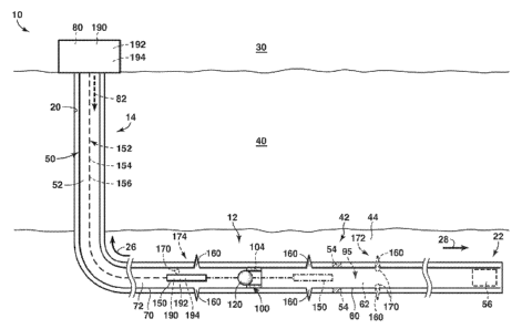
[0030] Figs. 1-13 provide illustrative, non-exclusive examples of wells 10
according to
the present disclosure and/or of stimulation operations according to the
present disclosure that
may be performed within wells 10. Elements that serve a similar, or at least
substantially
similar, purpose are labeled with like numbers in each of Figs. 1-13, and
these elements may
not be discussed in detail herein with reference to each of Figs. 1-13.
Similarly, all elements
may not be labeled in each of Figs. 1-13, but reference numerals associated
therewith may be
utilized herein for consistency. Elements, components, and/or features that
are discussed
herein with reference to one or more of Figs. 1-13 may be included in and/or
utilized with any
of Figs. 1-13 without departing from the scope of the present disclosure.
100311 In general, elements that are likely to be included in a given
(i.e., a particular)
embodiment are illustrated in solid lines, while elements that are optional to
a given
embodiment are illustrated in dashed lines. However, elements that are shown
in solid lines
are not essential to all embodiments, and an element shown in solid lines may
be omitted from
a particular embodiment without departing from the scope of the present
disclosure.
[0032] Fig. 1 is a schematic cross-sectional view of illustrative, non-
exclusive examples
of a well 10 that may be utilized with and/or include the systems and methods
according to
-5-
CA 02892997 2015-05-28
the present disclosure. Figs. 2-9 provide more specific, but still
illustrative, non-exclusive,
examples of stimulation operations that may be performed within well 10 and/or
that may
include and/or utilize the systems and methods according to the present
disclosure. Figs. 10-
13 provide illustrative, non-exclusive examples of an isolation sleeve 100
that includes an
optional injection port 104 according to the present disclosure. When
isolation sleeve 100
includes injection port 104, the isolation sleeve also may be referred to
herein as a flow
control assembly 100.
[0033] In Figs. 1-9, well 10 includes a wellbore 20 that extends between
a surface region
30 and a subterranean formation 42, with the subterranean formation being
present within a
subsurface region 40 (as illustrated in Fig. 1). Subterranean formation 42 may
include a
reservoir fluid 44. Reservoir fluid 44 additionally or alternatively may be
referred to herein
as, and/or may be, a hydrocarbon 44, a liquid hydrocarbon 44, and/or a gaseous
hydrocarbon
44.
[0034] With continued reference to Figs. 1-9, a production casing 50
extends within
wellbore 20 and defines a casing conduit 52 therein. Well 10, wellbore 20,
production casing
50, and/or casing conduit 52 may include a horizontal portion 12 and a
vertical, deviated,
and/or angled portion 14 (as illustrated in Fig. 1). Vertical portion 14 may
extend (at least
substantially) between surface region 30 and subterranean formation 42, while
horizontal
portion 12 may extend (at least substantially) within subterranean formation
42.
[0035] An isolation sleeve 100 is located within and/or defines a portion
of production
casing 50 defines a portion of casing conduit 52, and/or is located between a
first section 60
of the production casing from a second section 70 of the production casing
(and/or operatively
attaches the first section of the production casing to the second section of
the production
casing). First section 60 also may be referred to herein as a first
longitudinal section 60, as a
downhole section 60, and/or as a downhole longitudinal section 60 of the
production casing.
Second section 70 also may be referred to herein as a second longitudinal
section 70, as an
uphole section 70, and/or as an uphole longitudinal section 70 of the
production casing.
[0036] As illustrated in Figs. 1 and 7-9, isolation sleeve 100 may be
configured to receive
an isolation device 120 thereon and/or otherwise in a sealing configuration in
contact
therewith. When present on isolation sleeve 100, isolation device 120 may be
configured to
-6-
CA 02892997 2015-05-28
fluidly isolate a first, or downhole, portion 62 of casing conduit 52 from a
second, or uphole,
portion 72 of the casing conduit. As discussed in more detail herein,
isolation sleeve 100
further may be configured to selectively provide fluid communication between
casing conduit
52 and subterranean formation 42 via an injection port 104 (and optionally a
plurality of
injection ports 104) that may be associated therewith (as illustrated in Figs.
1, 8, and 10-13).
[0037] Production casing 50 may include, or define, one or more
perforations 160 therein.
In addition, casing conduit 52 may contain one or more sealing devices 170,
which may be
configured to seal at least a portion of the one or more perforations 160. As
an illustrative,
non-exclusive example, and as indicated in Figs. 1 and 4-9 at 172, sealing
devices 170 may
include and/or be seated sealing devices that may be located on a respective
perforation 160
and limit (or even prevent) fluid flow through the respective perforation from
the casing
conduit into the subterranean formation. Additionally or alternatively, and as
indicated in
Figs. 1 and 4 at 174, sealing devices 170 also may include and/or be free
sealing devices that
may not be located on a respective perforation 160, may not restrict or
otherwise limit fluid
flow through perforation 160, and/or may be free to move within casing conduit
52. As
illustrated, sealing devices 170 may be sized to permit flow of the sealing
devices past a
perforation device 150 that is within casing conduit 52 (such as within an
annular space that
may be defined between the perforation device and production casing 50).
[0038] As indicated in dashed lines in Fig. 1, well 10 further may
include (and/or casing
conduit 52 may contain) an isolation plug 56. Isolation plug 56 may be located
and/or
configured to fluidly isolate an uphole portion of casing conduit 52 (such as
a portion of the
casing conduit that is located in an uphole direction 26 from the isolation
plug) from a
downhole portion of casing conduit 52 (such as a portion of the casing conduit
that is located
in a downhole direction 28 from the isolation plug). Additionally or
alternatively, isolation
plug 56 may be located at, or near, a terminal end 22 of production casing 50,
casing conduit
52, and/or wellbore 20.
100391 As also illustrated in dashed lines in Fig. 1, in some
embodiments and/or
according to some methods according to the present disclosure, well 10 further
may include at
least one optional fluid plug 95. Fluid plug 95 is formed from a gelled or
otherwise thickened
or stiffened fluid that inhibits fluid flow therethrough with the fluid plug
being configured to
-7-
CA 02892997 2015-05-28
dissolve or otherwise disperse after a given time period and/or responsive to
exposure to a
release agent. When present, fluid plug 95 may be configured to restrict
and/or block fluid
flow through a portion of casing conduit 52 that includes the fluid plug.
Additionally or
alternatively, fluid plug 95 also may be configured to retain sealing devices
170 on respective
perforations 160 despite fluctuations in a pressure within the casing conduit.
As illustrated in
Figs. 1-9, well 10 also may include one or more packers 54 that may be located
within an
annular space that is defined between production casing 50 and wellbore 20 and
may be
configured to limit fluid flow therepast.
[0040] Returning to Fig. 1, well 10 and/or perforation device 150
thereof further may
include, be associated with, and/or be in communication with a controller 190
that may be
programmed and/or configured to control the operation of at least a portion of
the well. In
addition, a detector 192 may be configured to detect a fluid pressure within
casing conduit 52
and/or to provide the fluid pressure to controller 190.
[0041] As discussed in more detail herein, it may be desirable to
stimulate subterranean
formation 42, such as to increase a permeability thereof and/or to increase a
production of
reservoir fluid 44 therefrom. Thus, well 10 further may include and/or be in
fluid
communication with a stimulating fluid supply system 80 that is configured to
provide a
stimulating fluid stream 82 to casing conduit 52. As illustrative, non-
exclusive examples,
stimulating fluid stream 82 may include and/or be water, a proppant, an acid,
a surfactant,
and/or a foam. When well 10 includes stimulating fluid supply system 80,
detector 192 may
be configured to detect the fluid pressure of stimulating fluid stream 82
within the casing
conduit and/or proximal to perforation device 150.
[0042] As illustrated in Figs. 1-5 and 7-9, well 10 and/or casing
conduit 52 thereof further
may include and/or contain perforation device 150, which may be configured to
create
perforations 160 within production casing 50. Perforation device 150 may
include any
suitable structure. As an illustrative, non-exclusive example, perforation
device 150 may
include and/or be a perforation gun that includes one or more perforation
charges. As an
illustrative, non-exclusive example, perforation device 150 may include a
plurality of
perforation charges that are configured to create a respective plurality of
perforations 160
within production casing 50. This may include at least three, at least four,
at least six, at least
-8-
CA 02892997 2015-05-28
eight, at least ten, at least twelve, at least fifteen, at least twenty, at
least twenty-five, or at
least thirty perforation charges. As discussed in more detail herein, the
systems and methods
according to the present disclosure may include creating perforations 160 in a
plurality of
sections of production casing 50, and a single perforation device 150 may be
utilized (or re-
used) at different times to create perforations 160 in at least a subset of
the plurality of
sections of the production casing. This may include creating perforations 160
in at least two,
at least three, at least four, at least five, at least six, at least eight, or
at least ten sections of the
production casing.
[0043] As additional illustrative, non-exclusive examples, perforation
device 150 may be
operatively attached to a tether 152, such as a working line (or wireline) 154
and/or tubing
156. As another illustrative, non-exclusive example, perforation device 150
may include
and/or be an autonomous perforation device 150, which is not tethered or
otherwise
physically and/or mechanically connected to surface region 30. Additionally or
alternatively,
perforation device 150 further may be actuated in any suitable manner. As
illustrative, non-
exclusive examples, perforation device 150 may be electrically actuated (such
as via working
line 154), may be hydraulically actuated, may be actuated remotely, and/or may
be actuated
autonomously.
[0044] It is within the scope of the present disclosure that perforation
device 150 may be
controlled and/or actuated in any suitable manner. As an illustrative, non-
exclusive example,
controller 190 and/or detector 192 may be associated with, included within,
and/or operatively
attached to perforation device 150 and may control the operation thereof
Additionally or
alternatively, controller 190 and/or detector 192 may be located in, or
proximal to, surface
region 30 but may be in communication with the perforation device. It is
within the scope of
the present disclosure that controller 190 may control the operation of well
10 and/or
perforation device 150 in any suitable manner, such as through the use of
methods 200, which
are discussed in more detail herein.
[0045] As another illustrative, non-exclusive example, perforation
device 150 may
include and/or be in communication with a perforation device control structure
194 that is
configured to control the operation thereof. This may include any suitable
active and/or
actively controlled perforation device control structure, as well as any
suitable passive and/or
-9-
CA 02892997 2016-10-12
passively controlled perforation device control structure. As an illustrative,
non-exclusive
example, perforation device control structure 194 may be programmed, selected,
and/or
configured to automatically actuate perforation device 150 responsive to the
fluid pressure
within casing conduit 52 exceeding a threshold perforating pressure and/or a
threshold
screenout pressure.
[0046] Fluid plug 95, when present, may include any suitable structure
that may limit,
block, restrict, and/or occlude fluid flow therepast and/or that may retain
balls sealers 170 on
respective perforations 160. As an illustrative, non-exclusive example, fluid
plug 95 may be
formed from a sealing fluid that may be provided to casing conduit 52 from
surface region 30.
As an illustrative, non-exclusive example, the sealing fluid may include
and/or be a
crosslinking solution, such as a crosslinking polymer solution, a crosslinking
gel solution,
and/or a borate gel solution, that may be selected to crosslink within the
casing conduit.
[0047] As another illustrative, non-exclusive example, and as discussed,
fluid plug 95
may be selected to retain sealing devices 170 on perforations 160 despite
fluctuations in
pressure within casing conduit 52 and/or despite fluctuations in a pressure
differential across
sealing devices 170 between casing conduit 52 and subterranean formation 42.
As an
illustrative, non-exclusive example, fluid plug 95 may be selected to retain
the sealing devices
on the perforations even when the pressure differential would be insufficient
to retain the
sealing devices on the perforations without the presence of the fluid plug. As
another
illustrative, non-exclusive example, fluid plug 95 may be selected to retain
the sealing devices
on the perforations during removal of a downhole assembly, such as perforation
device 150,
from the casing conduit.
[0048] As yet another illustrative, non-exclusive example, the systems
and methods
according to the present disclosure may include locating and/or forming fluid
plug 95 within
casing conduit 52 responsive to a malfunction of one or more components of
well 10, such as
but not limited to perforation device 150, isolation sleeve 100, etc.
Additional illustrative,
non-exclusive examples of fluid plugs that may be utilized with and/or
included in the
systems and methods according to the present disclosure are disclosed in U.S.
Patent
Publication No. 2015/0292293.
-10-
CA 02892997 2015-05-28
[0049] As discussed in more detail herein, perforation device 150,
isolation device 120,
and/or sealing devices 170 may be selected to be mobile and/or to be
selectively located
and/or present within casing conduit 52. As an illustrative, non-exclusive
example, and as
illustrated in dash-dot lines in Fig. 1 and solid lines in Figs. 2-5,
perforation device 150 may
be located downhole from isolation sleeve 100 and/or may be configured to
create
perforations 160 within downhole section 60 of production casing 50. Thus,
perforation
device 150 and/or isolation sleeve 100 may be sized to permit perforation
device 150 to be
conveyed past the isolation sleeve within casing conduit 52.
[0050] As another illustrative, non-exclusive example, and as
illustrated in solid lines in
Figs. 1 and 8-9 and in dashed lines in Fig. 7, perforation device 150 may be
located uphole
from isolation sleeve 100 and/or may be configured to create perforations 160
within uphole
section 70 of production casing 50. It is within the scope of the present
disclosure that the
same perforation device 150 may be utilized to form perforations within
downhole section 60
and uphole section 70 of production casing 50. However, it is also within the
scope of the
present disclosure that, as discussed herein, a first perforation device 150
may be utilized to
create perforations in downhole section 60 and that a second perforation
device 150 may be
utilized to create perforations in uphole section 70 of production casing 50.
[0051] As discussed herein and illustrated in Fig. 1, well 10 may
include a horizontal (or
at least substantially horizontal) portion 12 and a vertical (or at least
substantially vertical)
portion 14, and downhole section 60 and/or uphole section 70 of production
casing 50 may be
located within (or at least substantially within) horizontal portion 12. It is
within the scope of
the present disclosure that wellbore 20, production casing 50, and/or casing
conduit 52 may
define any suitable length, which also may be referred to herein as a
longitudinal length. As
illustrative, non-exclusive examples, the length may be at least 1000 meters
(m), at least 1500
m, at least 2000 m, at least 2500 m, at least 3000 m, at least 3500 m, at
least 4000 m, at least
4500 m, or at least 5000 m. Additionally or alternatively, it is also within
the scope of the
present disclosure that a distance along production casing 50 between the
surface region and
first portion 60 and/or second portion 70 may define any suitable proportion
of the length of
the production casing. As illustrative, non-exclusive examples, the distance
may be at least
25%, at least 30%, at least 35%, at least 40%, at least 45%, at least 50%, at
least 55%, at least
-11-
CA 02892997 2015-05-28
60%, at least 65%, at least 70%, at least 75%, at least 80%, at least 85%, at
least 90%, at least
95%, or at least 99% of a/the length of the production casing.
[0052] As discussed in more detail herein, it may be desirable to
stimulate and/or fracture
a plurality of zones of a subterranean formation. In addition, and as a length
of a well is
increased, a number of zones to be stimulated may increase (or may increase
proportionate to
the length of the well). In general, fracturing, acidizing, and/or other
stimulation of the
subterranean formation may be accomplished more efficiently by selectively
providing fluid
communication between the casing conduit and a given zone of the subterranean
formation.
This may include establishing the fluid communication, stimulating, the given
zone of the
subterranean formation (such as by providing a stimulating fluid stream from
the casing
conduit into the given zone of the subterranean formation), and subsequently
fluidly isolating
the given zone of the subterranean formation from the casing conduit. This
process may be
repeated a plurality of times to stimulate and/or fracture a desired number of
zones of the
subterranean formation. Thus, the casing conduit may be fluidly isolated from
the
subterranean formation a plurality of times during an overall stimulation
process and/or
during stimulation of the desired number of zones of the subterranean
formation.
[0053] As also discussed, traditional stimulating processes may fluidly
isolate a portion of
the casing conduit from the subterranean formation using isolation plugs
and/or using
isolation balls and seats. Each of these traditional approaches suffers from
inherent
limitations associated with the use thereof in extended reach wells that may
include long
wellbores. Additionally or alternatively, each of these traditional approaches
also suffers
from inherent inefficiencies that may be associated with the use thereof
and/or that may
increase a cost associated with use thereof
[0054] As an illustrative, non-exclusive example, and while isolation
plugs may be
effective at fluidly isolating an uphole portion of a casing conduit from a
downhole portion of
a casing conduit, it may be necessary to remove a perforation device (or other
downhole
assembly) that may be present within the casing conduit from the casing
conduit prior to
insertion and/or use of the isolation plugs within the casing conduit,
significantly increasing
an overall time and/or cost associated with the stimulation process. Often,
this removal of the
perforation device and insertion of the isolation plug must be repeated for
each zone of the
-12-
CA 02892997 2015-05-28
subterranean formation that is to be stimulated, thus generating a casing
conduit that includes
a plurality of isolation plugs located therein.
100551 As another illustrative, non-exclusive example, and subsequent to
stimulation of
the desired number of zones of the subterranean formation, the plurality of
isolation plugs
often must be removed from the casing conduit prior to producing a reservoir
fluid from the
subterranean formation. As an illustrative, non-exclusive example, a drill rig
may need to be
utilized to drill the plurality of isolation plugs from the casing conduit.
Once again, this
increases the cost and/or time required to complete the stimulation operation.
[0056] As yet another illustrative, non-exclusive example, and while
isolation balls and
seats also may be effective at fluidly isolating the uphole portion of the
casing conduit from
the downhole portion of the casing conduit, it may be necessary to utilize one
isolation ball
and seat for each zone of the subterranean formation that is to be stimulated
and/or to utilize a
large number of isolation balls and seats during the stimulation process.
Isolation balls and
seats rely upon progressively smaller seats that may be sealed by
progressively smaller balls.
As such, a given seat may be sized to permit isolation balls that are
associated with seats that
are located downhole therefrom to flow therethrough while, at the same time,
forming a fluid
seal with an isolation ball that is sized to seal therewith. Thus, there are
practical limitations
on a total number of isolation balls and seats that may be utilized for a
given diameter of the
production casing.
[0057] The small size of many of the seats may preclude access to portions
of the casing
conduit that may be downhole therefrom by a downhole assembly, such as a drill
string and/or
a perforation gun, thereby complicating wellbore drilling and/or completion
processes. In
addition, and similar to the isolation plugs, the seats often must be removed
from the casing
conduit, such as by drilling, prior to production of the reservoir fluid from
the subterranean
formation. Once again, this increases the overall time and/or cost associated
with the
stimulation operation.
100581 With this in mind, Figs. 2-9 are schematic cross-sectional views
of illustrative,
non-exclusive examples of stimulation operations and/or process flows that may
include
and/or utilize the systems and methods according to the present disclosure.
The stimulation
operations of Figs. 2-9 may permit stimulation of long and/or extended reach
wells without
-13-
CA 02892997 2015-05-28
the need to locate a plurality of isolation plugs (such as, but not limited
to, bridge plugs)
within the casing conduit and/or without the need to utilize an isolation ball
and seat for each
stimulated zone of the subterranean formation. Additionally or alternatively,
the stimulation
operations of Figs. 2-9 also may permit stimulation of the wells without the
need to remove
and/or drill the isolation plugs and/or the seats from the casing conduit
subsequent to
completion of the stimulation operation.
10059] In Fig. 2, perforation device 150 has been located within casing
conduit 52 and
downhole from isolation sleeve 100 (i.e., within downhole portion 62 of casing
conduit 52
that is defined by downhole section 60 of production casing 50). Subsequently,
and as
illustrated in Fig. 3, perforation device 150 may be utilized to create, form,
and/or generate
one or more perforations 160 within downhole section 60 of production casing
50.
100601 As discussed in more detail herein, and prior to creation of
perforations 160 within
downhole section 60, stimulating fluid 82 may be provided to casing conduit 52
to increase
the fluid pressure therein, and perforations 160 may be created responsive to
the fluid pressure
exceeding a threshold perforating pressure. Thus, subsequent to creation of
perforations 160,
stimulating fluid 82 may flow through perforations 160 into subterranean
formation 42 to
create one or more fractures 90 therein.
10061] After creation of fractures 90, and as illustrated in Fig. 4, one
or more sealing
devices 170 may be located on perforations 160. This may include flowing
and/or otherwise
conveying sealing devices 170 past perforation device 150 within casing
conduit 52 and/or
through the annular space that is defined between perforation device 150 and
production
casing 50, as discussed herein. In addition, perforation device 150 may be
moved and/or
translated in uphole direction 26 within the casing conduit. Subsequently, and
as illustrated in
Fig. 5, perforation device 150 may be utilized to create one or more
additional perforations
160 within production casing 50 and stimulating fluid 82 may be provided to
subterranean
formation 42 through perforations 160 to create one or more additional
fractures 90 within the
subterranean formation. This may include providing the stimulating fluid to
the casing
conduit prior to formation of perforations 160 and/or creating perforations
160 responsive to
the fluid pressure within the casing conduit exceeding the threshold
perforating pressure, as
discussed herein.
-14-
CA 02892997 2015-05-28
[0062] After creation of fractures 90, and as illustrated in Fig. 6,
perforation device 150,
which also may be referred to herein as and/or may be a first perforation
device 150, may be
removed from casing conduit 52. Then, and as illustrated in Fig. 7, an
isolation device 120
may be located on isolation sleeve 100 to fluidly isolate downhole portion 62
of casing
conduit 52 from uphole portion 72 of the casing conduit. This may include
flowing the
isolation device within casing conduit 52, from surface region 30 (as
illustrated in Fig. 1),
and/or into contact with isolation sleeve 100.
[0063] As illustrated in dashed lines in Fig. 7, the stimulation
operation further may
include flowing perforation device 150, which also may be referred to herein
as and/or may
be a second perforation device 150, into casing conduit 52 at least partially
concurrently with
locating isolation device 120 on isolation sleeve 100. As an illustrative, non-
exclusive
example, and as illustrated in Fig. 7 at 158, second perforation device 150
may be operatively
attached to and/or may form a portion of isolation device 120.
100641 As another illustrative, non-exclusive example, and as
illustrated in Fig. 7 at 159,
second perforation device 150 may be separate and/or distinct from isolation
device 120.
When second perforation device 150 is separate from isolation device 120, the
stimulation
operation additionally or alternatively may include tractoring the perforation
device into the
casing conduit, with the tractoring being performed at least partially
concurrently with and/or
after flowing the isolation device through the casing conduit and/or locating
the isolation
device on the isolation sleeve.
[0065] Additionally or alternatively, and as illustrated in Fig. 8,
isolation sleeve 100 may
be configured to selectively provide fluid communication between casing
conduit 52 and
subterranean formation 42 via at least one injection port 104, and this fluid
communication
may be initiated responsive to isolation device 120 being received on
isolation sleeve 100
and/or responsive to at least a threshold pressure drop (or differential)
being established
across isolation device 120 after isolation device 120 has been received on,
or otherwise
engaged in a sealing configuration with, isolation sleeve 100. Injection port
104 may permit
an injection conduit fluid flow of stimulating fluid 82 from casing conduit 52
into
subterranean formation 42, thereby permitting perforation device 150 to be
flowed through
the casing conduit subsequent to the isolation device being located on the
isolation sleeve
-15-
CA 02892997 2016-10-12
and/or subsequent to the isolation device fluidly isolating downhole portion
62 of casing
conduit 52 from uphole portion 72 of the casing conduit. In addition,
injection port 104 may
be sized to maintain at least a threshold pressure drop thereacross when the
injection conduit
fluid flow is flowing therethrough. This threshold pressure drop may be
selected to (or to be
sufficient to) retain sealing devices 170 that may be uphole from isolation
sleeve 100 on
respective perforations 160 that may be associated therewith and/or to retain
isolation device
120 on isolation sleeve 100.
[0066] Additionally or alternatively, and as illustrated in dashed lines
in Fig. 8, the
injection conduit fluid flow also may create one or more additional fractures
90 within the
subterranean formation. When isolation sleeve 100 includes injection port 104,
and as
discussed in more detail herein, the injection port subsequently may be sealed
to restrict fluid
flow therethrough, such as through the use of a sealing device. Illustrative,
non-exclusive
examples of isolation sleeves 100 that also may include and/or define
injection ports 104 are
disclosed in U.S. Patent Publication No. 2015/0285029.
[0067] Subsequently, and as illustrated in Fig. 9, perforation device 150
may be utilized to
create one or more additional perforations 160 within production casing 50,
and stimulating
fluid 82 may be provided to subterranean formation 42 through perforations 160
to create one
or more additional fractures 90 within the subterranean formation. This may
include
providing the stimulating fluid to the casing conduit prior to formation of
perforations 160
and/or creating perforations 160 responsive to the fluid pressure within the
casing conduit
exceeding the threshold perforating pressure, as discussed herein.
[0068] Figs. 10-13 provide less schematic but still illustrative, non-
exclusive examples of
an optional flow control assembly 100 (or isolation sleeve 100) according to
the present
disclosure that may form a portion of a production casing 50 and/or of a well
10. Flow
control assembly 100 may include any suitable structure that may form a
portion of
production casing 50, that may be configured to selectively control a fluid
flow (such as in
uphole direction 26 and/or downhole direction 28) within casing conduit 52,
and/or that may
be configured to selectively control a fluid flow between casing conduit 52
and subterranean
formation 42.
-16-
CA 02892997 2015-05-28
[0069] The flow control assemblies 100 of Figs. 10-13 may include a
housing 110 that
includes a housing body 112. Housing body 112 defines an inner surface 126 of
housing 110,
which defines a housing conduit 320 that forms a portion of casing conduit 52.
The housing
body also defines an outer surface 128 of housing 110, which may be opposed to
inner surface
126 and/or may be proximal to and/or in direct fluid communication with
subterranean
formation 42 (when the flow control assembly is present within the
subterranean formation).
When flow control assembly 100 is located within production casing 50, housing
body 112
may be referred to herein as defining a portion of the production casing, as
being operatively
attached to the production casing, and/or as being located within the
production casing.
100701 Housing body 112 also defines an injection port 104 that defines an
injection
conduit 114 that extends through the housing body between inner surface 126
and outer
surface 128. Thus, when flow control assembly 100 is present within
subterranean formation
42, injection conduit 114 extends and/or provides fluid communication between
housing
conduit 320 and/or casing conduit 52 and subterranean formation 42.
[0071] Housing 110 and/or housing body 112 thereof further include and/or
define a
sealing device seat 116. Sealing device seat 116 defines a portion of
injection conduit 114
and may be defined on, near, and/or by inner surface 126 of housing 110.
Sealing device seat
116 may be formed with the housing body or separately formed and then secured
to the
housing body. Sealing device seat 116 is sized to receive a sealing device 170
(as illustrated
in Fig. 12). When present on sealing device seat 116, sealing device 170
restricts fluid flow
from casing conduit 52 through injection conduit 114. Illustrative, non-
exclusive examples of
sealing device seats 116 are discussed in more detail herein with reference to
Fig. 13.
[0072] Flow control assembly 100 further includes a sliding sleeve 140
that is located
within housing conduit 320. Sliding sleeve 140 is configured to selectively
transition between
a first configuration 142, as illustrated in Fig. 10, and a second
configuration 144, as
illustrated in Figs. 11-12. When sliding sleeve 140 is in first configuration
142, the sliding
sleeve resists, blocks, occludes, and/or stops a fluid flow through the
injection conduit.
Although not required, this fluid flow may be referred to herein as an
injection conduit fluid
flow. Conversely, when sliding sleeve 140 is in second configuration 144, the
sliding sleeve
permits, facilitates, allows, and/or provides for the fluid flow through the
injection conduit.
-17-
CA 02892997 2015-05-28
[0073] Sliding sleeve 140 further includes and/or defines an isolation
device seat 146 that
is sized and/or configured to receive an isolation device 120. When isolation
device 120 is
not present on isolation device seat 146, flow control assembly 100 permits a
fluid flow
within housing conduit 320, such as a flow in uphole direction 26 and/or in
downhole
direction 28. Conversely, and when isolation device 120 is present on
isolation device seat
146, flow control assembly 100 restricts, blocks, occludes, and/or stops a
fluid flow within
housing conduit 320 in downhole direction 28 past the isolation device.
100741 Flow control assembly 100 also includes a retention structure
370. Retention
structure 370 is configured to retain sliding sleeve 140 in the first
configuration and to
selectively permit the sliding sleeve to transition to the second
configuration when isolation
device 120 is received by (and/or otherwise contacts or engages) sliding
sleeve 140, when
isolation device 120 is received by (and/or otherwise contacts or engages)
isolation device
seat 146, and/or when isolation device 120 is located on isolation device seat
146 and a
pressure differential across the isolation device is greater than a threshold
pressure
differential. As an illustrative, non-exclusive example, retention structure
370 may include
and/or be at least one shear pin that is configured to retain the sliding
sleeve in the first
configuration and to permit the sliding sleeve to transition from the first
configuration to the
second configuration upon, responsive to, or as a result of, shearing of the
shear pin.
100751 It is within the scope of the present disclosure that retention
structure 370
(optionally) also may be configured to retain sliding sleeve 140 in the second
configuration.
As such, the sliding sleeve may be configured to be retained in the second
configuration
subsequent to transitioning thereto.
100761 Flow control assembly 100 also may include and/or be associated
with one or
more attachment structures 122 and/or a sleeve stop 124. Attachment structures
122 may
include any suitable structure that may be configured and/or designed to
operatively attach
flow control assembly 100 to a remainder of production casing 50. Sleeve stop
124 may
include any suitable structure that is configured to limit a motion of sliding
sleeve 140 when
the sliding sleeve transitions between the first configuration and the second
configured, from
the first configuration to the second configuration, and/or from the second
configuration to the
first configuration.
-18-
CA 02892997 2015-05-28
[0077] In Fig. 10, flow control assembly 100 is in first configuration
142, in which the
flow control assembly resists a fluid flow (or an injection conduit fluid
flow) through
injection conduits 114. However, the flow control assembly permits a housing
conduit fluid
flow 121 through housing conduit 320.
[0078] In Fig. 11, an isolation device 120 is located on isolation device
seat 146 of sliding
sleeve 140 and flow control assembly 100 (or sliding sleeve 140 thereof) has
transitioned to a
second configuration 144, wherein the flow control assembly permits the fluid
flow (or the
injection conduit fluid flow) through injection conduits 114. However, the
isolation device
resists, or prevents, the housing conduit fluid flow in downhole direction 28
through housing
conduit 320.
[0079] Fig. 11 also illustrates that flow control assembly 100 may
define a minimum
clearance 350, which may be defined as a minimum distance between sealing
device seats 116
(or sealing devices 170, when present thereon) and isolation device 120 and/or
as a distance
between sealing device seats 116 (or sealing devices 170, when present
thereon) and isolation
device 120 as measured along a longitudinal axis of flow control assembly 100.
It is within
the scope of the present disclosure that minimum clearance 350 may include
and/or be any
suitable value. As an illustrative, non-exclusive example, minimum clearance
350 may be
greater than an outer radius (or greater than half an outer diameter) of
sealing device 170. As
additional illustrative, non-exclusive examples, minimum clearance 350 may be
at least 0.6
times, at least 0.7 times, at least 0.8 times, at least 0.9 times, at least 1
time, at least 1.1 times,
at least 1.2 times, at least 1.3 times, at least 1.4 times, at least 1.5
times, at least 1.6 times, at
least 1.7 times, at least 1.8 times, at least 1.9 times, or at least 2 times
greater than the outer
diameter (or other characteristic dimension) of the sealing device.
Additionally or
alternatively, minimum clearance 350 also may be less than 5 times, less than
4.75 times, less
than 4.5 times, less than 4 times, less than 3.75 times, less than 3.5 times,
less than 3.25 times,
less than 3 times, less than 2.75 times, less than 2.5 times, less than 2.25
times, less than 2
times, less than 1.75 times, or less than 1.5 times greater than the outer
diameter (or other
characteristic dimension) of the sealing device.
[0080] In Fig. 12, the flow control assembly is in second configuration
144, and isolation
device 120 is located on isolation device seat 146 and resists the housing
conduit fluid flow in
-19-
CA 02892997 2015-05-28
downhole direction 28 through housing conduit 320. In addition, sealing
devices 170 are
located on sealing device seats 116 and resist the fluid flow (or the
injection conduit fluid
flow) through injection conduits 114.
[0081] Fig. 13 is a schematic representation of illustrative, non-
exclusive examples of a
portion of a housing 110 that includes and/or defines a sealing device seat
116 and may form
a portion of a flow control assembly 100 according to the present disclosure.
Sealing device
seats 116 according to the present disclosure may be specifically configured,
designed,
machined, sized, and/or selected to form a fluid seal with a sealing device,
when present
thereon. As such, a size, shape, and/or material of construction of the
sealing device seat may
be selected to permit, encourage, and/or facilitate effective sealing by the
sealing device.
[0082] As an illustrative, non-exclusive example, sealing device seats
116 may include
and/or define a sealing device sealing surface 117 that is specifically
configured to form the
fluid seal. In contrast to a portion of production casing 50 that may define
perforations 160
(as illustrated in Figs. 1-9), sealing device sealing surface 117 may include
and/or be a smooth
surface and/or a regular surface. As an illustrative, non-exclusive example,
the sealing device
sealing surface may include and/or be a circular, or at least substantially
circular, sealing
device sealing perimeter, edge, surface, or surface region. As additional
illustrative, non-
exclusive examples, sealing device sealing surface 117 may include a rounded
edge (or edge
region) 132, a chamfered, or tapered, edge 134 (or edge region), and/or an
edge (or edge
region) 133 that is shaped to conform to the shape of the portion of a sealing
device that
engages the edge.
[0083] It is within the scope of the present disclosure that sealing
device seat 116 may be
defined by and/or formed from the same material as housing body 112.
Alternatively, it is
also within the scope of the present disclosure that sealing device seat 116
may be defined by
and/or formed from a material that is different from, or has a different
material composition
than, that of housing body 112. As illustrative, non-exclusive examples,
sealing device seat
116 may include and/or be defined by a coating 136 that is operatively
attached to housing
body 112, a surface treatment 138 of housing body 112, and/or an insert 130
that is
operatively attached to housing body 112 and is defined by an insert material
131 that may be
different from a material that defines housing body 112.
-20-
CA 02892997 2015-05-28
[0084] Additionally or alternatively, it is also within the scope of the
present disclosure
that sealing device seat 116 (and/or a material of construction thereof) may
be selected to
improve formation of the fluid seal with the sealing device and/or to resist
damage during
flow of fluid, granular materials, and/or proppant therethrough. As
illustrative, non-exclusive
examples, the sealing device seat may include and/or be an erosion-resistant
sealing device
seat, a corrosion-resistant sealing device seat, a hardened sealing device
seat, a resilient
sealing device seat, an elastomeric sealing device seat, and/or a compliant
sealing device seat.
Accordingly, the sealing device seat may be constructed of, be coated with, be
lined with,
and/or include (i) a material and/or composition (including, but not limited
to, a carbide seat
or a carbide insert or engagement surface for a seat that is formed from a
different
composition, such as the same composition as the housing body) that is harder
and/or more
resistant to abrasion than the material from which housing body 112 is formed,
(ii) a material
that is less reactive and/or more resistant to corrosion (in wellbore
environments) than the
material from which housing body 112 is formed, and/or (iii) a material that
is softer and/or
more resilient, and/or compressible, and/or compliant than the material from
which housing
body 112 is formed.
[0085] It is within the scope of the present disclosure that sealing
device sealing surface
117 may define any suitable diameter, or inner diameter. As illustrative, non-
exclusive
examples, the inner diameter of the sealing device sealing surface may be at
least 0.5
centimeters (cm), at least 0.6 cm, at least 0.7 cm, at least 0.8 cm, at least
0.9 cm, at least 1 cm,
or at least 1.1 cm. Additionally or alternatively, the inner diameter of the
sealing device
sealing surface also may be less than 1.5 cm, less than 1.4 cm, less than 1.3
cm, less than 1.2
cm, less than 1.1 cm, or less than 1 cm.
100861 It is also within the scope of the present disclosure that the
inner diameter of the
sealing device sealing surface may be selected relative to an outer diameter
of a sealing device
that is configured to form the fluid seal therewith. As illustrative, non-
exclusive examples,
the inner diameter of the sealing device sealing surface may be at least 25%,
at least 30%, at
least 35%, at least 40%, at least 45%, at least 50%, at least 55%, at least
60%, at least 65%, at
least 70%, or at least 75% of an outer diameter of the sealing device.
Additionally or
alternatively, the inner diameter of the sealing device sealing surface also
may be less than
-21-
CA 02892997 2015-05-28
95%, less than 90%, less than 85%, less than 80%, less than 75%, less than
70%, less than
65%, less than 60%, less than 55%, less than 50%, less than 45%, or less than
40% of the
outer diameter of the sealing device.
100871 Illustrative, non-exclusive examples of outer diameters of
sealing devices 170 that
may be utilized with the systems and methods according to the present
disclosure include
outer diameters of at least 1 cm, at least 1.1 cm, at least 1.2 cm, at least
1.3 cm, at least 1.4
cm, at least 1.5 cm, at least 1.6 cm, at least 1.7 cm, at least 1.8 cm, at
least 1.9 cm, or at least 2
cm. Additionally or alternatively, the outer diameter of the sealing devices
also may be less
than 3 cm, less than 2.9 cm, less than 2.8 cm, less than 2.7 cm, less than 2.6
cm, less than 2.5
cm, less than 2.4 cm, less than 2.3 cm, less than 2.2 cm, less than 2.1 cm, or
less than 2 cm.
100881 It is further within the scope of the present disclosure that the
inner diameter of the
sealing device sealing surface may be selected relative to an inner diameter
of the casing
conduit that is defined by the production casing and/or by the inner diameter
of the housing
conduit that is defined by housing body 112. As illustrative, non-exclusive
examples, the
inner diameter of the sealing device sealing surface may be at least 1 A, at
least 2%, at least
3%, at least 4%, at least 5%, at least 6%, at least 7%, or at least 8% of the
inner diameter of
the casing conduit. Additionally or alternatively, the inner diameter of the
sealing device
sealing surface also may be less than 15%, less than 14%, less than 13%, less
than 12%, less
than 11%, less than 10%, less than 9%, less than 8%, less than 7%, less than
6%, less than
5%, or less than 4% of the inner diameter of the casing conduit.
100891 Fig. 14 is a flowchart depicting methods 200 according to the
present disclosure of
stimulating a subterranean formation. Methods 200 may include placing a
production casing
that defines a casing conduit within a wellbore that extends within the
subterranean formation
at 205 and/or fluidly isolating the casing conduit from the subterranean
formation at 210.
Methods 200 include providing a stimulating fluid stream to the casing conduit
at 215 and
may include creating a downhole perforation in a downhole longitudinal section
of the
production casing with a perforation device, which may be a first perforation
device, at 220.
Methods 200 further may include stimulating a zone of the subterranean
formation at 225 and
include locating an isolation device on an isolation sleeve at 230. Methods
200 also include
opening an injection port that is associated with the isolation sleeve at 235
and may include
-22-
CA 02892997 2015-05-28
stimulating a zone of the subterranean formation at 240 and/or flowing a
perforation device,
which may be a second perforation device, into the casing conduit at 245.
Methods 200 also
include sealing the injection port at 250 and creating an uphole perforation
within an uphole
longitudinal section of the production casing at 255. Methods 200 further may
include
stimulating a zone of the subterranean formation at 260, sealing the uphole
perforation at 265,
repeating at least a portion of the methods at 270, and/or producing a
reservoir fluid from the
subterranean formation at 275.
[0090] Placing the production casing within the wellbore at 205 may
include sliding,
translating, and/or otherwise locating the production casing within the
wellbore. When
methods 200 include the placing at 205, it is within the scope of the present
disclosure that the
methods further may include installing the isolation sleeve within the
production casing prior
to the placing at 205. This may include operatively attaching a first, or
downhole,
longitudinal section of the production casing to a second, or uphole,
longitudinal section of
the production casing with the isolation sleeve and/or operatively attaching
the uphole
longitudinal section of the production casing and/or the downhole longitudinal
section of the
production casing to the isolation sleeve.
100911 Additionally or alternatively, it is also within the scope of the
present disclosure
that methods 200 may include installing the isolation sleeve within the
production casing
subsequent to the placing at 205. This may include translating and/or
conveying the isolation
sleeve within the casing conduit to install the isolation sleeve within the
production casing
and/or to locate the isolation sleeve between the uphole longitudinal section
and the downhole
longitudinal section.
[0092] Fluidly isolating the casing conduit from the subterranean
formation at 210 may
include limiting, restricting, blocking, and/or occluding fluid flow between
the casing conduit
and the subterranean formation and/or from the casing conduit into the
subterranean
formation. It is within the scope of the present disclosure that the fluidly
isolating at 210 may
be accomplished in any suitable manner.
[0093] As an illustrative, non-exclusive example, the fluidly isolating
at 210 may include
limiting, or even preventing, a flow of the stimulating fluid through a
transverse cross-section
of the production casing. As another illustrative, non-exclusive example, the
fluidly isolating
-23-
CA 02892997 2015-05-28
at 210 may include flowing an isolation plug through the casing conduit to a
region of the
casing conduit that is downhole from the downhole longitudinal section of the
production
casing and/or expanding the isolation plug in the region of the casing conduit
that is downhole
from the longitudinal section of the production casing. This may include
flowing the isolation
plug through the isolation sleeve and/or through a portion of the casing
conduit that is defined
by the isolation sleeve. As another illustrative, non-exclusive example, the
fluidly isolating at
210 also may include forming and/or locating a fluid plug within the region of
the casing
conduit that is downhole from the downhole longitudinal section of the
production casing.
10094] As yet another illustrative, non-exclusive example, the fluidly
isolating at 210 also
may include locating a sealing device on an initial, or previously formed,
perforation that is
present within the production casing to restrict, limit, block, and/or occlude
fluid flow through
the initial perforation, between the casing conduit and the subterranean
formation, and/or
from the casing conduit to the subterranean formation. This may include
flowing the sealing
device past the first perforation device while the first perforation device is
present within the
casing conduit and/or providing the sealing device to the casing conduit from
a surface region.
As another illustrative, non-exclusive example, the fluidly isolating at 210
also may include
actuating a valve, such as a hydraulically actuated valve.
100951 When the fluidly isolating at 210 includes locating the sealing
device, the
providing at 215 may include providing the stimulating fluid prior to creation
of the initial
perforation, and methods 200 further may include pressurizing the casing
conduit with the
stimulating fluid prior to creation of the initial perforation. Methods 200
then may include
creating the initial perforation within an initial perforated region of the
casing conduit
responsive to a fluid pressure within the casing conduit exceeding a threshold
perforating
pressure and/or flowing a portion of the stimulating fluid through the initial
perforation to
stimulate an initial zone of the subterranean formation.
100961 It is also within the scope of the present disclosure that the
fluidly isolating at 210
may be performed at any suitable time during methods 200. As an illustrative,
non-exclusive
example, the fluidly isolating at 210 may be performed prior to the creating
at 220. As
another illustrative, non-exclusive example, the fluidly isolating at 210 may
include fluidly
isolating prior to and/or concurrently with the providing at 215 and/or
fluidly isolating to
-24-
CA 02892997 2015-05-28
permit the fluid pressure within the casing conduit to increase above the
threshold perforating
pressure during the providing at 215.
[0097] Providing the stimulating fluid stream to the casing conduit at
215 may include
providing the stimulating fluid stream to increase the fluid pressure within
the casing conduit
and/or to stimulate and/or fracture the zone of the subterranean formation.
This may include
continuously, or at least substantially continuously, providing the
stimulating fluid stream
during methods 200 (and/or during a remainder of methods 200). Additionally or
alternatively, the providing at 215 also may include providing the stimulating
fluid stream
during and/or prior to the creating at 220, the locating at 230, the opening
at 235, the sealing
at 250, and/or the creating at 255.
[0098] Creating the downhole perforation in the downhole longitudinal
section of the
production casing at 220 may include creating the downhole perforation
responsive to the
fluid pressure within the casing conduit exceeding the threshold perforating
pressure. It is
within the scope of the present disclosure that the creating at 220 may
include creating a
single downhole perforation; however, it is also within the scope of the
present disclosure that
the creating at 220 may include creating a plurality of downhole perforations
sequentially
and/or simultaneously. In addition, the creating at 220 may include creating
the downhole
perforation with any suitable first perforation device, such as a perforation
gun that includes a
plurality of first perforation charges. Under these conditions, the creating
at 220 may include
discharging a portion of the plurality of first perforation charges to create
the downhole
perforation.
[0099] Stimulating the zone of the subterranean formation at 225 may
include flowing at
least a portion of the stimulating fluid stream from the casing conduit into
the zone of the
subterranean formation to stimulate the zone of the subterranean formation.
Thereafter, the
zone of the subterranean formation also may be referred to herein as a
stimulated zone. As an
illustrative, non-exclusive example, the zone of the subterranean formation
may be a
downhole zone of the subterranean formation that is associated with and/or
proximal to the
downhole perforation that is formed during the creating at 220, and the
stimulating at 225
may include flowing the portion of the stimulating fluid stream through the
downhole
perforation to stimulate the downhole zone of the subterranean formation.
-25-
CA 02892997 2015-05-28
101001 It is within the scope of the present disclosure that, when the
stimulating at 225
includes fracturing the zone of the subterranean formation, methods 200
further may include
providing a proppant to the (stimulated) zone of the subterranean formation.
This may
include providing any suitable proppant to any suitable zone of the
subterranean formation
(such as to the downhole zone of the subterranean formation via the downhole
perforation). It
is within the scope of the present disclosure that methods 200 may include
retaining the first
perforation device and/or the second perforation device within the casing
conduit while
providing the proppant, such as to prevent and/or mitigate screenout within
the casing
conduit. As an illustrative, non-exclusive example, methods 200 further may
include
perforating the production casing (or creating one or more additional
perforations within the
casing conduit) with the first perforation device and/or with the second
perforation device
responsive to the fluid pressure within the casing conduit exceeding a
threshold screening
pressure (such as may be caused by plugging of the downhole perforation and/or
plugging of
the uphole perforation while providing the proppant).
[0101] Locating the isolation device on the isolation sleeve at 230 may
include locating
the isolation device on any suitable isolation sleeve that defines a portion
of the casing
conduit. This may include fluidly isolating a downhole portion of the casing
conduit, which
may be defined by the downhole longitudinal section of the production casing,
from an uphole
portion of the casing conduit, which may be defined by the uphole longitudinal
section of the
production casing. The locating at 230 further may include positioning the
isolation device on
an isolation device seat that is defined by the isolation sleeve, and methods
200 also may
include removing the first perforation device from the casing conduit prior to
the locating at
230, such as to permit the isolation device to flow through the casing conduit
and/or to permit
the locating at 230.
101021 Opening the injection port at 235 may include opening any suitable
injection port
that is associated with and/or defined by the isolation sleeve. The opening at
235 may be
responsive to and/or based, at least in part, on the locating at 230. As an
illustrative, non-
exclusive example, the opening at 235 may be responsive to at least a
threshold pressure
differential being established across the isolation device subsequent to the
locating at 230.
-26-
CA 02892997 2015-05-28
[0103] The opening at 235 further may include permitting an injection
port fluid flow of
the stimulating fluid stream through the injection port and/or from the casing
conduit into the
subterranean formation. This may include stimulating, at 240, a zone of the
subterranean
formation that is proximal to and/or associated with the isolation device
and/or the injection
port and may be at least substantially similar to the simulating at 225, which
is discussed
herein.
[0104] Flowing the second perforation device into the casing conduit at
245 may include
flowing the second perforation device within the casing conduit and/or
locating the second
perforation device within the uphole section of the production casing in any
suitable manner.
As illustrative, non-exclusive examples, the flowing at 245 may include
flowing concurrently
with the injection port fluid flow, flowing subsequent to the locating at 230,
and/or flowing
subsequent to the opening at 235. As another illustrative, non-exclusive
example, and as
discussed herein, the flowing at 245 also may include flowing the second
perforation device at
least partially concurrently with the locating at 230. As yet another
illustrative, non-exclusive
example, and as also discussed herein, the second perforation device may be
operatively
attached to and/or may form a portion of the isolation device, and the flowing
at 245 may
include flowing an assembly that includes the second perforation device and
the isolation
device through the casing conduit.
[0105] Sealing the injection port at 250 may include sealing the
injection port in any
suitable manner to limit, block, occlude, and/or restrict the injection port
fluid flow. As an
illustrative, non-exclusive example, the sealing at 250 may include receiving
an injection port
sealing device on an injection port sealing device seat that defines a portion
of the injection
port to seal the injection port. As another illustrative, non-exclusive
example, the sealing at
250 also may include forming and/or locating a fluid plug around, near,
proximal to, and/or in
contact with the injection port and/or the injection port sealing device. It
is within the scope
of the present disclosure that the sealing at 250 may include sealing prior to
the creating at
255 and/or sealing to permit the fluid pressure within the casing conduit to
exceed the
threshold perforating pressure.
[0106] References herein to sealing the sleeve, injection port, and/or a
perforation with an
isolation device 120 or sealing device 170 may additionally or alternatively
be referred to as
-27-
CA 02892997 2015-05-28
temporarily sealing the sleeve, injection port, and/or perforation.
Specifically, isolation
devices 120 and sealing devices 170 may be configured to form a seal with the
corresponding
seat or engagement surface of the sleeve, injection port, and/or perforation
when urged into
sealing contact therewith, such as responsive to gravitational forces and/or
fluid pressure
within the casing conduit. However, the sealing/isolation devices may be
configured to flow
or otherwise be moved away from this sealing configuration/position relative
to the sleeve,
injection port, and/or perforation responsive to a decrease in this fluid
pressure within the
casing conduit uphole of the device and/or a greater fluid pressure (such as
from downhole in
the casing conduit and/or from the subterranean formation) urging the
sealing/isolation device
away from the sleeve, injection port, and/or perforation.
[0107] Creating the uphole perforation within the uphole longitudinal
section of the
production casing at 255 may include creating the uphole perforation with the
second
perforation device and/or creating the uphole perforation responsive to the
fluid pressure
within the casing conduit exceeding the threshold perforating pressure (such
as may be a
result of the providing at 215, the locating at 230, and/or the sealing at
250). It is within the
scope of the present disclosure that the creating at 255 may include creating
a single uphole
perforation; however, it is also within the scope of the present disclosure
that the creating at
255 may include creating a plurality of uphole perforations within the uphole
longitudinal
section of the production casing. Similar to the first perforation device, the
second
perforation device may include and/or be a second perforation gun that
includes a plurality of
second perforation charges. Thus, the creating at 255 further may include
discharging one or
more of the plurality of second perforation charges to create the uphole
perforation(s).
[0108] It is within the scope of the present disclosure that the first
perforation device may
be separate, distinct, and/or different from the second perforation device.
However, it is also
within the scope of the present disclosure that at least a portion of the
first perforation device
may be re-used as the second perforation device, such as when the first
perforation device is
removed from the casing conduit prior to the locating at 230 and is
subsequently re-inserted
into the casing conduit prior to and/or during the flowing at 245 and/or prior
to the creating at
255.
-28-
CA 02892997 2015-05-28
101091 Stimulating the zone of the subterranean formation at 260 may
include stimulating
a zone of the subterranean formation that is proximal to and/or associated
with the uphole
perforation, and the stimulating may be accomplished in any suitable manner
and/or with any
suitable process. As illustrative, non-exclusive examples, the stimulating at
260 may be (i.e.,
occur) at least substantially similar to the stimulating at 225 and/or to the
stimulating at 240.
[0110] Sealing the uphole perforation at 265 may include at least
partially (and optionally
substantially or even completely) sealing the uphole perforation in any
suitable manner and
may be performed subsequent to the creating at 255 and/or subsequent to the
stimulating at
260. As an illustrative, non-exclusive example, the sealing at 265 may include
receiving a
sealing device, which also may be referred to herein as an uphole perforation
sealing device,
on the uphole perforation to at least partially block, occlude, and/or
restrict fluid flow through
the uphole perforation. As another illustrative, non-exclusive example, the
sealing at 265 also
may include at least partially (and optionally substantially or even
completely) fluidly
isolating the uphole portion of the casing conduit from the subterranean
formation, such as to
permit pressurization of the uphole portion of the casing conduit by the
stimulating fluid
stream. As yet another illustrative, non-exclusive example, the sealing at 260
also may
include forming and/or locating a fluid plug around, near, proximal to, and/or
in contact with
the sealing device.
101111 Repeating at least a portion of the methods at 270 may include
repeating any
suitable portion of methods 200 to create one or more additional perforations
within the
production casing and/or to stimulate one or more additional zones of the
subterranean
formation. As an illustrative, non-exclusive example, the repeating at 270 may
include
repeating the fluidly isolating at 210 to fluidly isolate the uphole portion
of the casing conduit
from the subterranean formation, repeating (or continuing) the providing at
215 to pressurize
the uphole portion of the casing conduit, repeating the creating at 220 to
create one or more
additional perforations within the uphole longitudinal section of the
production casing,
repeating the locating at 230 to fluidly isolate the uphole portion of the
casing conduit from
the subterranean formation, repeating the creating at 255 to create one or
more additional
perforations within the uphole longitudinal section of the production casing,
and/or repeating
the sealing at 265 to seal the one or more additional perforations.
-29-
CA 02892997 2015-05-28
[0112] Producing the reservoir fluid from the subterranean formation at
275 may include
producing the reservoir fluid from the subterranean formation in any suitable
manner. This
may include flowing the reservoir fluid from the subterranean formation,
through the plurality
of perforations that may be present within the production casing, through the
casing conduit,
and/or to (or at least proximal to and/or nearer) the surface region. It is
within the scope of
the present disclosure that the producing at 275 also may include removing one
or more
isolation devices from the casing conduit and/or removing one or more sealing
devices from
the casing conduit, such as by flowing the isolation devices and/or the
sealing devices through
the casing conduit and to the surface region with the reservoir fluid. It is
also within the scope
of the present disclosure that the producing at 275 may be performed
subsequent to the
creating at 255 and/or that methods 200 may include transitioning from the
creating at 255 to
the producing at 275 without removing an isolation plug from the casing
conduit.
[0113] The systems and methods disclosed herein have been described in
the context of
an isolation device (such as isolation device 120) that is configured to form
a fluid seal with
an isolation device seat (such as isolation device seat 146). It is within the
scope of the
present disclosure that the isolation device may include, be, and/or be
referred to herein as an
isolation ball, an isolation unit, an isolation body, and/or an isolation
structure. It is also
within the scope of the present disclosure that the isolation device seat also
may include, be,
and/or be referred to herein as an isolation ball seat, an isolation seat, an
isolation surface, a
designated isolation surface, a designed isolation surface, an isolation body
receptacle, an
isolation device receptacle, and/or as an isolation structure receptacle.
[0114] Similarly, the systems and methods disclosed herein also have
been described in
the context of a sealing device (such as sealing device 170) that is
configured to form a fluid
seal with a sealing device seat (such as sealing device seat 116) that may
include a sealing
device sealing surface (such as sealing device sealing surface 117). It is
within the scope of
the present disclosure that the sealing device also may include, be, and/or be
referred to herein
as a ball sealer, a sealing unit, a sealing body, and/or a sealing structure.
It is also within the
scope of the present disclosure that the sealing device seat also may include,
be, and/or be
referred to herein as a ball sealer seat, a sealing seat, a sealing surface, a
designated sealing
-30-
CA 02892997 2015-05-28
surface, a designed sealing surface, a sealing body receptacle, a sealing
device receptacle, a
sealing unit receptacle, and/or a sealing structure receptacle.
[01151 In the present disclosure, several of the illustrative, non-
exclusive examples have
been discussed and/or presented in the context of flow diagrams, or flow
charts, in which the
methods are shown and described as a series of blocks, or steps. Unless
specifically set forth
in the accompanying description, it is within the scope of the present
disclosure that the order
of the blocks may vary from the illustrated order in the flow diagram,
including with two or
more of the blocks (or steps) occurring in a different order and/or
concurrently. It is also
within the scope of the present disclosure that the blocks, or steps, may be
implemented as
logic, which also may be described as implementing the blocks, or steps, as
logics. In some
applications, the blocks, or steps, may represent expressions and/or actions
to be performed
by functionally equivalent circuits or other logic devices. The illustrated
blocks may, but are
not required to, represent executable instructions that cause a computer,
processor, and/or
other logic device to respond, to perform an action, to change states, to
generate an output or
display, and/or to make decisions.
[0116] As used herein, the term "and/or" placed between a first entity
and a second entity
means one of (1) the first entity, (2) the second entity, and (3) the first
entity and the second
entity. Multiple entities listed with "and/or" should be construed in the same
manner, i.e.,
"one or more" of the entities so conjoined. Other entities may optionally be
present other than
the entities specifically identified by the "and/or" clause, whether related
or unrelated to those
entities specifically identified. Thus, as a non-limiting example, a reference
to "A and/or B,"
when used in conjunction with open-ended language such as "comprising" may
refer, in one
embodiment, to A only (optionally including entities other than B); in another
embodiment, to
B only (optionally including entities other than A); in yet another
embodiment, to both A and
B (optionally including other entities). These entities may refer to elements,
actions,
structures, steps, operations, values, and the like.
[0117] As used herein, the phrase "at least one," in reference to a list
of one or more
entities should be understood to mean at least one entity selected from any
one or more of the
entity in the list of entities, but not necessarily including at least one of
each and every entity
specifically listed within the list of entities and not excluding any
combinations of entities in
-31-
CA 02892997 2015-05-28
the list of entities. This definition also allows that entities may optionally
be present other
than the entities specifically identified within the list of entities to which
the phrase "at least
one" refers, whether related or unrelated to those entities specifically
identified. Thus, as a
non-limiting example, "at least one of A and B" (or, equivalently, "at least
one of A or B," or,
equivalently "at least one of A and/or B") may refer, in one embodiment, to at
least one,
optionally including more than one, A, with no B present (and optionally
including entities
other than B); in another embodiment, to at least one, optionally including
more than one, B,
with no A present (and optionally including entities other than A); in yet
another embodiment,
to at least one, optionally including more than one, A, and at least one,
optionally including
more than one, B (and optionally including other entities). In other words,
the phrases "at
least one," -one or more," and "and/or" are open-ended expressions that are
both conjunctive
and disjunctive in operation. For example, each of the expressions "at least
one of A, B and
C," "at least one of A, B, or C," "one or more of A, B, and C," "one or more
of A, B, or C"
and "A, B, and/or C" may mean A alone, B alone, C alone, A and B together, A
and C
together, B and C together, A, B and C together, and optionally any of the
above in
combination with at least one other entity.
[0118] In the event that any patents, patent applications, or other
references are
incorporated by reference herein and define a term in a manner or are
otherwise inconsistent
with either the non-incorporated portion of the present disclosure or with any
of the other
incorporated references, the non-incorporated portion of the present
disclosure shall control,
and the term or incorporated disclosure therein shall only control with
respect to the reference
in which the term is defined and/or the incorporated disclosure was originally
present.
[0119] As used herein the terms "adapted" and "configured" mean that the
element,
component, or other subject matter is designed and/or intended to perform a
given function.
Thus, the use of the terms "adapted" and "configured" should not be construed
to mean that a
given element, component, or other subject matter is simply "capable of'
performing a given
function but that the element, component, and/or other subject matter is
specifically selected,
created, implemented, utilized, programmed, and/or designed for the purpose of
performing
the function. It is also within the scope of the present disclosure that
elements, components,
and/or other recited subject matter that is recited as being adapted to
perform a particular
-32-
CA 02892997 2015-05-28
function may additionally or alternatively be described as being configured to
perform that
function, and vice versa.
Industrial Applicability
[0120] The systems and methods disclosed herein are applicable to the
oil and gas
industries.
[0121] It is believed that the disclosure set forth above encompasses
multiple distinct
inventions with independent utility. While each of these inventions has been
disclosed in its
preferred form, the specific embodiments thereof as disclosed and illustrated
herein are not to
be considered in a limiting sense as numerous variations are possible. The
subject matter of
the inventions includes all novel and non-obvious combinations and
subcombinations of the
various elements, features, functions and/or properties disclosed herein.
Similarly, where the
claims recite "a" or -a first" element or the equivalent thereof, such claims
should be
understood to include incorporation of one or more such elements, neither
requiring nor
excluding two or more such elements.
[0122] It is believed that the following claims particularly point out
certain combinations
and subcombinations that are directed to one of the disclosed inventions and
are novel and
non-obvious. Inventions embodied in other combinations and subcombinations of
features,
functions, elements and/or properties may be claimed through amendment of the
present
claims or presentation of new claims in this or a related application. Such
amended or new
claims, whether they are directed to a different invention or directed to the
same invention,
whether different, broader, narrower, or equal in scope to the original
claims, are also
regarded as included within the subject matter of the inventions of the
present disclosure.
-33-