Note: Descriptions are shown in the official language in which they were submitted.
CA 02893049 2016-12-21
CEILING SYSTEM
100011
FIELD OF THE INVENTION
100021 The present invention relates to suspended ceiling systems, and more
particularly to a
ceiling systems having vertically hung baffles.
BACKGROUND OF THE INVENTION
100031 One type of ceiling system includes vertical baffles which are hung
individually
utilizing customized independent hanger hardware and specially-configured
horizontal
supports. Installation may be time intensive to carefully align and register
these baffles
relative to one another on the supports for a proper and aesthetically
pleasing ceiling
installation. Moreover, these custom vertical baffle systems do not work with
standard
overhead ceiling support grids and continuous suspended ceiling systems
requiring.
Therefore, existing overhead ceiling grids cannot readily be retrofitted to
accommodate
vertical baffles requiring replacement of the entire support grid, thereby
increasing material
and labor costs.
100041 An improved ceiling system with vertical, baffles fOr use in standard
ceiling support
grid and continuous ceding systems is desired.
SUMMARY OF THE INVENTION
100051 The present invention provides a ceiling system including vertical
baffles which can
be detachably mounted on a standard suspended ceiling support grid having
inverted T-
shaped grid support members in a secure and stable manner. The vertical
baffles may be
directly attached to and supported from the ceiling grids without special
mounting hardware
in some embodiments, thereby providing a baffle or blade system readily
adapted for retrofit
installations, Moreover, the standard ceiling grid automatically provides
proper alignment
and registration of the vertical baffles relative to one another for creating
clean linear visuals
without undue installation procedures or labor. Furthermore, the vertical
baffles can be
readily integrated with standard horizontal ceiling tiles in the standard
support grid for
forming a complete continuous ceiling system.
100061 According to one exemplary embodiment:, a ceiling system includes a
suspended
support grid including a plurality of intersecting grid support members
arranged horizontally
- -
CA 02893049 2015-05-28
WO 2014/089516
PCT/US2013/073720
and grid openings formed between the grid support: menibers. A vertical baffle
is positioned
in a grid opening And attached to the support grid. The baffle includes
opposing front and
rear .faces emending between opposing lateral sides of the baffle. First and
second mounting
grooves are formed in the baffle, wherein the first and second grooves engage
different grid
support members to support the baffle from the support grid. The baffle may
further include
a third mounting groove formed in the rear face of the baffle which engages a
grid support
member of the support grid.
100071 In another embodiment, a ceiling system includes a suspended support
grid including
a plurality of intersecting grid support members arranged horizontally and
grid openings.
formed between the grid support members. A vertical baffle is positioned in a
grid opening
and attached to the support grid. The baffle includes a top, a bottom, and
opposing front and
rear faces extending between opposing lateral sides of the baffle. A face
mounting groove is
formed in the rear face of the baffle and a side mounting groove is formed in
each lateral side
of the baffle. The fate and side mounting. grooves engage the support grid to
support the
baffle.
10008-1.A method for mounting a vertical baffle to a support grid is provided.
The method
includes: providing a suspended support grid including a plurality of
intersecting grid support
members arranged horizontally and grid openings formed between the grid
support members;
positioning a vertical baffle at least partially within a grid opening;
engaging a first .mounting
groove formed in a first lateral side of the baffle with a. first grid support
member; and
engaging a second mounting groove formed in a second opposing lateral side of
the baffle
with a second grid support member by .rotating the vertical baffle
horizontally; wherein the
baffle is supported hy the support grid.
BRIEF DESCRIPTION OF THE DRAWINGS
(00091 The features of the exemplary embodiments: of the present invention
will be described
with reference to the following drawings, where like elements are labeled
similarly, and. in
which:
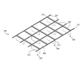
100101 FIG. I is a top plan view a ceiling system including. an overhead
suspended support.
grid and vertical baffles hung from the grid according to the present
disclosure;
100111 FIG. .2 is an enlarged top plan. detail from
[00I21 FIG. 3 tali .side elevation partial cross-sectional view from HO,. I;
[0013) FIG. 3A is an enlarged side elevation partial cross-sectional view from
FIG,
showing a first baffle mounting detail;
- 2 -
CA 02893049 2015-05-28
WO 2014/089516
PCT/US2013/073720
100141 FIG. 4 is an enlarged side elevation partial ctoss,sectional view from
FIG. I showing
a second baffle mounting detail;
100151 FIG. 5 is a top plan view of the vertical baffle of FIG. 1;
100161 FIG. 6 is a rear elevation view thereof;
100171 FIG. 6A is an enlarged detail taken from FIG. 6;
100181 FIG. 7 is a side elevation view of the vertical baffle of FIG. 5;
[00191 FIG. 7A is an enlarged detail taken from FIG. 7;
[00201 FIG. 8 is an enlarged mounting detail for mounting the vertical baffle
to a grid support
member of the support grid;
10021] FIG. 9A is a. side view showing a first step in a method. for mounting
the vertical
baffle from the support rid;
10022] FIG, 913 is a top plan view showing a second and third step in the
method for
mounting the vertical baffle from the support grid.;
[00231 FIG. 9C is a top plan view showing a fourth step in the method for
mounting the
vertical baffle from the support grid;
100241 FIG, 10 is a side elevation view taken from FIG. I showing multiple
vertical baffles
mounted. to the support grid;
10025] FIG. 11 is a side elevation view of an alternative embodiment of a
vertical baffle
having a lateral width capable of spanning across multiple grid openings of
the support grid;
100261 FIG. 12 is a perspective view of the baffle arrangement of FIGS. I and
10;
[00271 FIG, 13 is a perspective view of the alternative embodiment of the
vertical baffle of
FIG. II;
100281 FIG. 14 is a perspective view showing one mounting arrangement of
vertical baffles;
100291 FIG. 15 is a perspective view showing another mounting arrangement of
vertical
baffles in an alternating pattern;
10030] FIG. 16 is a perspective view showing a mounting arrangement of the
alternative
embodiment of the vertical baffle of FIG. 11;
[0031] FIG. 17 is a. side elevation view showing the vertical baffles mounted
in the support
grid with horizontal field tiles;
100321 FIG. 17A:is an enlarged detail taken from FIG. 17; and
100331 FIG, 18 is a perspective view showing the vertical baffles mounted in
the support grid
with horizontal field tiles.
100341 All drawings are schematic and not necessarily to Scale, Parts given a
reference
numerical designation in one figure may be considered to be the same pans
where they
- 3 -
CA 02893049 2015-05-28
WO 2014/089516
PCT/US2013/073720
appear in other figures without a numerical designation fir brevity unless
specifically labeled
with a different part number and described herein.
DETAILED DESCRIPTION OF THE EMBODIMENTS
100351 The features and benefits of the invention are illustrated and
described herein by
reference to exemplary embodiments. This description of exemplary embodiments
is
intended to be read in connection with the accompanying drawings, which are to
be
considered part of the entire written description. Accordingly, the disclosure
expressly
should not be limited to such exemplary embodiments illustrating some possible
non-Firniting
combination of features that may exist alone or in. other combinations of
features.
(0036j in the description of embodiments disclosed herein, any reference to
direction or
orientation is merely intended for convenience of description and is not
intended in any way
to limit the scope of the present invention. Relative terms such as "lower,"
"upper,"
"horizontal," "vertical,", "above," "below," "up," "down," "top" and "bottom"
as well as
derivative thereof (e.g., "horizontally," "downwardly," "upwardly," etc.)
Should be construed
to refer to the orientation as then described or as shown in the drawing under
discussion.
These relative terms are for convenience of description only and do not
require that the
apparatus be constructed or operated in a particular orientation. Terms such
as "attached,"
"affixed," "connected," "coupled," "interconnected," and similar refer to a
relationship
wherein structures are secured or attached to one another either directly or
indirectly through
Intervening structures, as well as both movable or rigid attachments or
relationships, unless
expressly described otherwise.
100371 FIG. 1 depicts an exemplary embodiment of a ceiling system 100
according to the
present disclosure. The ceiling system WO includes an overhead support grid
200 mountable
in a suspended manner from an overhead building support structure. Support
grid 200
includes a plurality intersecting longitudinal grid support members 202 and
lateral grid
support members 204. Longitudinal and lateral grid support members 202, 204
are elongated
in shape having a length greater than their respective length (e.g. at least
twice), and in
various embodiments lengths substantially greater than their widths (e.g. 3
times or more).
Longitudinal grid support member 202 may have a substantially greater length
than lateral
grid support member 204 and form "runners" which are maintained in a
substantially parallel
spaced. apart relationship by the lateral grid support members. The lateral
grid support
members 204 may be attached between adjacent (but spaced apart) longitudinal
grid support
members 202 at appropriate intervals using any suitable permanent or
detachable manner
- 4 -
CA 02893049 2015-05-28
WO 2014/089516
PCT/US2013/073720
employed in the art. The combination of interconnected longitudinal and
lateral grid support
members 202, 204 provides lateral stability to the support grid 200.
100381 In one embodiment, grid support members 202 and 204 may be horizontally
oriented
when installed. It will be appreciated, however, that other suitable mounted
orientations of
support mentbers 202, 204 such as angled or slanted (i.e. between 0 and 90
degrees to
horizontal). Accordingly, although support members 202, 204 may be described
in one
exemplary orientation herein as horizontal, the invention is not limited to
this orientation
alone and other orientations may be used,
100391 Longitudinal and lateral grid support members 202, 204 intersect:to
form an array of
grid openings 208 configured for insertion and mounting of the ceiling
vertical baffles 300.
In some embodiments, the grid support members 202, 204 may be arranged in an
orthogonal
pattern wherein support members intersect at right angles to form rectilinear
grid openings
208 such as squares or rectangles (in top plan view). The terminal ends of the
lateral grid
support members 204 may be configured to interlock with the transversely
oriented
longitudinal grid support members 202 at right angles to form the rectilinear
grid pattern in a
well-known manner in the art. Any suitable interlocking mechanism and
configuration may
be used, including for example without limitation interlocking tabs and slots,
brackets, clips,
etc. Accordingly, the present invention is not limited by the manner of
attachment used,
100401 In transverse cross section, longitudinal and lateral grid support
members 202, 204
may have a standard generally inverted T-shaped configuration when in an
installed position
suspended from an overhead ceiling support structure via an attachment
mechanism such as
without limitation fasteners, hangers, wires, cables, rods, struts, etc. Grid
support members
202, 204 may include a longitudinally-extending horizontal bottom flange 210,
a bulbous top
stiffening channel 220, and a vertical web 212 extending upwards from the
Mange to the
stiffening channel, The grid, support members 202, 204 each define a
respective longitudinal
axis LA.1. LA2 and axial directions. Web 212 may be centered between opposing
longitudinally extending edges 214 of flange 2.10 in one embodiment. Bottom
flange 210
defines upward facing bearing surfaces 2:01 configured and arranged to engage
a downward
facing bearing surlke 301 formed on baffle 300 Bearing surfaces 201 are
disposed on each,
side of web 212 and extend laterally outwards from the web to opposed edges
214 of the
bottom flange 210. In one embodiment, etlges. 214 may have aõ. slightly
enlarged bulbous
configuration in transverse cross-section (see, e.g, FIGS, 3A and 4), which
may assist with
eneaging mounting grooves in vertical baffle 300. Bottom flange 21.0 further
defines a.
bottom surface 206 facing downwards away from the flange and towards a room or
space
-5-.
CA 02893049 2015-05-28
WO 2014/089516
PCT/US2013/073720
below the support grid 200. Bottom surface .206 defines a horizontal reference
plane for the
overhead support grid .200. Vertical baffle 300 comprises upper and lower
sections 303, 3.05..
extending above and below the bottom flange 210 of grid, support members 202,
.204
respectively when. the baffles are fully mounted on the grid, as further
described herein.
10041] Grid support members 202, 204 may be .made of any suitable 'metallic or
non-metallic
materials structured to support the dead weight OT load Of baffles 300 without
undue
deflection. In some preferred but non-limiting embodiments, the grid support
members may
.made of metal including aluminum, titanium, steel, or other.
100421 FIGS, 5-7 (inclusive of all subparts) show vertical baffles 300 alone
in greater detail.
Each baffle 300 has a generally fiat tile or panel-like body including a top
302, bottom 304,
opposing lateral sides 306, 308, and opposing front and rear. faces 310, 312
respectively.
Each baffle defines a width WI, a height Ill, and thicknesses Ti and T2 (as
further described
herein). In one embodiment, the peripheral sides 306,, 308 may have straight
edges in
front/rear profile and form substantially parallel side surfaces extending
vertically (see, e.g.
FIG. 6).
10043-1 Front. and rear thces 310, 312 may each define .substantially flat
regular surfaces in.
side profile (see, e.g. FIG. 7), In other possible shapes that may be
provided, the front and
rear faces 310, 312 may have inenular surfaces including various undulating
patterns,
designs,. textures, .perforations, ridgesIvalleys, wavy raised features, or
other configurations
for aesthetic and/or acoustic (eR. sound reflection or dampening) purposes.
Accordingly,
front and rear faces 310. 312 are not limited to any particular surface
profile. Front and rear
faces 3.10, 312 of baffles 300 may be substantially parallel to each other in
some
embodiments (see, e.g. FIG. 7). In other possible embodiments, front and rear
faces 310, 312
may be angled or slanted in relation to each other to form baffles:having a
sloping face.
surfaces. The invention is therefore not limited to any of the foregoing
constructions.
10044] With continuing reference to FIGS. 5-7 inclusive, baffles 300 each
include a face
mounting groove 320 and at least one side mounting groove 322 each configured
for
engaging bottom flange 210 of grid support members 202, 204. In one
embodiment, two
opposing side mounting grooves 322 may be provided to support each lateral
side 306, 308
.from grid support .members. 202 or .204. In yet other possible embodiments,
two opposing
side mounting moves 322 may be provided without a face .mounting .groove 320,
in
premed. embodiments, both a face and two side mounting grooves 320, 322 may be
provided..lbr optimal support and square alignment of the vertical baffle 300
with respect to
the support grid 2.00 to create clean linear visuals.
- 6 -
CA 02893049 2015-05-28
WO 2014/089516
PCT/US2013/073720
11004.5l Face mounting groove 320 is formed into the rear face:3.12 of baffle
300 and extends
laterally across the face between lateral sides 306 and 108. In one
embodiment, face
mounting groove 320 extends completely across rear face 312 from side to side
and has a
width substantially coextensive with width WI of baffle 300. Face mounting
groove 320
may be oriented substantially .parallel to top and bottom 302, 304 of the
baffle 300.
100461 As best shown in FIG. 7A, the face mounting groove 320 extends .from
rear face 312
horizontally into baffle 300 towards .front face 310 and partially penetrates
the thickness 12
of the baffle upper section 303. Accordingly, face .mounting groove 320 has a
depth DI less
.than both thicknesses TI and T2 of baffle 300. In one embodiment, depth DI is
preferably
sufficient to receive an inserted portion of bottom flange 210 of lateral grid
support member
204 for securing baffle 300 to the support grid 200 in a. stable manner. Depth
Di may be
about one-half or less than the lateral width of bottom .flanges 210 measured -
between the
longitudinally extending opposed edges 214 of the bottom flange (see, e.g.
FIG. 4 and 7A).
Face mounting groove 320 opens in a horizontal rearward direction (defined as
a direction
towards rear face 312).
00471 With continuing reference to -FIGS. 5-7 inclusive, the -ffice mounting
groove 3.20 may
be considered to divide the vertical baffle 300 into an upper section 303
lying above groove
320 and a lower section 305 lying below the groove. Upper section 303
generally is
positioned or located above bottom flange 210 of grid support members 202,
204, and
therefore may not be visible to an observer from below the support grid 300
when the baffles
and horizontal field ceiling tiles 400 (if provided) are fully mounted (see,
en. -FIG, 18).
Conversely, lower section 305 generally is positioned or located below bottom
flange 210 of
grid support members 202, 204, and may generally be visible to an observer
from below the
support grid 300 when the baffles and -horizontal field ceiling tiles 400 (if
provided) are fully
mounted..
100481 Referring also to FIGS. 3A. and 4, upper section 303 of baffle 300 may
have a vertical
height which is approximately coextensive with or less than the vertical
height of longitudinal
and lateral grid support members 202, 204, In one exemplary embodiment, upper
section 303
has a vertical height tall enough to abuttingly engage at least a portion of
the top stiffening
channel 220 of grid support members 2.02., 2,04 for enhancing lateral
stability of the mounted
vertical baffles 300, The IdSible lower .section 305 of baffles 300 which
extends below the
grid support members 202, 204 may have any suitable height. desired depending
on the extent
of the -baffle which is to be visible and project into the occupied space
beneath the support
-7-.
CA 02893049 2015-05-28
WO 2014/089516
PCT/US2013/073720
mid 200. The height selected may depend on factors. such as .ornamental
appearance,
'acoustic performance ,(e.g. 'sound dampening or reflections), available head
space, and others.
100491 In one embodiment, upper section 303 of baffles 300 may have a
thickness 12 that is
less than the thickness Ti of lower section 305 (both measured between front
and rear faces
310, 312). This provides the "stepped" rear face 312 in side profile shown in
FIGS. 4 and 7
wherein the rear face or surface of upper section 303 is horizontally offset
from and lies in a
.diffeeent vertical plane than the rear face or surface of lower section 305.
Advantageously,
.this offSet rear face 312 configuration allows at least part of the visible
baffle lower section
305 .to extend horizontally/laterally beneath and conceal bottom flange 210 of
grid, support
members 202., 204. When adjacent horizontal field tiles 400 (if provided.) are
mounted to
support grid 200 as shown in FIG. I7A, the grid support members 202, 204 may
then be
entirely concealed by the visible lower sections 305 of baffle 300 and field
tiles 400 if
desired,
[00501 'Referring to FIGS. 5-7 inclusive side mounting grooves 322 are each
formed into a
respective Side 306,i308 of baffle 300 and extend between front and rear
.faces.310,. 312 of the
baffle. In one embodimem, each side mounting groove 322 extends completely
across the
sides 306, 308 from front face 310 to rear face 312 from side to side having a
width
substantially coextensive with the thickness T2 of -tipper section 303 of the
baffle 300 (best
shown in FIG. 7A), The side mounting- grooves 322 may there .fore intersect
both front and
rear faces 310, 312 in some embodiments. Side mounting grooves 322 may be
oriented
substantially parallel to top and bottom 302, 304 of the baffle 300,
10051) With continuing reference to 'FIGS. 5-7 inclusive, the side mounting
grooves 322
horizontally extend from lateral sides 306, 308 inwards towards a. vertical
centerline of the
baffle 300 (lying midway 'between sides 306 and. Win the direction parallel to
width WI.
Side mounting grooves 322 partially penetrate the baffle upper section 303 in
one
embodiment; each groove 322 having a depth D2 less than width WI of baffle
300. In one
embodiment, depth D2 is pretrably sufficient to receive an inserted portion of
bottom flange
210 of grid longitudinal support members 202 for securing baffle 300 to the
support grid 200
in a stable 'manner. Depth D2 may he about one-half or less than the lateral
width of bottom
.flanges .210 .measured between the longitudinally extending opposed edges
2.14 of the bottom.
flange (see., e.g. and .64
Side mounting grooves 3.22 open outwards in a horizontal
or lateral direction from baffle 300 (defined as a direction perpendicular to
lateral sides 306
and 308)..
- 8 -
CA 02893049 2015-05-28
WO 2014/089516
PCT/US2013/073720
100521 Wheti longitudinal grid support members 202 and lateral grid support
members 204
are fully mounted, the bottom surfaces 206=of flanges 210 will substantially
lie on the same
horizontal plane. Accordingly, in an exemplary non-limiting embodiment, face
mounting
grooves 320 and side mounting grooves 322 may substantially lie on that same
horizontal
plane and intersect each other at two opposing corners of the rear face 3.12
of each vertical
baffle 300 (see, e.g. Fl.C1S. 6õ 7, 6A, and 7.A.). This allows the side
mounting grooves 312 to
engage the bottom :flanges 210 of two opposing and laterally spaced
longitudinal grid support
members 202 and .the face mounting groove 310 of baffle 300 to engage the
bottom flange
210 of a lateral grid support member 204 which spans between the two
longitudinal grid
support members (see FIG. 1). In this embodiment, the face and side mounting
grooves 320,
322 and bottom flanges 210 of grid support members 202, 204 all substantially
lie or fall on
the same common horizontal mounting plane.
100531 Face and side mounting grooves 320, 322 are configured for removably
receiving
portions of the bottom flange 210 of grid support members 202, 204 to mount
vertical baffles'
300 to support grid .200. Preferably, face and side mounting grooves 3.20,
3.2.2 have a height
slightly larger than the thickness (vertical) of bottom flange 210 to allow
the flange to be
inserted., but not so large to allow excessive vertical play of the flange in
the grooves to
prevent wobbling of the baffles 300 particularly under indoor air currents
induced by :forced
air I-1VAC theatine ventilating and air conditioning) systems or
ingress/egress dra.fls. Each of
the face and side mounting grooves 320, 322 define downward facing bearing
surfaces 30.1
which engage upward facing bearing surfaces 201 on bottom flanges 210 Which
support the
baffles 300 from the support grid 200. In one embodiment, the bearing surfaces
301 formed
in face and side mounting grooves 320, 3.2.2 are contiguous and .fall on the
same horizontal
plane to match bottom flanges 210 of grid support members' 202, :204 which
engage these
support surfaces and similarly fell on the same horizontal plane.
1.00541 Vertical baffles 300 may be formed of any suitable material, including
without
limitation mineral fiber board., fiberglass, jute fiber, metals, polymers,
wood, or other. Face
and side mounting grooves 320, 322 may be formed by any suitable fabrication
method,
including for example without limitation routing, cutting, molding, or others.
100551 .A method for mounting a vertical baffle 300 to .3 support grid. 200 of
ceiling system.
100 will now be described, with primary reference to FIGS.. 9A-C Which shows
sequential
mourning steps.
100561 The method includes first providing an overhead support grid .2.00
which has already
been mounted and suspended from an overhead building support structure.
Vertical baffle
- 9 -
CA 02893049 2015-05-28
WO 2014/089516
PCT/US2013/073720
300 is:positioned below support grid. 200 beneath one of the grid.
openings.:20.8.- The vertical
baffle 300 is then raised upwards ortially through the grid opening 208 until.
side mourning
grooves 322 are horizontally aligned, with bottom flanges 2.10 of longitudinal
grid support
members 202 (see, e.g. circled Step I, FIG. 9A and FIG. 9B). Preferably,
vertical baffle 300
is vertically oriented and obliquely positioned in grid opening 208 with
respect to
longitudinal and lateral grid support members 202., 204 when raised., in the
present non-
limiting embodiment, the width W of the -vertical baffle is selected to be
slightly wider than
.the lateral width measured between opposing edges 214 of the longitudinal
grid support
members 202 which border grid opening .208 for retaining vertical baffle 300
in the support
grid 200 via baffle side mounting grooves 322,
100571 With vertical baffle 300 in the foregoing oblique orientation, a. first
one of the lateral
sides 306, 308 of vertical baffle 300 (e.g. side 308 in this non-limiting
example as shown) is
moved laterally into contact with one of the longitudinal grid support members
202 ("see, e.g.
circled. Step 2, FIG. 9B). In one embodiment, this lateral motion may be
substantially in a
linear direction of side 308 towards the grid support member 202_ The side
mounting groove
322 of lateral side 308 is then engaged with bottom flange 210 of the
longitudinal grid
support member .202, as further shown in FIG. 8,
100581 As further shown in FIG. 913, the vertical baffle 300 is -then rotated
(clockwise in this
figure about the vertical centerline of the baffle) while substantially
maintaining engagement
between side 308 and longitudinal grid support member 202 above and further
maintaining
the horizontal alignment between the bottom flanges 210 of the opposing
longitudinal grid
support members 202 and both side mounting grooves 322 of the baffle lateral
sides 306 and
308. The remaining second one of the lateral sides 306 (in this example) is
then moved
laterally into contact with the remaining longitudinal grid support member 202
engaging side
mounting groove 322 with the bottom flange 210 of the grid support member, as
shown (see,
e.g. circled Step 3), In One embodiment, this lateral motion may be
substantially angular in
direction in moving side 306 towards the grid support member 2.02 as .the
vertical baffle is
rotated. Vertical baffle 300 is rotated until the baffle is substantially
parallel in orientation (in
the top plan view shown) with respect to the lateral grid support member 204
on which the
baffle will be further mounted (see, :e.g. HQ.: 9C). Vertical baffle 300 is
now also oriented
perpendicular to both longitudinal grid support members 202 on either side.
Both mounting
grooves 322 on lateral sides 306, 308 are now fully engaged with the opposing
longitudinal
grid support members 202. The vertical baffle 300 is fully supported by the
bottom -flanges
-10-
CA 02893049 2015-05-28
WO 2014/089516
PCT/US2013/073720
210 of longitudinal grid .support members 202 such that an installer may
release the baffle if
desired without providing Supplemental. support.
100591 It will be appreciated that in some variations of the forgoing mounting
method
described thus far, the vertical baffle 300 may Apply be rotated once
obliquely positioned in
grid opening 208 to simultaneously engage both lateral sides 306, 308 with a
respective
longitudinal grid support member 202, in lieu of one lateral side at a time in
the sequential
manner described above. Either installation approach is acceptable.
[00601 With the vertical baffle 300 now oriented orthogonally with respect to
grid support
members 202, 204 as shown in FIG. 9C, the vertical baffle 300 is slidably
moved along
longitudinal grid support members 202 towards lateral grid support member 204
in an axial
direction parallel to longitudinal axis LAI (see also FIG. Vertical
baffle 300 is slid until
face mounting groove 320 engages bottom flange 108 on the lateral grid support
member 204
thcing toward rear face 312 of the baffle (see, e.g. circled Step 4, FIG.
9C.). The vertical
baffle 300 is now fully mounted and engaged on three adjoining sides with
support grid 200,
as shown in FIG. 1. Vertical baffle 300 is simultaneously engaged via thee and
side
mounting grooves 320, 322 with both lateral grid support members 204 and one
of the
longitudinal grid support members 202 bordering the grid opening 208. Assuming
that the
support grip 200 has been squarely installed, mounting of additional vertical
baffles 300 in
other grid openings 208 will ensure that the baffles are properly positioned
and registered to
provide a clean and orthogonal linear visual.
[00611 FIG, 10 shows a rear elevation view of the vertical baffle 300
installation taken from
Fla I along section line "X." Three vertical baffles 300 are shown installed
in three
adjacent and adjoining grid openings 208 in the support grid 200. FIG. 14
shows an
exemplary non-limiting arrangement of vertical baffles 300 mounted to support
grid 200 in a
similar manner to that shown in FIG. 10 having a baffle installed in each
available grid
opening 208. FIG. 12 shows this arrangement of venical baffles 300 disembodied
from the
support grid 200 to better show the relation of the vertical baffles alone in
this mounting
scenario. A vertical joint is visible adjacent vertical baffles 300 in each
linear row as shown.
[00621 FIG. 15 shows an alternative arrangement in which vertical baffles 300
are installed in
a staggered and alternating arrangement skipping a :grid opening 208 in each
lateral row (i.e.
between longitudinal grid support members 202). A grid opening is hence also
skipped in
each longitudinal row (i.e. between lateral grid support members 204. It will
be evident that
numerous arrangements and arrays of vertical baffles 300 are possible and the
invention is
not limited to any particular arrangement.
- 11 -
CA 02893049 2015-05-28
WO 2014/089516
PCT/US2013/073720
[0063i In the ceiling 'systems: 100 described thus far, the vertical baffles
300 have been
configured and dimensioned to fit within a single ijid. opening 208. This
creates a series of
interrupted front faces 310 between baffles 300 with vertical joints
tberebetween positioned
near and beneath each longitudinal grid support. member 202. FIGS. 11, 13, and
16 show an
alternative configuration of a vertical baffle 350 having a unitary structure
which is designed
to span across two or more adjacent grid openings 208 (and three or more
longitudinal grid
support members 202). This creates a continuous front face 310 for a certain
width between
at least two or more longitudinal grid support members .202 and grid openings
.208;
100641 With continuing reference to FIGS. 1.1, 13. and. 16, vertical baffle
350 has a lateral
width (identified as WI in FIG. 6) larger than the corresponding lateral width
or opening
measured between opposing parallel longitudinal grid support members 202 (best
shown in
FIG, 16). The baffle upper section 303 is interrupted by one or more laterally
spaced apart
grid mounting gaps 352 each sized to receive at least partially therein a
longitudinal grid
support member 202. The gaps 352 have a lateral width preferably slightly
larger than the
lateral width of bottom flanges
210 of grid support members 202 for inserting the flanges into
the gaps. The gaps 352 are further wide enough to allow the vertical baffle
350 to be
positioned obliquely within two or more grid openings 208 and then rotated
into the fully
mounted position (see FIG. 16) in a similar manner to mounting. vertical
baffle 300 as
described in the foregoing method. .In the non-limiting embodiment Shown,
there are two
vertical grid mounting gaps 352 and the vertical baffle 350 spans across three
grid openings
208. Other suitable lateral widths and numbers of gaps 352 may be provided in
other
configurations and variations of the vertical baffle 350 depending on the
width of vertical
baffle 35 provided, .
100651 In non-limiting exemplary embodiments, vertical baffle 350 may be
similar in other
construction details to vertical baffle 300 including the provision of face
and side mounting
grooves 320, 322. In some embodiment, side mounting grooves 322 may also be
formed
within the grid mounting gaps 352 in the baffle upper section 103 to thither
support the
vertical baffle 350. in other embodiments, the side mounting grooves 322 may
only be
'provided at the lateral sides 306, 308.
100661 FIGS. 17 and. IS show an exemplary continuous version of ceiling system
100
including vertical baffles 300 and horizontal field tiles 400 -Which fill the
voids in grid
openings 208 between the vertical baffles and grid support members 202, 204,
FIG, 17A is a
cross-section detail of the joint formed between the field tiles 400 and a
vertical baffle 300 at
a lateral grid support member 204. The field tiles 400 may be abutted against
vertical baffles
- 12-
CA 02893049 2015-05-28
WO 2014/089516
PCT/US2013/073720
300 and supported .from the support grid 200 in any suitable manner used in
the art.
Horizontal field tiles 400 may have any suitable lateral edge profile,
including square lay-in
edges, tegadar edges, or others.. In some embodiments, the lateral edges may
rest on top of
bottom flanges 210 of the grid support members 202, 204 when mounted in a
known manner.
Clips or brackets (not shown) may further be used to mount the field tiles 400
to grid support
members 202, 204 in certain embodiments.
[0067) It will be appreciated that in some embodiments having an open ceiling
concept or
system, vertical baffles 300 or 350 may be used alone and mounted on support
ffid 200
without horizontal field tiles 400. Accordingly, the invention is not limited
in any manner to
either the use or absence of horizontal field tiles 400 in the ceiling system
100.
10068] While the foregoing description and drawings represent exemplary
embodiments of
the .present disclosure, it will be understood that various additions,
modifications and
substitutions may be made therein without departing from the spirit and scope
and range of
equivalents of the accompanying claims, in particular, it will be clear to
those Skilled in the
art that the present invention may be embodied in other forms, structures,
arrangements,
proportions, sizes, and with other elements, materials, and components,
without departing
from the spirit or essential characteristics thereof. In addition, numerous
variations in the
methods/processes described herein may be made within the scope of the present
disclosure.
One skilled in the art will further appreciate that the embodiments may be
used with many
modifications of structure, arrangement, proportions, sizes, materials, and
components and
otherwise, used in the practice of .the disclosure, which are particularly
adapted to specific
environments and operative requirements without departing from the principles
described
herein. The presently disclosed embodiments are therefore to be considered. in
all respects as
illustrative and not restrictive. The appended. claims should be construed
broadly, to include
other variants and embodiments of the disclosure, which may be made by those
skilled in the
art without departing from the scope and range of equivalents.
-13-