Note: Descriptions are shown in the official language in which they were submitted.
CA 02893073 2015-05-29
54699-40
DESCRIPTION
"A DISPENSER OF CRYOGENIC SUBSTANCES, AND A PROCESS
FOR DISPENSING THE CRYOGENTIC SUBSTANCES"
FIELD OF INVENTION
The present invention relates to a dispenser of cryogenic substances and a
method for
dispensing them. The method and dispenser are applicable in the treatment of
disorders or
illnesses of the skin. In particular, the dispenser, particularly of the spray
type, can be used in
the field of dermatology for treatment of various pathologies/imperfections of
the skin, for
example for the topical treatment of verrucas, seborrheic keratosis, skin
tags, freckles,
. 10 cutaneous formations, unaesthetic skin conditions, etc.
STATE OF THE ART
As is known, the use of cryogenics is in continuous expansion in applications
in the medical
field (for example in cryosurgery and in cryo-conservation). Of particular
interest for the
following description, is the use of cryogenics in the medical field, in
particular in the
dermatological field.
In the dermatological field, cryogenic substances (for example liquid
nitrogen) widely amply
used, as, differently to classic surgical interventions, they usually require
no anaesthetic, do
not usually create scar tissue, do not require problematic dressings nor long
periods of
convalescence after treatments.
Of particular interest for the following description are spray devices for
dispensing cryogenic
substances and the topical treatment of skin imperfections.
A first example, described in document WO 2007/028975, concerns a dispensing
device of
cryogenic substances for treatment of epidermis tissue. The device is
constituted by a can on
which a dispensing system is arranged, for enabling emission of the cryogenic
fluid through a
tubular extension which terminates with an applicator proper: the applicators
are circular and
1
CA 02893073 2015-05-29
54699-40
can exhibit different diameters according to the dimensions of the lesion to
be treated. The
applicators are, further, removably associated to the device in such a way as
to be replaceable.
A second example, described in document US 2010/042087, also concerns a
cryogenic device
for treatment of skin diseases. The device comprises a can exhibiting a
dispensing button on
which a dispensing tube is mounted which, on the distal end thereof, exhibits
an applicator.
The applicator exhibits an engaging portion, able to receive a dispensing
cannula, and a
truncoconical application section associated to the dispensing cannula at
which at least a
dispensing piercing for expulsion of cryogenic gases is present.
The second example too specifies the presence of removable applicators, having
a different
shape and section for treating lesions of different natures and sizes, and
made of transparent
material for enabling viewing the zone to be treated.
A third example, described in document GB 1 163 573, concerns a cryogenic
device for
treatment of skin disturbances of the skin in which a substance is dispensed
from a spray can
by means of a dispensing channel and directed at the zone to be treated. In
particular, the
document describes a truncoconical applicator in which the distal portion from
the application
point functions as an escape for the pressurized gas. The third example
specifies, similarly to
what is described in the above examples, that the device can receive
applicators of different
dimensions or be used in the inverse shape thereof in such a way as to apply
the fluid at the
larger diameter of the truncoconical shape. Differently to the above-cited
documents, in the
third example no reference is made to the possibility of using applicators
made of a
transparent material.
The devices described in the above examples enable the user to have a good
control over the
dispensing of the cryogenic substance in outlet from the can thanks to the use
of the
applicators: the applicators enable using the can at a correct distance from
the zone to be
treated and dispensing the cryogenic substance at the zone. Further, the
possibility of
mounting various types of applicators, having a diversified shape and/or
dimension,
guarantees the above-described devices a good flexibility of use.
2
CA 02893073 2015-05-29
54699-40
However, the above-described devices are not free of drawbacks and
limitations. In order
better to fully understand the drawbacks of the devices described above, it is
useful to specify
that the cryogenic treatments require particular precautions given the nature
of the substance
with which the treatment is carried out; these substances can in fact cause
burns, or, if
dispensed on unsuitable zones for treatment, cause grave lesions.
The devices briefly analysed in the foregoing do not exhibit a safety system
able to effectively
prevent an accidental dispensing of the cryogenic substance.
AIM OF THE INVENTION
The aim of the present invention is substantially to obviate at least one of
the drawbacks
and/or limitation of the prior art.
A first objective of the invention is to provide a method and a dispenser of
cryogenic
substances of cryogenic substances exhibiting at least a safety system able to
prevent
accidental dispensing of cryogenic substance.
A further main aim of the invention is to provide a method and a dispenser of
cryogenic
substances that enable an excellent control of the quantity of substance to be
dispensed as well
as an excellent dispensing precision.
A further aim of the invention is to provide a method and a dispenser of
cryogenic substances
exhibiting a high flexibility of use, in particular being usable for various
topical treatments.
A further aim of the invention is to provide a dispenser of cryogenic
substances composed of
a minimum number of components such that the dispenser is simple to realise,
easy to use and
assemble and constructed with a specific structure that optimises the
effectiveness of the
treatment.
A further aim of the present invention is to provide a dispenser of cryogenic
substances the
components of which exhibit a production and assembly cost that is smaller so
that the
dispenser is economical.
3
CA 02893073 2015-05-29
54699-40
One or more of the above-described aims, which will more fully emerge during
the course of
the following are substantially attained by a method and a dispenser of
cryogenic substances
as described herein.
SUMMARY
Aspects of the invention are described in the following.
A first aspect relates to a dispenser (1) of cryogenic substances (C),
comprising:
at least a pressurised container (2) configured such as to contain a
predetermined quantity of
cryogenic substance (C), the container (2) exhibiting at least an opening (2a)
suitable for
enabling exit of the cryogenic substance (C) along an expulsion direction (E),
the container
(2) comprising a valve (3) active at the opening (2a) and configured such as
to be arranged in
a normally closed condition in which it prevents the exit of the cryogenic
substance (C) from
the opening (2a), the valve (3) being further configured such as to be
arranged, following an
activating operation thereof, in a passage condition in which the valve (3)
enables exit of the
cryogenic substance (C),
at least a coupling element (4) comprising a first engaging portion (10) able
to stably constrain
the coupling element (4) to the container (2) substantially at the opening
(2a), the coupling
element (4) comprising a second engaging portion (11) emerging from the first
engaging
portion (10) distancingly with respect thereto, the second engaging portion
(11) comprising at
least a blocking portion (7) and at least a passage seating (8) angularly
offset to one another
with respect to an axis (A) that is substantially parallel to the expulsion
direction (E),
at least an activating element (5) cooperating with the second engaging
portion (11) of the
coupling element (4) such that the coupling element is interposed between the
container (2)
and the activating element (5), the activating element (5) comprising a
dispensing conduit (6)
in fluid communication with the opening (2a) of the container (2) and
configured such as to
.. enable emission of the cryogenic substance (C) towards the external
environment, the
activating element (5) further comprising an active portion (9) able to
cooperate with the
blocking portion (7) and the passage seating (8) of the coupling element (4),
4
CA 02893073 2015-05-29
54699-40
and wherein the activating element (5) is configured so as to define, in
cooperation with the
coupling element (4) at least following operating conditions:
at least a dispensing condition in which the active portion (9) of the
activating element (5) is
at the passage seating (8), the activating element (5), in the dispensing
condition, being
translatable along a sliding direction (S) nearingly to the container (2), the
activating element
(5), following the nearing along the sliding direction (S) towards the
container (2), being
configured such as to arrange the valve (3) in the passage condition and
consequently
enabling exit of at least a part of the cryogenic substance (C) from the
opening (2a),
at least a safety condition in which a lower appendage (9a) of the activating
element (5) is
located at the at least a blocking portion (7) of the coupling element (4),
the activating element
(5), in the safety condition, being stably blocked to the coupling element (4)
preventing
relative rotations and axial slidings of the activating element (5) with
respect to the coupling
element (4),
at least an intermediate condition in which the activating element (5) is
mobile relatively to
.. the coupling element (4) by rotation about the axis (A) substantially
parallel to the expulsion
direction (E), the activating element (5), in the intermediate condition,
being mobile from a
dispensing condition to a safety condition and vice versa,
the activating element (5) is configured such as to elastically deform,
following application of
an external stress (F), such as to enable, at least in the safety condition,
the decoupling
between the lower appendage (9a) of the activating element (5) and the
blocking portion (7) of
the coupling element (4), the activating element (5), following the
application of the external
stress (F), being arrangeable in the intermediate condition and consequently
being able to pass
from the safety condition to at least a dispensing condition.
In a second aspect according to the 1st aspect, when in the safety condition
the activating
element is not mobile relative to the coupling element (4).
In a 3rd aspect according to any one of the preceding aspects the activating
element (5)
comprises a body (5c) having at least a thrust portion (5d) located at an
external lateral wall
5
CA 02893073 2015-05-29
=
54699-40
(5e) of the body (Sc), the thrust portion (5d) being configured such as to
receive the external
stress (F) directed transversally to the expulsion direction (E), the thrust
portion (5d),
following the application of the external stress (F), being configured such as
to elastically
deform at least a portion of the body (5c) in such a way as to enable the
distancing of the
active portion (9) of the activating element (5) with respect to the blocking
portion (7) of the
coupling element (4) such as to enable decoupling thereof.
In a 4th aspect according to the preceding aspect the thrust portion (5d) is
angularly offset
relative to the active portion (9) with respect to the axis (A), in particular
being offset by 90
with respect to the active portion (9).
In a 5th aspect according to aspects 3 or 4, the body (Sc) comprises two
thrust portions (5d)
located symmetrically to one another with respect to the axis (A)
substantially parallel to the
expulsion direction (E).
In a 6th aspect according to any one of the preceding aspect, the coupling
element exhibits a
shape substantially having a cylindrical symmetry about the expulsion
direction (E).
In a 7th aspect according to any one of the preceding aspects the first
engaging portion (10) is
stably coupled with an engaging portion (2b) of the container (2) positioned
at the opening
(2a), the second engaging portion (11) being configured such as to stably
constrain the
activating element (5) to the coupling element (4), the second engaging
portion (11) of the
coupling element (4) being connected to the first engaging portion (10) of the
coupling
element (4) and emerging distancingly with respect thereto.
In an 8th aspect according to any one of the preceding aspects the second
engaging portion
(11) of the coupling element (4) comprise the blocking portion (7), which
exhibits at least a
projection (15) defining at least a radial intersection portion (13) and a
support portion (17).
In a 9th aspect according to any one of aspects from 3 to 8, the body (Sc) of
the activating
element (5) defines a housing compartment (5a) delimited by an internal
lateral wall (5b) and
containing at least a part of the second engaging portion (11) of the coupling
element (4), the
active portion (9) of the activating element (5) comprising at least a
projection (12) emerging
6
CA 02893073 2015-05-29
54699-40
from the internal lateral wall (5b) of the housing compartment (5a) nearingly
to the coupling
element (4), the projection (12) of the activating element (5) defining at
least a radial
intersection portion (13) and an axial intersection portion (14).
In a 10th aspect according to the preceding aspect, the the radial
intersection portion (13) and
the axial intersection portion (14) of the activating element (5), during the
safety condition,
are abutted respectively to the radial intersection portion (16) and the
support portion (17) of
the coupling element (4), in the safety condition the radial intersection
portion (16) and the
support portion (17) of the coupling element (4) being configured such as
respectively to
prevent the rotation and translation of the activating element (5).
In an I I th aspect according to the preceding aspect the radial intersection
portion (16) of the
coupling element (4) defines a radial undercut with respect to the radial
intersection portion
(13) of the activating element (5), the radial intersection portion (13) of
the activating element
(5), during the safety condition, being abutted to the radial intersection
portion (16) of the
coupling clement (4) and blocked in movement with respect thereto.
In a 12th aspect according to any one of aspects from 9 to 11, the axial
intersection portion
(14) of the activating element (5) is abutted to the support portion (17) of
the coupling
element (4), at least in the safety condition.
In a 13th aspect according to any one of aspects from 9 to 12, the axial
intersection portion
(14) of the activating element (5) is abutted to the support portion (17) of
the coupling
.. element (4) in the safety condition and in the intermediate condition.
In a 14th aspect according to any one of aspects from 8 to 13, the support
portion (17) of the
coupling element defines an axial undercut able to prevent the activating
element (5), at least
in the safety condition, from translating along the expulsion direction (E)
nearingly to the
container (2).
In a 15th aspect according to any one of the preceding aspects, the passage
seating (8) of the
coupling element (4) is arranged on the second engaging portion (11) thereof
and extends
substantially parallel to the expulsion direction (E), the passage seating (8)
being angularly
7
CA 02893073.2015-05-29
54699-40
offset with respect to the blocking portion (7) of the coupling element (4)
with respect to the
expulsion direction (E).
In a 16th aspect according to any one of aspects from 9 to 15, the passage
seating (8) being
configured such as to enable passage of the axial intersection portion (14) of
the activating
element (5), during the dispensing condition, and therefore the sliding of the
activating
element (5) nearingly to the container (2).
In a 17th aspect according to any one of the preceding aspects, the coupling
element (4)
comprises two blocking portions (7) located symmetrically to one another with
respect to the
expulsion direction (E), and wherein the coupling element further comprises
(4) two passage
seatings (8), also located symmetrically to one another with respect to the
expulsion direction
(E), the blocking portion (7) and the passage seatings (8) being angularly
offset with respect
to one another with respect to the expulsion direction (E), in particular
being offset by 90 to
one another.
In an 18th aspect according to any one of aspects from 8 to 17, the second
engaging portion
(11) of the coupling element (4) comprises at least a lateral wall (18)
extending substantially
parallel to the expulsion direction (E), the radial intersection portion (16)
of the coupling
element (4) emerging radially from the lateral wall (18) towards the internal
lateral wall (5b)
of the housing compartment (5a), and wherein the support portion (17) of the
coupling
element (4) is defined by at least a portion of the free end surface of the
lateral wall (18)
.. located on an opposite side with respect to the first engaging portion (10)
of the coupling
element (4).
In a 19th aspect according to any one of aspects from 9 to 18, the projection
(12) of the
activating element (5) comprises at least a rib (19) emerging substantially
parallel to the
internal lateral wall (5b) of the housing compartment (5a) nearingly to the
coupling element
(4), the rib (19) defining the radial intersection portion (14) and the
support portion (15) of the
activating element (5).
In a 20th aspect according to aspects 18 or 19, the lateral wall (18) of the
coupling element (4)
exhibits a substantially hollow cylindrical shape, in particular concentric to
the expulsion
8
CA 02893073 2015-05-29
54699-40
direction (E), and wherein the activating element (5) comprises a first
engaging portion (20)
constrained to the second engaging portion (11) of the coupling element (4),
the engaging
portion (20) of the activating element (5) comprising at least an abutment
(21) emerging from
the internal lateral wall (5b) of the housing compartment (5a) and constrained
to the inside of
the lateral wall (18) of the coupling element, the lateral wall (18) of the
coupling element (4)
being configured so as to enable constraining the activating element (5) and
the centring
thereof on the coupling element (4).
In a 21st aspect according to the preceding aspect the engaging portion (20)
of the activating
element (5) is at least partially complementarily shaped to the lateral wall
(18) of the coupling
element (4).
In a 22nd aspect according to any one of the preceding aspects the dispensing
conduit (6) of
the activating element (5) is arranged internally of the engaging portion (20)
thereof, the
dispensing conduit (6) being configured so as to arrange the valve (3) in the
passage
condition, during the translation of the activating element (5) along the
expulsion direction
(E).
In a 23rd aspect according to any one of the preceding aspects, the activating
element (5) is
unremovably constrained to the coupling element (4).
In a 24th aspect according to any one of the preceding aspects, the container
(2) during the
dispensing condition, is configured such as to dispense only a predetermined
discrete quantity
of cryogenic substance (C) less than the total quantity of cryogenic substance
(C) present
internally of the container (2).
In a 25th aspect according to the preceding aspect, the container (2)
comprises comprises a
general chamber (2c) configured such as to contain a predetermined quantity of
cryogenic
substance (C), the container (2) further comprising a pre-chamber (2d)
exhibiting at least an
inlet (22) for setting the general chamber (2c) in fluid communication with
the pre-chamber
(2d), the pre-chamber (2d) further exhibits at least an outlet (23) for
setting the pre-chamber
(2d) in fluid communication with the opening (2a) of the container (2), the
container (2)
comprising at least a valve (24) operatively active on the inlet (22) and on
the outlet (23) of
9
CA 02893073 2015-05-29
54699-40
the pre-chamber (2d), the valve (24), in the dispensing condition, being
configured such as to
set the pre-chamber (2d) in fluid communication with the opening (2a) of the
container (2)
and to prevent the passage of fluid between the general chamber (2c) and the
inlet (22), the
valve (24) of the container (2), in the dispensing condition, being configured
such as to enable
emission of the predetermined quantity of cryogenic substance (C) present in
the pre-chamber
(2d) of the opening (2a) of the container (2), and wherein the valve (24), in
the safety
condition and/or in the intermediate condition, is configured such as to set
in fluid
communication the pre-chamber (2d) with the general chamber (2c) and prevent
the passage
of fluid between the pre-chamber (2d) and the opening (2a) of the container
(2).
In a 26th aspect according to the preceding aspect, the pre-chamber (2d)
exhibits a smaller
volume that the volume of the general chamber (2c) and the ratio between the
volume of the
general chamber (2c) and the volume of the pre-chamber (2d) is greater than 2,
in particular
greater than 3, still more in particular greater than 4.
In a 27th aspect according to any one of the preceding aspect, the dispenser
comprises at least
an applicator (25) having a body (26) extending along a prevalent development
direction
between a first and a second end (27, 28), the applicator (25) being removably
engaged, at the
first end (27), to the activating element (5) and emerging from the external
lateral wall (5e)
thereof in an exiting direction with respect to the housing compartment (5a)
of the activating
element (5), and wherein the applicator (25) exhibits a through-opening (29)
extending
internally of all the body (26) from the first end (27) to the second end
(28), the dispensing
conduit (6) of the activating element (5) being in fluid communication with
the opening (29)
of the applicator (25), the applicator (25), in the dispensing condition,
being configured such
as to guide the cryogenic substance (C) arriving from the container (2)
towards the outside
environment.
In a 28th aspect according to the preceding aspect, the opening (29) defines,
at the first and
second ends (27, 28), respectively a first and a second passage opening (30,
31), the first
passage opening (30) defining a passage area that is smaller than the passage
area defined by
the second passage opening (31).
CA 02893073 2015-05-29
54699-40
In a 29th aspect according to the 27 and 28th aspect the opening (29) exhibits
a shape having
a cylindrical symmetry about an axis that is substantially parallel to the
prevalent development
direction of the applicator (25), in particular the opening (29) exhibiting a
truncoconical shape
having a growing passage section from the first end (27) in the direction of
the second end
(28).
In a 30th aspect according to aspects 27, 28 or 29, the applicator (25) is
removably engaged to
the activating element (5).
In a 31st aspect according to any one of aspects from 27 to 30, the applicator
(25) is at least in
part realised in a transparent material, in particular the applicator (25) is
totally made of a
transparent material.
In a 32nd aspect according to any one of aspects from 27 to 31, the applicator
25 is at least
partly realised in a plastic material, by way of example the applicator (25)
being made of at
least one of the following materials: polypropylene, polyethylene, PVC.
A 33rd aspect relates to a method for dispensing cryogenic substances (C)
comprising
following steps:
predisposing at least a pressurised container (2) configured such as to
contain a predetermined
quantity of cryogenic substance (C), the container (2) exhibiting at least an
opening (2a)
enabling exit of the cryogenic substance (C) along an expulsion direction (E),
the container
(2) comprising a valve (3) active at the opening (2a) and configured such as
to be arranged in
a normally closed condition in which it obstructs exit of the cryogenic
substance (C) from the
opening (2a), the valve (3) being further configured such as to be arranged,
following an
activating operation thereof, in a passage condition in which the valve (3)
enables exit of the
cryogenic substance (C),
predisposing at least a coupling element (4) comprising a first engaging
portion (10) able to
stably constrain the coupling element (4) to the container (2) substantially
at the opening (2a),
the coupling element (4) comprising a second engaging portion (11) emerging
from the first
engaging portion (10) distancingly with respect thereto, the second engaging
portion (11)
11
CA 02893073 2015-05-29
54699-40
comprising at least a blocking portion (7) and at least a passage seating (8)
angularly offset
with respect to one another with respect to an axis (A) that is substantially
parallel to the
expulsion direction (E),
predisposing at least an activating element (5) engaged to the second engaging
portion (11) of
the coupling element (4) in such a way that the coupling element is interposed
between the
container (2) and the activating element (5), the activating element (5)
comprising a
dispensing conduit (6) in fluid communication with the opening (2a) of the
container (2) and
configured such as to guide the emission of the cryogenic substance (C) into
the outside
environment, the activating element (5) further comprising an active portion
(9) able to
cooperate with the blocking portion (7) and the passage seating (8) of the
coupling element
(4),
and wherein the method comprises following steps:
at least a dispensing step in which the active portion (9) slides in the
passage seating (8) along
a sliding direction (S) substantially parallel to the expulsion direction (E)
and nearingly to the
container (2), the activating element (5), following the nearing along the
sliding direction (S)
towards the container (2), being configured such as to arrange the valve (3)
of the container
(2) in the passage condition in order to enable exit of at least a part of the
cryogenic substance
(C) from the opening (2a),
at least a safety blocking step, at least following a dispensing step, in
which the active portion
(9) of the activating element (5) is abutted to at least a blocking portion
(7) of the coupling
element (4), the activating element (5), in the safety condition, being stably
blocked to the
coupling element (4),
at least a step of intermediate movement in which the activating element (5)
is mobile
relatively to the coupling element (4) by rotation about an axis (A)
substantially parallel to the
expulsion direction (E), the activating element (5), during the intermediate
step, enabling
movement from the dispensing step to the safety step and vice versa,
12
CA 02893073 2015-05-29
54699-40
the method comprising a step of unblocking which comprises a step of
elastically deforming
at least a part of the activating element (5) following application of an
external stress (F), the
elastic deformation step being configured such as to enable decoupling between
the blocking
portion (7) of the coupling element (4) and the active portion (9) of the
activating element (5)
when they are in the safety step such as to enable passage between the safety
step and the
intermediate step.
In a 34th aspect according to the preceding aspect, during the safety step the
activating
element is not mobile in relation to the coupling element (4).
In a 35th aspect according to aspects 33 or 34, the activating element (5)
comprises a body
.. (5c) comprising at least a thrust portion (5d) located at an external
lateral wall (5e) of the body
(Sc), the elastic deformation step comprising application of the external
stress (F), directed
transversally to the expulsion direction (E) and having an entering direction
with respect to
the activating element (5), on the thrust portion (5d), at least a part of the
body (5c) of the
activating element (5), following the application of the external stress (F),
deforming
elastically such as to enable distancing and decoupling of the active portion
(9) of the
activating element (5) with respect to the blocking portion (7) of the
coupling element (4).
In a 36th aspect according to the preceding aspect, the thrust portion (5d) is
angularly offset
relatively to the active portion (9) with respect to the expulsion direction
(E), in particular
being offset by 90'; the elastic deformation step comprising the application
of the external
stress (F) at an angularly offset point with respect to the position of the
active portion (9) of
the activating element (5).
In a 37th aspect according to any one of aspects from 33 to 36, the dispensing
step comprises
a substep of pushing the activating element (5) nearingly to the container
(2), the pushing step
including the sliding of the activating element (5) along the sliding
direction (S), substantially
parallel to the longitudinal direction (E); the step of pushing enables the
predisposing of the
valve (3) of the container (2) of the passage condition.
In a 38th aspect according to any one of aspects from 33 to 37, the
intermediate step include
only relative rotation of the activating element (5) with respect to the
coupling element (4),
13
CA 02893073 2015-05-29
54699-40
during the intermediate step the activating element (5) maintaining a same
distance from the
container (2).
In a 39th aspect, according to any one of aspects from 33 to 38, the coupling
element (4)
exhibits a substantially cylindrical symmetry about the expulsion direction
(E), the first
engaging portion (10) being stably coupled with an engaging portion (2b) of
the container (2)
located at the opening (2a), the second engaging portion (11) of the coupling
element (4)
being connected to the first engaging portion (10) of the coupling element and
emerging
distancingly with respect thereto, the blocking portion (7) exhibiting at
least a projection (15)
defining at least a radial intersection portion (16) and a support portion
(17), and wherein the
activating element (5) defines a housing compartment (5a) containing at least
a part of the
second engaging portion (11) of the coupling element (4), the active portion
(9) of the
activating element (5) comprising at least a projection (12) arranged
internally of the housing
= compartment (5a) and which defines at least a radial intersection portion
(13), extending
nearingly to the coupling element (4), and wherein during the safety step, the
radial
intersection portion (13) and the axial intersection portion (14) of the
activating element (5)
are abutted respectively to the portion of radial intersection (16) and to the
support portion
(17) of the coupling element (4), during the safety step, the radial
intersection portion (16) and
the support portion (17) of the coupling element (4) respectively blocking
rotation and
translation of the activating element (5).
In a 40th aspect according to the preceding aspect, the radial intersection
portion (16) of the
coupling element (4) defines a radial undercut with respect to the radial
intersection portion
(13) of the activating element (5), the radial intersection portion (13) of
the activating element
(5), during the safety step, being abutted to the radial intersection portion
(16) of the coupling
element (4) and blocked thereby.
In a 41st aspect according to aspects 39 or 40, at least during the step the
safety step the axial
intersection portion (14) of the activating element (5) is abutted to the
support portion (17) of
the coupling element (4) at least in the safety condition, during the safety
step the support
portion (17) defines an axial undercut able to prevent the activating element
(5) from
translating along the expulsion direction (E) nearingly to the container (2).
14
CA 02893073 2015-05-29
54699-40
In a 42nd aspect according to any one of aspects from 38 to 41, the passage
seating (8) of the
coupling element (4) extends substantially parallel to the expulsion direction
(E); during the
step of dispensing the passage seating (8) enables passage of the axial
intersection portion
(14) of the activating element (5) and the sliding thereof nearingly to the
container (2).
In a 43rd aspect according to any one of aspects from 39 to 42, the second
engaging portion
(11) of the coupling element (4) comprises at least a lateral wall (18)
extending substantially
parallel to the expulsion direction (E), the radial intersection portion (16)
of the coupling
element (4) emerging radially from the lateral wall (18) towards the internal
lateral wall (5b)
of the housing compartment (5a), and wherein the support portion (17) of the
coupling
element (4) is defined by at least a portion of free end surface of the
lateral wall (18) located
= on the opposite side with respect to the first engaging portion (10) of
the coupling element (4),
and wherein the projection (12) of the activating element (5) comprises at
least a ribbing (19)
= emerging from the internal lateral wall (5b) of the housing compartment
(5a), the ribbing (19)
defining the radial intersection portion and the support portion (15) of the
activating element
(5), and wherein during step of elastic deformation the ribbing, when
distancing from the
lateral wall (18) of the coupling element (4) and being able to rotate
relatively thereto about
the expulsion axis (E), and wherein, during the dispensing step, the ribbing
runs internally of
the passage seating (8) of the coupling element (4).
In a 44th aspect according to any one of aspects from 33 to 43, the dispensing
step includes
emission of a predetermined quantity of cryogenic substance (C) that is lower
than the total
cryogenic substance (C) present internally of the container (2).
In a 45th aspect according to the preceding aspect, the container (2)
comprises a general
chamber (2c) configured so as to contain a predetermined quantity of cryogenic
substance (C),
the container (2) further comprising a pre-chamber (2d) exhibiting at least an
inlet (22) set the
general chamber (2c) in fluid communication with the pre-chamber (2d), the pre-
chamber (2d)
further exhibiting at least an outlet (23) for setting the pre-chamber (2d) in
fluid
communication with the opening (2a) of the container (2), the container (2)
comprising at
least a valve (24) operatively active on the inlet (22) and on the outlet (23)
of the pre-chamber
(2d); during the dispensing step the pre-chamber (2d) is in fluid
communication with the
CA 02893073 2015-05-29
54699-40
opening (2a) of the container while fluid communication between the general
chamber (2c)
and the inlet (22) of the pre-chamber (2d) is inhibited; during the dispensing
step only the
predetermined quantity of cryogenic substance (C) being able to exit from the
outlet (23) of
the pre-chamber (2d), and wherein the valve (24), during the safety step
and/or in the
intermediate condition, places the pre-chamber (2d) in fluid communication
with the general
chamber (2c) while it prevents passage of fluid between the pre-chamber (2d)
and the opening
(2a) of the container (2).
In a 46th aspect according to the preceding aspect the pre-chamber (2d)
exhibits a smaller
volume with respect to the volume of the general chamber (2c), and wherein the
ratio between
the volume of the general chamber (2c) and the volume of the pre-chamber (2d)
is greater
than 2, in particular greater than 3, still more in particular greater than 4.
In a 47th aspect according to any one of aspects from 33 to 46, the method
comprises a step of
predisposing at least an applicator (25) in fluid communication with the
dispensing conduit (6)
of the activating element (5), the activating element (5) being configured
such as to guide the
emission of the cryogenic substance (C), the dispensing step including a sub-
step of directing
the cryogenic substance (C) via the applicator (25).
In a 48th aspect according to the preceding aspect the applicator (25)
exhibits a body (26)
extending along a prevalent development direction between a first and a second
end (27, 28),
the applicator (25) being engaged, at the first end (27), to the activating
element (5) and
emerging from an external wall (Sc) thereof in an outgoing direction with
respect to the
housing compartment (5a) of the activating element (5), and wherein the
applicator (25)
exhibits a through-opening (29) extending along of all the body (26) from the
first end (27) to
the second end (28), the dispensing conduit (6) of the activating element (5)
being in fluid
communication with the opening (29) of the applicator (25), the applicator
(25) being
configured such as to distance the dispensing conduit (6) from an application
zone (P) of the
cryogenic substance (C), and wherein the method comprises a step of
interposing the
applicator (25) between the activating element (5) and the application zone
(P) in such a way
as to maintain the activating element (5) and the application zone (P) at a
predetermined
distance, in particular maintaining the development direction of the body (26)
of the
16
CA 02893073 2015-05-29
=
54699-40
applicator (25) substantially perpendicular with respect to the part to be
treated, at least during
the dispensing step, so that a symmetrical and homogeneous freezing is
obtained.
A further aspect relates to a dispenser of cryogenic substances, comprising:
at least a
pressurised container configured such as to contain a predetermined quantity
of cryogenic
substance, the container exhibiting at least an opening suitable for enabling
exit of the
cryogenic substance along an expulsion direction, the container comprising a
valve active at
the opening and configured such as to be arranged in a normally closed
condition in which it
prevents the exit of the cryogenic substance from the opening, the valve being
further
configured such as to be arranged, following an activating operation thereof,
in a passage
condition in which the valve enables exit of the cryogenic substance, at least
a coupling
= element comprising a first engaging portion able to stably constrain the
coupling element to
the container substantially at the opening, the coupling element comprising a
second engaging
portion emerging from the first engaging portion distancingly with respect
thereto, the second
engaging portion comprising at least a blocking portion and at least a passage
seating
angularly offset to one another with respect to an axis that is substantially
parallel to the
expulsion direction, at least an activating element cooperating with the
second engaging
portion of the coupling element such that the coupling element is interposed
between the
container and the activating element, the activating element comprising a
dispenser conduit in
fluid communication with the opening of the container and configured such as
to enable
emission of the cryogenic substance towards the external environment, the
activating element
further comprising an active portion able to cooperate with the blocking
portion and the
passage seating of the coupling element, and wherein the activating element is
configured
such as to define, in cooperation with the coupling element, at least
following operating
conditions: at least a dispensing condition in which the active portion of the
activating
element is at the passage seating, the activating element, in the dispensing
condition, being
translatable along a sliding direction nearingly to the container, the
activating element,
following the nearing along the sliding direction towards the container, being
configured such
as to arrange the valve in the passage condition and consequently enabling
exit of at least a
part of the cryogenic substance from the opening, at least a safety condition
in which a lower
appendage of the activating element is located at the at least a blocking
portion of the
17
81788275
coupling element, the activating element, in the safety condition, being
stably blocked to the
coupling element preventing relative rotations and axial slidings of the
activating element
with respect to the coupling element, at least an intermediate condition in
which the activating
element is mobile relatively to the coupling element by rotation about the
axis substantially
parallel to the expulsion direction, the activating element, in the
intermediate condition, being
mobile from a dispensing condition to a safety condition and vice versa, the
activating
element is configured such as to elastically deform, following application of
an external stress,
such as to enable, at least in the safety condition, the decoupling between
the lower appendage
of the activating element and the blocking portion of the coupling element,
the activating
element, following the application of the external stress, being arrangeable
in the intermediate
condition and consequently being able to pass from the safety condition to at
least a
dispensing condition, the activating element comprises a body having at least
a thrust portion
located at an external lateral wall of the body, the thrust portion being
configured such as to
receive the external stress directed transversally to the expulsion direction,
the thrust portion,
following the application of the external stress, being configured such as to
elastically deform
at least a portion of the body in such a way as to enable the distancing of
the active portion of
the activating element with respect to the blocking portion of the coupling
element such as to
enable decoupling thereof, the dispenser comprising at least an applicator
having a body
extending along a prevalent development direction between a first and a second
end, the
.. applicator being removably engaged, at the first end, to the activating
element and emerging
from the external lateral wall thereof in an exiting direction with respect to
the housing
compartment of the activating element, and wherein the applicator exhibits a
through-opening
extending internally of all the body from the first end to the second end, the
dispensing
conduit of the activating element being in fluid communication with the
opening of the
applicator, the applicator, in the dispensing condition, being configured such
as to guide the
cryogenic substance arriving from the container towards the outside
environment.
A further aspect relates to a dispenser of cryogenic substances, comprising:
at least a
pressurised container configured such as to contain a predetermined quantity
of cryogenic
substance, the container exhibiting at least an opening suitable for enabling
exit of the
cryogenic substance along an expulsion direction, the container
18
CA 2893073 2018-09-25
81788275
comprising a valve active at the opening and configured such as to be arranged
in a normally
closed condition in which it prevents the exit of the cryogenic substance from
the opening, the
valve being further configured such as to be arranged, following an activating
operation
thereof, in a passage condition in which the valve enables exit of the
cryogenic substance, at
least a coupling element comprising a first engaging portion able to stably
constrain the
coupling element to the container substantially at the opening, the coupling
element
comprising a second engaging portion emerging from the first engaging portion
distancingly
with respect thereto, the second engaging portion comprising at least a
blocking portion and at
least a passage seating angularly offset to each other with respect to an axis
that is
substantially parallel to the expulsion direction, at least an activating
element cooperating with
the second engaging portion of the coupling element such that the coupling
element is
interposed between the container and the activating element, the activating
element
comprising a dispenser conduit in fluid communication with the opening of the
container and
configured such as to enable emission of the cryogenic substance towards the
external
environment, the activating element further comprising an active portion able
to cooperate
with the blocking portion and the passage seating of the coupling element, and
wherein the
activating element is configured such as to define, in cooperation with the
coupling element,
at least following operating conditions: at least a dispensing condition in
which the active
portion of the activating element is at the passage seating, the activating
element, in the
dispensing condition, being translatable along a sliding direction nearingly
to the container,
the activating element, following the nearing along the sliding direction
towards the container,
being configured such as to arrange the valve in the passage condition and
consequently
enabling exit of at least a part of the cryogenic substance from the opening,
at least a safety
condition in which a lower appendage of the activating element is located at
the at least a
blocking portion of the coupling element, the activating element, in the
safety condition, being
stably blocked to the coupling element preventing relative rotations and axial
slidings of the
activating element with respect to the coupling element, the activating
element, in the safety
condition, being stationary with respect to the coupling element, both axially
and radially, at
least an intermediate condition in which the activating element is mobile
relatively to the
coupling element by rotation about the axis substantially parallel to the
expulsion direction,
the activating element, in the intermediate condition, being mobile from a
dispensing
18a
CA 2893073 2019-08-16
81788275
condition to a safety condition and vice versa, wherein the activating element
is configured
such as to elastically deform, following application of an external stress,
such as to enable, at
least in the safety condition, the decoupling between the lower appendage of
the activating
element and the blocking portion of the coupling element, the activating
element, following
the application of the external stress, being anangeable in the intermediate
condition and
consequently being able to pass from the safety condition to at least a
dispensing condition,
wherein the activating element comprises a body having at least a thrust
portion located at an
external lateral wall of the body, the thrust portion being configured such as
to receive the
external stress directed transversally to the expulsion direction, the thrust
portion, following
the application of the external stress, being configured such as to
elastically deform at least a
portion of the body in such a way as to enable the distancing of the active
portion of the
activating element with respect to the blocking portion of the coupling
element such as to
enable decoupling thereof, wherein the body comprises two thrust portions
located
symmetrically to each other with respect to the axis substantially parallel to
the expulsion
direction.
A further aspect relates to a dispenser of cryogenic substances, comprising:
at least a
pressurised container configured such as to contain a predetermined quantity
of cryogenic
substance, the container exhibiting at least an opening suitable for enabling
exit of the
cryogenic substance along an expulsion direction, the container comprising a
valve active at
.. the opening and configured such as to be arranged in a normally closed
condition in which it
prevents the exit of the cryogenic substance from the opening, the valve being
further
configured such as to be arranged, following an activating operation thereof,
in a passage
condition in which the valve enables exit of the cryogenic substance, at least
a coupling
element comprising a first engaging portion able to stably constrain the
coupling element to
.. the container substantially at the opening, the coupling element comprising
a second engaging
portion emerging from the first engaging portion distancingly with respect
thereto, the second
engaging portion comprising at least a blocking portion and at least a passage
seating
angularly offset to each other with respect to an axis that is substantially
parallel to the
expulsion direction, at least an activating element cooperating with the
second engaging
portion of the coupling element such that the coupling element is interposed
between the
18b
CA 2893073 2018-09-25
81788275
container and the activating element, the activating element comprising a
dispenser conduit in
fluid communication with the opening of the container and configured such as
to enable
emission of the cryogenic substance towards the external environment, the
activating element
further comprising an active portion able to cooperate with the blocking
portion and the
passage seating of the coupling element, and wherein the activating element is
configured
such as to define, in cooperation with the coupling element, at least
following operating
conditions: at least a dispensing condition in which the active portion of the
activating
element is at the passage seating, the activating element, in the dispensing
condition, being
translatable along a sliding direction nearingly to the container, the
activating element,
.. following the nearing along the sliding direction towards the container,
being configured such
as to arrange the valve in the passage condition and consequently enabling
exit of at least a
part of the cryogenic substance from the opening, at least a safety condition
in which a lower
appendage of the activating element is located at the at least a blocking
portion of the
coupling element, the activating element, in the safety condition, being
stably blocked to the
coupling element preventing relative rotations and axial slidings of the
activating element
with respect to the coupling element, at least an intermediate condition in
which the activating
element is mobile relatively to the coupling element by rotation about the
axis substantially
parallel to the expulsion direction, the activating element, in the
intermediate condition, being
mobile from a dispensing condition to a safety condition and vice versa, the
activating
element is configured such as to elastically deform, following application of
an external stress,
such as to enable, at least in the safety condition, the decoupling between
the lower appendage
of the activating element and the blocking portion of the coupling element,
the activating
element, following the application of the external stress, being arrangeable
in the intermediate
condition and consequently being able to pass from the safety condition to at
least a
.. dispensing condition, the activating element comprises a body having at
least a thrust portion
located at an external lateral wall of the body, the thrust portion being
configured such as to
receive the external stress directed transversally to the expulsion direction,
the thrust portion,
following the application of the external stress, being configured such as to
elastically deform
at least a portion of the body in such a way as to enable the distancing of
the active portion of
the activating element with respect to the blocking portion of the coupling
element such as to
enable decoupling thereof, the dispenser comprising at least an applicator
having a body
18c
CA 2893073 2018-09-25
81788275
extending along a prevalent development direction between a first and a second
end, the
applicator being removably engaged, at the first end, to the activating
element and emerging
from the external lateral wall thereof in an exiting direction with respect to
the housing
compartment of the activating element, and wherein the applicator exhibits a
through-opening
extending internally of all the body from the first end to the second end, the
dispensing
conduit of the activating element being in fluid communication with the
opening of the
applicator, the applicator, in the dispensing condition, being configured such
as to guide the
cryogenic substance arriving from the container towards the outside
environment.
A further aspect relates to a method for dispensing cryogenic substances
comprising following
steps: predisposing at least a pressurised container configured such as to
contain a
predetermined quantity of cryogenic substance, the container exhibiting at
least an opening
enabling exit of the cryogenic substance along an expulsion direction, the
container
comprising a valve active at the opening and configured such as to be arranged
in a normally
closed condition in which it obstructs exit of the cryogenic substance from
the opening, the
valve being further configured such as to be arranged, following an activating
operation
thereof, in a passage condition in which the valve enables exit of the
cryogenic substance,
predisposing at least a coupling element comprising a first engaging portion
able to stably
constrain the coupling element to the container substantially at the opening,
the coupling
element comprising a second engaging portion emerging from the first engaging
portion
distancingly with respect thereto, the second engaging portion comprising at
least a blocking
portion and at least a passage seating angularly offset with respect to each
other with respect
to an axis that is substantially parallel to the expulsion direction, at least
an activating element
engaged to the second engaging portion of the coupling element in such a way
that the
coupling element is interposed between the container and the activating
element, the
activating element comprising a dispensing conduit in fluid communication with
the opening
of the container and configured such as to guide the emission of the cryogenic
substance into
the outside environment, the activating element further comprising an active
portion able to
cooperate with the blocking portion and the passage seating of the coupling
element, and
wherein the method comprises following steps: at least a dispensing step in
which the active
portion slides in the passage seating along a sliding direction substantially
parallel to the
18d
CA 2893073 2018-09-25
81788275
expulsion direction and nearingly to the container, the activating element,
following the
nearing along the sliding direction towards the container, being configured
such as to arrange
the valve of the container in the passage condition in order to enable exit of
at least a part of
the cryogenic substance from the opening, at least a safety blocking step, at
least following a
dispensing step, in which the active portion of the activating element is
abutted to at least a
blocking portion of the coupling element, the activating element, in the
safety condition, being
stably blocked to the coupling element, the activating element, during the
safety step, being
not mobile in relation to the coupling element, at least a step of
intermediate movement in
which the activating element is mobile relatively to the coupling element by
rotation about an
axis substantially parallel to the expulsion direction, the activating
element, during the
intermediate step, enabling movement from the dispensing step to the safety
step and vice
versa, wherein the method comprises a step of unblocking which comprises a
step of
elastically deforming at least a part of the activating element following
application of an
external stress, the elastic deformation step being configured such as to
enable decoupling
between the blocking portion of the coupling element and the active portion of
the activating
element when they are in the safety step such as to enable passage between the
safety step and
the intermediate step, wherein the activating element comprises a body
comprising two thrust
portions located symmetrically to one another with respect to the axis
substantially parallel to
the expulsion direction at an external lateral wall of the body, the elastic
deformation step
comprising application of the external stress, directed transversally to the
expulsion direction
and having an entering direction with respect to the activating element, on
the thrust portion,
at least a part of the body of the activating element, following the
application of the external
stress, deforming elastically such as to enable distancing and decoupling of
the active portion
of the activating element with respect to the blocking portion of the coupling
element.
.. A further aspect relates to a method for dispensing cryogenic substances
comprising following
steps: predisposing at least a pressurised container configured such as to
contain a
predetermined quantity of cryogenic substance, the container exhibiting at
least an opening
enabling exit of the cryogenic substance along an expulsion direction, the
container
comprising a valve active at the opening and configured such as to be arranged
in a normally
closed condition in which it obstructs exit of the cryogenic substance from
the opening, the
18e
CA 2893073 2018-09-25
81788275
valve being further configured such as to be arranged, following an activating
operation
thereof, in a passage condition in which the valve enables exit of the
cryogenic substance,
predisposing at least a coupling element comprising a first engaging portion
able to stably
constrain the coupling element to the container substantially at the opening,
the coupling
element comprising a second engaging portion emerging from the first engaging
portion
distancingly with respect thereto, the second engaging portion comprising at
least a blocking
portion and at least a passage seating angularly offset with respect to each
other with respect
to an axis that is substantially parallel to the expulsion direction, at least
an activating element
engaged to the second engaging portion of the coupling element in such a way
that the
coupling element is interposed between the container and the activating
element, the
activating element comprising a dispensing conduit in fluid communication with
the opening
of the container and configured such as to guide the emission of the cryogenic
substance into
the outside environment, the activating element further comprising an active
portion able to
cooperate with the blocking portion and the passage seating of the coupling
element, and
wherein the method comprises following steps: at least a dispensing step in
which the active
portion slides in the passage seating along a sliding direction substantially
parallel to the
expulsion direction and nearingly to the container, the activating element,
following the
nearing along the sliding direction towards the container, being configured
such as to arrange
the valve of the container in the passage condition in order to enable exit of
at least a part of
the cryogenic substance from the opening, at least a safety blocking step, at
least following a
dispensing step, in which the active portion of the activating element is
abutted to at least a
blocking portion of the coupling element, the activating element, in the
safety condition, being
stably blocked to the coupling element, at least a step of intermediate
movement in which the
activating element is mobile relatively to the coupling element by rotation
about an axis
substantially parallel to the expulsion direction, the activating element,
during the
intermediate step, enabling movement from the dispensing step to the safety
step and vice
versa, wherein the method comprises a step of unblocking which comprises a
step of
elastically deforming at least a part of the activating element following
application of an
external stress, the elastic deformation step being configured such as to
enable decoupling
between the blocking portion of the coupling element and the active portion of
the activating
element when they are in the safety step such as to enable passage between the
safety step and
18f
CA 2893073 2018-09-25
81788275
the intermediate step, wherein the method comprises a step of predisposing at
least an
applicator in fluid communication with the dispensing conduit of the
activating element, the
activating element being configured such as to guide the emission of the
cryogenic substance,
the dispensing step including a sub-step of directing the cryogenic substance
via the
applicator, the applicator exhibiting a body extending along a prevalent
development direction
between a first and a second end, the applicator being removably engaged, at
the first end, to
the activating element and emerging from an external wall thereof in an
outgoing direction
with respect to the housing compartment of the activating element, and wherein
the applicator
exhibits a through-opening extending along of all the body from the first end
to the second
end, the dispensing conduit of the activating element being in fluid
communication with the
opening of the applicator, the applicator being configured such as to distance
the dispensing
conduit from an application zone of the cryogenic substance, and wherein the
method
comprises a step of interposing the applicator between the activating element
and the
application zone in such a way as to maintain the activating element and the
application zone
at a predetermined distance at least during the dispensing step, so that a
symmetrical and
homogeneous freezing is obtained.
BRIEF DESCRIPTION OF THE DRAWINGS
Some embodiments and aspects of the invention will be described in the
following with
reference to the appended drawings, provided only by way of non-limiting
example, in which:
18g
CA 2893073 2018-09-25
CA 02893073 2015-05-29
54699-40
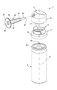
figure 1 is a perspective view of a dispenser of cryogenic substances in
accordance with the
present invention;
figure 2 is an exploded view of the dispenser of cryogenic substances of
figure 1;
figure 3 is a schematic section view, along a longitudinal plane, of the
dispenser of figure 1
and 2;
figure 3A is a detail of figure 3;
figures 4 and 5 are partial perspective views of a dispenser, in accordance
with the present
invention, placed in a safe condition;
figure 6 is a partial perspective view of a dispenser, in accordance with the
present invention,
in an intermediate condition;
figures 7 and 8 are partial perspective views of a dispenser, in accordance
with the present
invention, in a delivery condition;
figures 9A and 9B are views in detail of a container of said dispenser
according to a first
embodiment;
figures 9C and 9D are views in detail of a container of said dispenser
according to a second
embodiment;
figures 10 and 11 are perspective views of a coupling element of the dispenser
of cryogenic
substances;
figures 12 and 13 are perspective views of an activating element of the
dispenser of cryogenic
substances.
19
CA 02893073 2015-05-29
54699-40
DETAILED DESCRIPTION
Dispenser of cryogenic substances.
1 denotes in its entirety a dispenser of cryogenic substances C in particular
used for topical
treatment of tissues.
Cryogenics are often used in dermatology for treatment of various pathologies
and/or
malformations of the skin, caused by aging and other reasons, for example for
treatment of
verrucas, seborrheic keratosis, skin tags, freckles, cutaneous formations,
unaesthetic skin
conditions, etc.
The advantages in the use of cryogenics for pathologies/blemishes mentioned
above are
linked to the possibility of operating without medical assistance and,
consequently, without
the need for anaesthetics, to prevent the appearance of scars, obviate the use
of dressings and
to reduce the convalescent period post-treatment.
A cryogenic substance C is taken to mean a substance having a very low boiling
temperature,
in particular lower than -73 C; some of the more common cryogenic substances
are: dimethyl
ether, nitrogen, argon, CO2, oxygen and ammonia. The dispenser 1 of the
present invention is
configured to operate with a dimethyl ether-based mixture, though other
cryogenic substances
C could also be used.
These substances are maintained under pressure and in the liquid state
internally of an
appropriate can. As can be seen in the figures, the dispenser 1 comprises a
container (2)
configured such as to contain a predetermined quantity of cryogenic substance
(C). In the
appended figures, a preferred but not exclusive embodiment of the container 2
is illustrated,
which exhibits a substantially cylindrical shape. The container 2 is
substantially a recipient
defining internally thereof a housing chamber or compartment 2c, in fluid
communication
with the outside environment by means of at least an opening 2a. In a
preferred embodiment,
illustrated in the figures, the container 2 is provided with one and one only
opening 2a in
communication with the outside environment.
CA 02893073 2015-05-29
54699-40
The opening 2a is arranged, non-limitingly, at an upper base of the cylinder:
the opening 2a
enables exit of the cryogenic substance C along an expulsion direction E (see
figure 2).
The container 2 comprises a valve 3 active on the opening 2a and configured so
as to be
arranged in a normally closed condition in which it prevents exit of the
cryogenic substance C
of the opening 2a. The valve 3 is further configured to be arranged, following
an activating
operation thereof, in a passage condition in which the valve 3 enables outlet
of the cryogenic
substance C.
In fact, the valve 3 is a normally-closed valve which in the standard
condition prevents the
cryogenic substance C from exiting from the container 2. The activating of the
valve 3 enables
setting the chamber 2c of the container 2 in fluid communication with the
outside
environment.
As previously mentioned, the cryogenic substance C present in the container 2
is pressurized
and in the liquid state: the pressure of the cryogenic substance C, following
activation of the
valve 3, enables the substance C to be expelled from the opening 2a in the
form of gas, or,
.. alternatively, is nebulized (aerosol).
In the most common form the container 2 is in fact a spray can containing the
cryogenic
substance C in the liquid state.
In figures from 9A to 9D, and non-limitingly, two different embodiments are
illustrated of the
valve 3 mountable at the opening 2a of the container 2; in particular, in
figures 9A and 9B, a
first embodiment of the valve 3 is illustrated, while figures 9C and 9D show a
second
embodiment of the valve 3.
In the first embodiment illustrated in figures 9A and 9B, the valve 3
comprises a constraining
element 33 fixed solidly to inside the chamber 2c of the container 2, at the
opening 2a. The
element 33 exhibits an opening 34 located at the opening 2a and in fluid
communication
.. therewith. In particular, as is visible in figure 9B, the opening 34 of the
constraining element
33 is aligned with the opening 2a and is consecutively arranged with respect
thereto; in this
way the opening 34 of the constraining element 33 defines with the opening 2a
a single
21
CA 02893073 2015-05-29
54699-40
passage able to set in fluid communication the general chamber 2c of the
container 2 with the
external environment. The constraining element 33 extends internally of the
housing chamber
2c of the container between a first and a second end 35, 36 at which the
constraining element
33 comprises a first and a second axial abutment 37, 38.
The valve 3 further comprises a body 39 extending along a prevalent
development direction
and engaged internally of the opening 34 of the valve 3. The prevalent
development direction
of the body 39 is substantially parallel to the expulsion direction E (see
figure 9B) and is
mobile by sliding internally of the openings 34 and 2b (as previously
described, defining a
single passage) substantially along the expulsion direction.
In greater detail, the body 39 comprises a first portion 40 emerging from the
container 2 and a
second portion 41 located internally of the housing compartment 2c of the
container 2. The
second portion 41 comprises an abutment 42, able to abut the first axial
abutment 37 of the
constraining element 33 in the normally closed condition of the valve 3: the
first axial
abutment 37 of the constraining element 33 substantially defines an endrun
point of the body
39 so as to prevent it from exiting from the general chamber 2c of the
container 2 (see the
condition of the valve of figure 9A).
As visible in figures 9A and 9B, an elastic element 43 is engaged between the
abutment 42 of
the body 39 and the second axial abutment 38 of the constraining element 33,
which elastic
element 43 is configured so as to force contact between the abutment 42 of the
body 39 and
the first abutment 37 of the first constraining element 33.
The first portion 40 of the body 39 is configured so as to receive an opening
force directed
along the expulsion direction E and having an entering direction with respect
to the container
2; by applying on the first portion 40 of the body 39 an opening force greater
than the resistant
force provided by the elastic element 43 it is possible to slide the body 39
along a sliding
direction S that is substantially parallel to the expulsion direction E of the
cryogenic
substance.
As can be seen in figures 9A and 9B, the body 39 comprises an outlet line 44
exhibiting a first
opening 45 located at the first portion 40 and which is in fluid communication
with a second
22
CA 02893073 2015-05-29,
54699-40
opening 46 positioned on a lateral wall of the body 39. The second opening 46
is positioned in
such a way as to prevent fluid communication between the housing chamber 2c of
the
container 2 and the external environment when the valve 3 is arranged in the
normally-closed
condition: in this condition the abutment 42 of the body 39 is abutted on the
first abutment 37
of the constraining element 33 (the starting condition of the valve maintained
by the elastic
element 42 and visible in figure 9A).
In the preferred embodiment illustrated in figure 9A, the second opening 46,
in the normally
closed condition of the valve 3, is arranged externally of the housing chamber
2c of the
container 2, and in particular is aligned to the opening 2a of the container
2.
Following the translation of the body 39 along the sliding direction S (a
condition defined
following the application, on the body 39, of an opening force that is greater
than the resistant
force provided by the elastic element 43), the second opening 46 can be
arranged internally of
the housing chamber or general chamber 2c of the container 2 and place in
fluid
communication the internal volume of the container 2 with the external
environment (passage
condition of the valve 3 illustrated in figure 9B).
In this condition the second portion 41 occludes the fluid passage from the
lower zone of the
chamber towards the exit in such a way that only a predetermined quantity of
cryogenic fluid
(in particular the fluid contained in the same chamber which contains the
elastic element) can
be dispensed with the single activation.
In the second embodiment illustrated in figures 9C and 9D, the valve 3 also
comprises a
constraining element 33 solidly fixed to the inside of the container 2, at the
opening 2a. The
element 33 exhibits an opening 34 located at the opening 2a and in fluid
communication
therewith. In particular, as can be seen in figure 9C, the opening 34 of the
constraining
element 33 is aligned with the opening 2a and consecutively arranged with
respect thereto: in
this way the opening 34 of the constraining element 33 defines, with the
opening 2a, a single
passage placing the container 2 in fluid communication with the outside
environment. The
constraining element 33 extends internally of the container 2 between a first
and a second end
23
CA 02893073 2015-05-29
54699-40
35, 36 at which the constraining element 33 comprises a first and a second
axial abutment 37,
38.
The constraining element 33 illustrated for example in figure 9C (second
embodiment)
comprises a hatching device 47 defining, internally of the general chamber 2c
of the container
2, a pre-chamber 2d, in particular, interposed between the opening 2a of the
container 2 and
the general chamber 2c thereof.
In greater detail, the batching device 47 emerges distancingly from the
opening 2a of the
container 2 along a prevalent development direction between the first and a
second end 35, 36
of the constraining element 33.
= 10 At the second end 36, the batching device 47 comprises, non-
limitingly, an inlet 22 for setting
the general chamber 2c in fluid communication with the pre-chamber 2d. At the
first end 35,
the device 47 exhibits at least an outlet 23 able to place the pre-chamber 2d
in fluid
communication with the opening 2a of the container 2.
In structural terms, it can be seen that the batching device 47 exhibits, non-
limitingly, a form
of cylindrical symmetry about the expulsion direction E of the cryogenic
substance C.
As visible in figure 9B, the device 47 comprises a support portion 48 at the
second end 36 of
the device 47. The support portion 48 exhibits a housing seating 49 able to at
least partially
contain an elastic element 43, in particular a spring. The second axial
abutment 38 of the
constraining element 33 on which the elastic element 43 rests is defined at
the base of the
housing seating 49.
In fact, the elastic element 43 rests, on a side, on the second axial abutment
38 while, on the
opposite side, it is configured to abut on an end portion of the body 39 as
will be better
explained in the following.
In the preferred embodiment illustrated in figure 9C, the inlet 22 of the pre-
chamber 2dis
arranged, non-limitingly, at the base of the housing seating 49.
Alternatively, the inlet 22 can
be arranged at least at a lateral wall of the batching device 47 (a condition
not illustrated in the
figures).
24
CA 02893073 2015-05-29
54699-40
As visible in figures 9C and 9B, the batching device 47 further comprises a
closing portion
50, configured to abut the body 39 so as to define the pre-chamber 2d. In
particular, the
closing portion 50 comprises at least a tab 51 emerging from a lateral wall 52
of the device 47
nearingly to the body 39. The tab 51 terminates with an end portion 53
complementarily-
shaped to a portion of the body 39.
In the second embodiment (figures 9C and 9D), the valve 3 also comprises a
body 39
extending along a prevalent development direction and engaged internally of
the opening 34
of the valve 3. The prevalent development direction of the body 39 is
substantially aligned to
the expulsion direction 34 and 2b (as previously described defining a single
passage)
substantially along the expulsion direction E.
In greater detail, the body 39 comprises a first portion 40 emerging from the
container 2 and a
second portion 41 located internally of the pre-chamber 2d of the container 2.
Differently to
the first embodiment, the second portion 41 of the body 39 is located directly
internally of the
pre-chamber 2d which is contained internally of the general chamber 2c.
The second portion 41 comprises an abutment 42, able to abut the first axial
abutment 37 of
the constraining element 33: the first axial abutment 37 of the constraining
element 33
substantially defines an endrun point of the body 39 for preventing the body
39 from exiting
from the container 2 (condition of figure 9C).
The body 39 further comprises a further abutment 42a opposite the abutment 42
with respect
to the body 39. In fact, the further abutment 42a is arranged on a terminal
portion of the body
39 distanced from the opening 2a of the container 2. The abutment 42a is able
to contact the
elastic element 43. As visible for example from figure 9C, the elastic element
43 is interposed
between the further axial abutment 42a of the body 39 and the second axial
abutment 38 of the
constraining element 33. The elastic element 43 is configured so as to force
contact between
the abutment 42 of the body 39 and the first abutment 37 of the first
constraining element 33
and maintain it in the normally-closed condition.
As with the first embodiment, the first portion 40 of the body 39 is
configured so as to receive
an opening force directed along the expulsion direction E and having an
entering direction
CA 02893073 2015-05-29
54699-40
with respect to the container 2; by applying on the first portion 40 of the
body 39 an opening
force greater than the resistance force offered by the elastic element 43 it
is possible to slide
the body 39 along a sliding direction S substantially parallel to the
expulsion direction E of
the cryogenic substance C (figure 9D).
In the second embodiment illustrated in figures 9C and 9D, the body 39 further
comprises an
abutment 54 able to abut on the end portion 53 of the tab 51 following the
translation of the
body 39 internally of the container 2.
In fact, in the endrun condition of the body 39, i.e. in the condition in
which the first abutment
37 of the constraining element 33 is in contact with the abutment 42 of the
body 39, the
abutment 54 is distanced from the end portion 53 (figure 9C). While, following
the translation
of the body 39 (translation of the body along the sliding direction S)
internally of the
container 2, the endrun 54 abuts on the end portion 53 (figure 9D).
As with the first embodiment, the body 39 of figure 9C-9D comprises an outlet
line 44
exhibiting a first opening 45 located at the first portion 40 and which is in
fluid
communication with a second opening 46 located on a lateral wall of the body
39. The second
opening 46 is positioned such as to prevent fluid communication between the
container 2 and
the external environment when the valve 3 is arranged in the normally-closed
configuration:
in this condition the abutment 42 of the body 39 is abutted to the first
abutment 37 of the
constraining element 33 (starting condition of the valve illustrated in figure
9C).
In the preferred embodiment illustrated in figure 9C, the second opening 46,
in the normally
closed condition of the valve 3, is arranged externally of the housing chamber
2c of the
container 2, in particular it is aligned to the opening 2a of the container 2.
Following the translation of the body 39 along the sliding direction S (a
condition defined
following the application on the body 39 of an opening force greater than the
resistant force
offered by the elastic element 43), the second opening 46 can be arranged
internally of the
container 2, in particular internally of the pre-chamber 2d, and can set the
pre-chamber 2d in
fluid communication with the external environment (figure 9D).
26
CA 02893073 2015-05-29
54699-40
In detail, in the second embodiment, the movement of the body 39 internally of
the container
2 enables the abutment 54 of the body 39 to abut on the end portion 53 of the
tab 51: in this
way the body 39, in particular the abutment 54, obstructs the inlet 22 of the
pre-chamber 2d in
such a way as to prevent passage of fluid between the pre-chamber 2d and the
general
chamber 2c.
In fact, also in the second embodiment illustrated in figures 9C-9D, only the
predetermined
quantity of cryogenic substance C arranged internally of the pre-chamber 2d
can exit from the
container 2 during the passage condition of the valve 3.
In the closed condition of the valve 3, the fluid communication between the
general chamber
2c and the pre-chamber 2d enables injecting into the pre-chamber 2d further
cryogenic
substances C to be dispensed during a subsequent passage condition of the
valve.
It is useful to note that in both the embodiments, independently of how long
the valve 3 of the
dispenser 1 is maintained in the passage condition, only the predetermined
quantity of
cryogenic substance C contained in the pre-chamber 2d can be dispensed through
the opening
2a of the container 2.
Continuing with the description of the container 2, it is possible to observe
that the container
further comprises an engaging portion 2b located at the opening 2a. The
engaging portion 2b
can define at least an undercut with respect to the expulsion direction E of
the cryogenic
substance C. In the preferred embodiment, for example visible in figure 3, the
engaging
portion 2b of the container 2 comprises a fold 55 exhibiting, non-limitingly,
a circular
development defining a closed profile.
The dispenser 1 further comprises a coupling element 4 constrained stably to
the container 2
substantially at the opening 2a. In particular the coupling element 4
comprises a first engaging
portion 10 constrained to the engaging portion 2b of the container 2.
In greater detail, the first engaging portion 10 of the coupling element 4 is
able to abut in
undercut on the engaging portion 2b of the container 2: in this way the
container axially
27
CA 02893073 2015-05-29
=
54699-40
constrains the coupling element 4 so as to prevent it from translating along
the expulsion
direction E.
As is visible for example in figure 3, the first engaging portion 10 of the
coupling element 4
comprises, in a non-limiting way, a seal element 56 at least partly
complementarily-shaped to
the engaging portion 2b of the container 2. This seal element 56 exhibits at
least a projection
57 able to abut the undercut of the engaging portion 2b. In the preferred
embodiment,
illustrated for example in figures 10 and 11, the seal element 56 is entirely
complementarily
shaped to the engaging portion 2b of the container, in particular defining a
lateral wall having,
in a transversal section, a circular profile; the projection 57 emerges from
the lateral wall
nearingly to the undercut of the element of the container 2.
As visible for example from the section view of figure 3, the first engaging
portion 10 further
comprises an abutting element 58 connected to the seal element 56, in
particular joined in a
single piece therewith, able to rest on the engaging portion 2b of the
container 2. In particular,
the seal element 56 and the abutting element 58 define a substantially L-
shaped profile
entirely in contact with the engaging portion 2b: the engaging portion 2b is
substantially
interposed between the projection 57 and the abutting element 58 of the
coupling element 4.
The coupling element 4 further comprises a second engaging portion 11 emerge
from the first
engaging portion 10 distancingly with respect thereto, in particular, parallel
to the expulsion
direction E of the cryogenic substance C.
In greater detail, the second engaging portion 11 of the coupling element 4
exhibits a lateral
wall 18 extending substantially parallel to the expulsion direction E. The
lateral wall 18
exhibits, in a non-limiting way, a hollow cylindrical shape developing about
an axis A parallel
to the expulsion direction E and having a smaller radial dimension with
respect to the radial
dimension of the seal element 56.
The lateral wall 18 is non-limitingly joined in a single piece with the
abutting element 58; in a
longitudinal section, the abutting element 58 and the lateral wall 18 define a
substantially L-
shaped profile (see the section view of figure 3 and the detailed view of
figure 3A).
28
CA 02893073 2015-05-29
54699-40
The second portion 11 of the coupling element 4 is configured so as to engage
and cooperate
with an activating element 5 which will be more fully described in the
following.
In particular, the second engaging portion 11 comprises a further projection
59 arranged
internally of the lateral wall 18 and configured so as to engage the
activating element 5. As
visible in the detail of figures 10 and 11, the projection 59 extends over all
the lateral wall 18
such as to form a circular profile along a transversal plane, in particular
perpendicular, to the
axis A of the coupling element 4.
As visible from the figures, the second engaging portion 11 of the coupling
element 4 further
comprises at least a blocking portion 7. The blocking portion 7 is, non-
limitingly, arranged on
the lateral wall 18 and emerges with respect to a lateral external surface
thereof, for example
in the form of a tooth provided with an inclined wall connected to the lateral
wall 18 which
terminates with a perpendicular surface to the lateral wall.
In other terms the blocking portion 7 exhibits at least a projection 15
defining a radial
intersection portion 16 and a support portion 17 (see figures 10 and 11).
The radial intersection portion 16 defines a radial undercut emerging from the
external lateral
surface of the wall 18. The support portion 17 is instead able to
substantially define an axial
blocking portion along the expulsion direction E of the cryogenic substance C
(as will be
more fully described in the following).
The figures represent a preferred embodiment of the radial intersection
portion 16 which
develops, non-limitingly, over all the height-extension of the wall 18 along
the axis A
(parallel to the expulsion direction E). The radial intersection portion 16
exhibits, according to
a transversal section, a substantially triangular profile (with a tooth).
In the figures a preferred embodiment is illustrated in which the coupling
element 4 exhibits
two blocking portions 7, angularly offset (more precisely, opposite) with
respect to one
.. another in relation to the axis A of the coupling element 4.
In an alternative realisation, not illustrated in the accompanying figures,
there can be a
number of blocking portions that is greater than 2 or even one only blocking
portion.
29
CA 02893073 2015-05-29
54699-40
As visible for example from the detail of figures 10 and 11, the second
engaging portion 11 of
the coupling element 4 further comprises at least a passage seating 8. The
seating is non-
limitingly arranged at the lateral wall 18 and extends substantially over the
whole axial
development thereof, parallel to the axis A of the coupling element 4.
.. The passage seating 8 defines, non-limitingly, a through-seating crossing
the lateral wall 18
(or, in other terms, an interruption of the lateral wall 18) which defines a
straight line parallel
to the axis A (parallel to the expulsion direction E of the cryogenic
substance C).
The passage seating 8 is angularly offset with respect to the blocking portion
7 in relation to
the expulsion direction E, in particular with respect to the axis A of the
coupling element 4. In
the preferred embodiment, there is non-limitingly a number of passage seatings
8 equal to the
number of blocking portions 7. In particular, a configuration of the dispenser
1 is illustrated
that exhibits, non-limitingly, two blocking portions 7 and two respective
passage seatings 8.
As visible for example in figures 10 and 11, the passage seating 8 is
optionally offset
angularly by 90 with respect to the blocking portion 7. As can be seen in
figures 10 and 11,
the lateral wall 18 can further comprise a radial endrun portion 60
circumferentially distanced
with respect to each blocking portion 7 and to each passage seating 8.
Further, the lateral wall
18 can comprise an axial projection 61 (see figure 10) emerging from an upper
surface of the
wall 18. The axial projection 61 is preferably arranged at the passage seating
8 so that the
seating is interposed between the radial endrun 60 and the axial projection 61
(see figure 10).
Alternatively the axial projection 61 could be replaced by a small relief
(such a tooth
projecting less than the tooth 15 and with opposite inclined surface, not
shown in the figures)
positioned at the lateral wall 18 and with the aim of providing a tactile
and/or acoustic
indication of the reaching of position of an activating element. The structure
and function of
the endrun 60 and the projection 61 will be more fully described in the
following.
As previously mentioned, the dispenser 1 further comprises an activating
element 5 engaged
to the coupling element 4. In greater detail, the activating element 5 is
engaged to the second
engaging portion 11 of the coupling element 4 so that the coupling element 4
is interposed
between the container 2 and the activating element 5.
CA 02893073 2015-05-29
=
54699-40
In structural terms, the activating element 5 comprises a body 5c defining
internally thereof a
housing compartment 5a: in the engaging condition between the activating
element 5 and the
coupling element 4, the second portion 11 thereof is at least partly arranged
internally of the
housing compartment 5a.
As visible in figure 12, internally of the housing compartment 5a of the
activating element 5
there is an engaging portion 20 able to abut to the second engaging portion 11
of the coupling
element 4. The engaging portion 20 emerges from the internal wall of the
housing
compartment 5a parallel to the expulsion direction E of the cryogenic
substance C
(consequently parallel to the axis A of the coupling element 4) in order to
insert in the lateral
wall 18 of the coupling element 4). The engaging portion 20 exhibits, non-
limitingly, a hollow
cylindrical shape complementarily-shaped to the lateral wall 18 of the
coupling element 4. In
order to enable the constraint between the coupling element 4 and the
activating element 5,
= the activating element exhibits an abutment 21 able to abut the further
projection 59 arranged
internally of the lateral wall 18: in this condition the further projection 59
of the lateral wall
.. 18 defines an axial undercut for the abutment 21 which can stably constrain
the activating
element 5 to the blocking element (substantially preventing translation of the
activating
element distancingly with respect to the container 2).
The engaging portion 20 of the activating element 5 further enables centring
thereof on the
coupling element as well as guiding thereof during the relative movement (see
also the section
.. of figure 3).
A dispensing conduit 6 is present internally of the engaging portion 20 of the
activating
element 5, which dispensing conduit 6, in the engaged condition between the
coupling
element 4 and the activating element 5, is in fluid communication with the
opening 2a of the
container 2; this conduit 6 is configured so as to guide the emission of the
cryogenic substance
C towards the external environment.
In greater detail, the dispensing conduit 6 exhibits an abutting portion 62
(visible in figure 12)
in contact with the first portion 40 of the body 39 emerging from the
container 2; the outlet
line 44 of the body 39 is in fluid communication with the dispensing conduit
6. During the
31
CA 02893073 2015-05-29
54699-40
passage condition of the valve 3, the cryogenic substance C is able to exit
from the line 44,
enter the dispensing conduit 6 and then exit from the activating element 5.
As is visible from the section view of figure 3, and the detail of figure 3A,
the activating
element 5 further comprises an active portion 9 which cooperates with the
blocking portion 7
.. and the passage seating 8 of the coupling element 4.
In particular, the activating element 5 is configured so as to define, in
cooperation with the
coupling element 4, at least a dispensing condition in which the active
portion 9 of the
activating element 5 is at and cooperates with the passage seating 8; in
particular in the
dispensing condition the active portion is translatable in the seating 8 along
a sliding direction
S nearingly to the container 2.
Following the activation along the expulsion direction towards the container
2, the activating
element 5 is configured so as to arrange the valve 3 in the passage condition
and consequently
enable the exiting of at least a part of the cryogenic substance C from the
opening 2a.
The activating element 5 is further configured to define, in cooperation with
the coupling
element 4, at least a safety condition.
The safety condition is attained by relative rotation (by about 900) of the
activating element 5
with respect to the coupling element 4.
In the safety condition, the active portion 9 of the activating element 5 is
abutted to the radial
endrun portion 60 of the coupling element 4 located at the projection 15 of
the coupling
element 4.
In this condition, a lower appendage 9a of the active portion is intercepted
by the
projection 15.
In detail, the lower appendage 9a abuts against the radial intersection
portion 16 and prevents
a rotation of the active portion 9 (and therefore the activating element 5)
towards the passage
seating 8, i.e. towards the dispensing condition.
32
CA 02893073 2015-05-29
54699-40
In other terms the cooperation between the projection 15 and the active
portion 9 (or more
accurately the inferior appendage 9a thereof) prevents a relative rotation of
the two
components coupled in an anticlockwise direction in the figures.
Obviously the rotation in the opposite direction (clockwise) is prevented by
the cooperation of
the active portion abutting against the abutting surface 60 defined by the
radial endrun.
In this way the activating element 5, in the safety condition, is stably
blocked to the coupling
element 4 and relative rotations are not allowed.
Note that in this safety condition, the dispensing of the cryogenic substance
is not enabled as
the active portion 9 rests on the support portion 17 of the coupling element 4
and does not
enable an axial nearing of the two bodies 4 and 5.
= The activating element 5 is further configured so as to define, in
cooperation with the
coupling element 4, at least an intermediate condition in which the activating
element 5 is
mobile in relation to the coupling element in rotation about the axis A
substantially parallel to
the expulsion direction E: the activating element 5, in the intermediate
condition, can be
displaced from the dispensing condition to the safety condition and vice versa
(see the
schematic representation in figure 6).
This intermediate condition occurs when the projection 15 and the lower
appendage 9a of the
active portion are disengaged and therefore anti-clockwise rotation of
components 4 and 5 is
enabled.
However, as long as the active portion 9 is not exactly at the seating 8, each
relative axial
translation between the bodies 4 and 5 is prevented and there cannot be any
dispensing of
cryogenic substance.
The active portion 9 of the activating element 5 comprises, non-limitingly, at
least the lower
appendage 9a, in detail constrained to and emerging from an internal lateral
wall 5b of the
housing compartment 5a and nearingly to the coupling element 4. As previously
described,
the lateral wall 18 of the coupling element (bearing the blocking portion and
the passage
seating 8) is arranged internally of the housing compartment 5a of the
activating element 5;
33
CA 02893073.2015-05-29
54699-40
the lower appendage 9a of the active portion 9 emerges from the lateral
internal wall 5b of the
housing compartment 5a nearingly to the lateral wall 18 so that lateral wall
18 is interposed
between the internal lateral wall 5b and the engaging portion 20 of the
activating element (see
the section view of figure 3 and the detail of figure 3A). In geometrical
terms, the lower
appendage 9a defines an interruption of the ribbing 19 emerging substantially
perpendicularly
to the internal lateral wall 5b of the housing compartment 5a between a first
and a second
lateral surface. The distance of the surfaces defines the thickness of the
ribbing 19 which is
smaller than the width of the passage seating 8.
As previously mentioned, the active portion 9 cooperates with both the
blocking portion 7 and
with the passage seating 8. In particular, as will be better described in the
following, the
ribbing 19 (active portion 9) of the activating element 5 is configured so as
to slide internally
of the passage seating 8 is configured so slide internally of the passage
seating 8: for this
reason the dimensions of the ribbing 19 are smaller than the corresponding
dimensions of the
seating 8 in the width direction.
The lower appendage 9a of the activating element 5 substantially defines a
radial intersection
surface 13 and an axial intersection surface 14 which, in the safety condition
(see for example
figures 4 and 5), are abutted respectively to the radial intersection portion
16 and to the
support portion 17 of the coupling element 4. In the safety condition, the
radial intersection
portion 16 and the support portion 17 of the coupling element 4 are configured
so as to
prevent respectively the rotation and the axial translation of the activating
element 5. In fact,
the activating element 5, during the safety condition, is not mobile in
relation to the coupling
element 4.
In greater detail, the radial intersection portion 16 of the coupling element
4 defines a radial
undercut with respect to the radial intersection surface 13 of the activating
element 5: the
radial intersection surface 13 of the activating element 5, during the safety
condition, is
abutted to the radial intersection portion 16 of the coupling element 4 and
blocked in
movement with respect thereto.
34
CA 02893073 2015-05-29
54699-40
Regarding the axial intersection surface 14 of the activating element 5, at
least in the safety
condition the activating element 5 is abutted to the support portion 17 of the
coupling element
4 so as to prevent the activating element 5, at least in the safety condition,
from translating
along the expulsion direction E nearingly to the container 2.
The impossibility of translation by the activating element 5 nearingly to the
container 2
prevents the dispensing conduit 6 from pushing the body 39 internally of the
container 2 so as
to arrange the valve 3 in the passage condition. In fact, during the safety
condition the valve 3
is not activatable and dispensing of the cryogenic substance C is not enabled.
As previously described, the activating element 5 and the coupling element 4
are configured
so as to further define a dispensing condition in which the active portion 9
is slidingly mobile
nearingly to the container 2. In this condition, the active portion 9 is at,
and is inserted in the
passage seating 8 (angularly offset with respect to the blocking portion 7)
and can slide
internally of the seating 8.
As previously described, the dispensing conduit 6 is resting on the portion 40
of the body 39:
the nearing translation to the container 2 enables the abutting portion 62 of
the conduit 6 to
push the body 39 internally of the container 2 and arrange the valve 3 in the
passage
condition. In fact, in the dispensing condition, the axial sliding of the
activating element 5
along the direction of expulsion E enables emission of the cryogenic substance
C.
In the intermediate condition, the activating clement 5 is mobile in rotation
relatively to the
.. coupling element 4 so as to enable passage from the safety condition to the
dispensing
condition and vice versa (see figure 6). In the intermediate condition, the
axial intersection
surface 14 of the activating element 5 is abutted on the support portion 17 of
the coupling
element 4 which prevents the activating element 5 from moving in a nearing
direction to the
container 2. In fact, in the intermediate condition, the activating element 5
can only rotate
with respect to the coupling element 4 without being able to push the body 39
internally of the
container 2 and consequently cause the activation of the valve 3.
To enable passage from the safety condition to the intermediate condition, the
activating
element 5 is configured so as to deform elastically, following the application
of an external
CA 02893073,2015-05-29
54699-40
solicitation F (see figure 5) so as to allow decoupling between the active
portion 9 of the
activating element 5 (in particular the lower appendage (9a) and the blocking
portion 7 of the
coupling element 4.
In particular, the activating element 5, following the application of the
external solicitation F,
can be arranged in the intermediate condition and consequently pass from the
safety condition
to the dispensing condition.
As visible for example from figures 4 to 8, the body Sc of the activating
element 5 exhibits at
least a thrust portion 5d located at a lateral external wall 5e of the body
Sc. The thrust portion
5d is configured so as to receive the external solicitation F directed
transversally to the
expulsion direction E (transversal to the sliding direction S) and having an
entering direction
with respect to the housing compartment 5a; the thrust portion 5d, following
the application of
the external solicitation F, is configured so as to elastically deform at
least a portion of the
body Sc so as to allow distancing of the lower appendage 9a of the activating
element 5 from
the blocking portion 7 of the coupling portion 4 so as to allow decoupling
thereof.
In fact, the distancing of the lower appendage 9a with respect to the lateral
wall 18 enables
radially freeing the intersecting portion 13 of the activating element 5 with
respect to the
intersecting portion 16 of the coupling element 4: in this way the last
portion no longer
defines a radial undercut for blocking the rotation of the activating element
5 which can be
arranged in the intermediate condition and thereafter in the dispensing
condition.
In the preferred condition illustrated in the figures of the drawings, the
thrust portion 5a is
angularly offset in relation to the active portion 9 with respect to the axis
A; in particular it is
offset by 90 with respect to the active portion 9.
The body 5c advantageously exhibits two thrust portions 5d positioned
symmetrically to one
another with respect to the axis A (a favourable condition for gripping and
deforming the
body Sc).
In this way the operator, acting with two fingers of the same hand, deforms
the activating
element 5 to bring it from a circular configuration to a helical configuration
in which the
36
CA 02893073.2015-05-29
54699-40
lower appendage 9a (or the lower appendages 9a if there are two opposite) is
at the larger axis
of the ellipse, distancing and disengaging from the projection 15 of the
coupling element and
in that configuration being able to be rotated and disengaged definitively
from the projection.
As previously described, the coupling element 4 comprises a radial endrun
portion 60 which is
positioned at the passage seating 8 and at the blocking portion 7. The portion
60 is configured
so as to contact the active portion 9 of the activating element 5 when the
activating element
passes from the intermediate condition to the safety condition or dispensing
condition. In fact,
the portion 60 defines an endrun position which enables alignment of the
active portion 9 with
the passage seating 8 and with the blocking portion 7. In greater detail, the
radial endrun
portion 60 prevents the activating element 5 from rotating into an erroneous
position,
dealigned with the seating 8 and/or with the portion 7.
As previously described, the coupling element 4 further comprises an axial
projection 61 (see
figure 10) located on an upper support surface of the wall 18. This projection
61 is configured
so as to contact the active portion 9 when the activating element 5 is in the
intermediate
condition and shortly prior to defining the dispensing element. The projection
61 represents,
in fact, a step which enables the user to note the passage between the
intermediate condition
and the dispensing condition.
As already mentioned, a tooth might be additionally or alternatively present,
emerging from
the lateral wall 18 located at the seating 8 and with the aim of informing the
user that the
desired position has been reached.
As is visible from the figures, the dispenser 1 further comprises an
applicator 25 engaged to
the activating element 5 and configured so as to receive the cryogenic
substance C in arrival
from the dispensing conduit 6 and guide the cryogenic substance C towards the
zone to be
treated.
In structural terms, the applicator 25 exhibits a body 26 extending along a
prevalent
development direction between a first and a second end 27, 28. The applicator
25 is engaged,
at the first end 27, to the activating element 5 and emerges from the lateral
external wall 5e
37
CA 02893073.2015-05-29
54699-40
thereof in an exiting direction with respect to the housing compartment 5a of
the activating
element 5.
The applicator 25 exhibits a through-opening 29 along all the body 26 (from
the first end 27 to
the second end 28) which is in fluid communication with the dispensing conduit
6 of the
activating element 5.
In particular, the opening 29 defines at the first and second end 27, 28,
respectively a first and
a second passage opening 31, 32.
The applicator 25 functions substantially as a diffuser: the first passage
opening 31 defines a
smaller passage area defined by the second passage opening 32. In particular,
the opening 29
exhibits a cylindrical shape about a substantially parallel axis to the
prevalent development
direction of the applicator 25; the opening 29 exhibits a truncoconical shape
having a growing
passage section from the first end 27 in the direction of the second end 28.
The shape of the
applicator 25 is optimal for the flow concentration directly on the part to be
treated.
It is useful to specify that for a correct application of the cryogenic
substance C it is advisable
to maintain a determined distance from the application zone. The elongate
shape of the
applicator 25 enables correctly distancing the outlet zone of the dispensing
conduit 6 of the
cryogenic substance C from the zone on which it is to be applied.
The applicator 25 can advantageously be realised, at least at the second end
28, with a
transparent material enabling viewing of the zone to be treated also when the
applicator 25 is
in contact therewith. The transparency of at least part of the applicator 25
facilitates the
viewing of the zone to be treated, in order to be able to perform the
treatment with precision.
A preferred embodiment of the applicator 25 is reported in the figures, which
comprises a
support portion 63 that enables a correct positioning of the applicator 25 on
the application
zone during the dispensing step. In fact the support portion 63 comprises, non-
limitingly, a
disc emerging transversally with respect to the prevalent development
direction of the body
26. In a preferred embodiment, illustrated in the figures, the support portion
63 exhibits a
widened circular shape which substantially develops a platform for supporting
the applicator
38
CA 02893073.2015-05-29
= 54699-40
25 on the part to be treated, so that the dispenser 1 is maintained in a
perpendicular position
during the treatment, preventing swinging movements that are disadvantageous
for the
effectiveness of the treatment.
The figures relate to a preferred embodiment of the applicator 25 which
further comprises at
least a slit 30 arranged on the external lateral wall of the body 26 and which
places the
opening 29 in fluid communication 29 with the outside environment. The slit 30
is particularly
useful in a case where the applicator 25 is placed in contact with the
application zone: in this
case the slit 30 functions as a discharge opening for optimizing the freezing
effect of the
cryogenic substance which enables maintaining the second end 28 of the body 26
supported
during dispensing of the substance C.
In greater detail, the slit 30, located advantageously in the terminal part of
the applicator 25
(substantially at the second end) is specially structured and predisposed to
facilitate contact of
the cryogenic substance C with the oxygen with the aim of more rapidly
obtaining the
freezing effect. In the figures, a non-limiting preferred embodiment of the
applicator 25 is
shown, exhibiting four slits 30 exhibiting an extension parallel to the
prevalent development
direction of the body 26 of the applicator 25; the slits 30 extend starting
from the second end
28 nearingly to the first end of the applicator 25.
The slits 30 are advantageously distributed uniformly about the body 26 of the
applicator 25
so as to allow uniform contact of the cryogenic substance C with the oxygen.
The applicator 25 is advantageously configured so as to removably engage the
activating
element 5: in this way different types of applicators 25 can be comprised,
mountable on the
activating element 5, having different geometrical and/or physical
characteristics (for example
the length, dimension of the opening and the material with which the
applicator is realised).
The removability of the applicator 25 makes the dispenser extremely flexible
and adaptable to
different zones to be treated, which can exhibit for example different
dimensions. It is
possible to include a series of applicators 25, adaptable to the dispenser 1,
having different
outlet diameters of the cryogenic substance, so as to precisely carry out the
treatment of the
various dimensions of the marks and/or lesions to be treated.
39
CA 02893073 2015-05-29
54699-40
As regards the coupling, the applicator might be forced into the seating of
the activating
element or snap-removable engagements might be used, or the like.
Method for dispensing cryogenic substances.
An object of the present invention is a method for dispensing cryogenic
substances, in
particular used for treatment/destruction of skin blemishes and/or bad or
diseased skin tissue.
The dispensing method of the present invention includes at least a dispensing
step in which
the active portion 9 is slidingly mobile in the passage seating 8 along
sliding direction S,
substantially parallel to the expulsion direction E, nearingly to the
container 2. The nearing
along the expulsion direction E of the activating element relatively to the
container 2 arranges
the valve 3 of the container 2 in the passage condition so as to enable exit
of at least a part of
the cryogenic substance C from the opening 2a (this condition is illustrated
in figure 8).
In greater detail the dispensing step includes a sub-step of sliding in the
ribbing 19 internally
of the passage seating 8. The nearing of the activating element 5 enables the
abutting portion
62 of the dispensing conduit 6 to push the body 39 internally of the container
2. The
.. dispensing step thus includes the sliding, according to an entering
direction with respect to the
container 2, both of the activating element 5 and the body 39: this causes
activation of the
valve 3 with a consequent arrangement thereof in the passage condition in
which the
cryogenic substance C can exit from the container 2.
As previously described, the body 39 of the valve 3 is pushed by an elastic
element 43 able to
maintain the valve 3 in the normally closed condition in which exit of the
cryogenic substance
C from the container 2 is not enabled. The dispensing step comprises a sub-
step of pushing the
activating element 5 nearingly to the container 2 directed on the opposite
side to the resistant
force provide by the elastic element 43. By applying a push P on the
activating element 5
greater than the resistant force of the elastic element 43, the activating
element 5 can be slid
(consequently the body 39) along the sliding direction S and the valve 3 of
the container 2
predisposed in the passage condition (see figure 8).
CA 02893073.2015-05-29
54699-40
The method further comprises an intermediate movement step in which the
activating element
is displaced relatively to the coupling element 4 by rotation about an axis A
substantially
parallel to the expulsion direction E (this step is schematized in figure 6).
During the step of intermediate movement the axial portion of intersection 14
of the activating
5 element is abutted to an upper surface of the wall 18: this prevents the
activating element 5
from sliding nearingly to the container and consequently activating the valve
3.
The intermediate movement step includes only relative rotation of the
activating element 5
with respect to the coupling element 4: during this intermediated step the
activating element 5
stays the same distance from the container 2 at all times.
The method further comprises at least a safety blocking step in which the
active portion 9 of
the activating element 5 is abutted to the blocking portion 7 of the coupling
element 4 and is
stably blocked to the coupling element 4. In fact, during the safety blocking
step the activating
element 5 is not mobile with respect to the coupling element 4, neither
axially nor radially.
In greater detail, during the safety blocking step, the radial intersection
surface 13 and the
axial intersection surface 14 of the activating element 5 are abutted
respectively to the radial
intersection portion 16 and to the support portion 17 of the coupling element
4: the radial
intersection portion 16 and the support portion 17 of the coupling element 4
respectively
block the rotation and translation of the activating element 5.
The method comprises an unblocking step which comprises a step of elastically
deforming at
least a part of the activating element 5 following application of an external
stress F. The
elastic deformation step is configured such as to enable decoupling between
the blocking
portion 7 of the coupling element 4 and the active portion 9 of the activating
element 5 when
they are in the safety step such as to enable passage between the safety step
and the
intermediate step.
The elastic deformation step comprises application of the external
solicitation F, directed
transversally to the expulsion direction E and having an entering direction
with respect to the
activating element 5, on the thrust portion 5d (this step is schematically
illustrated in figure 5);
41
CA 02893073 2015-05-29
=
54699-40
at least a part of the body 5c of the activating element 5, following
application of the external
solicitation F, elastically deforms so as to enable distancing and decoupling
of the active
portion 9 of the activating element 5 with respect to the blocking portion 7
of the coupling
element 4.
As previously described, in the preferred embodiment that thrust portion 5d is
angularly offset
by 90% with respect to the active portion 9 relative to the expulsion
direction E; the elastic
deformation step includes application of the external solicitation F in an
angularly offset point
with respect to the position of the active portion 9 of the activating element
5.
During the elastic deformation step, the ribbing distances from the lateral
wall 18 of the
.. coupling element 4: following the distancing, in particular a radial
distancing, the activating
element 5 can rotate in relation thereto about the expulsion axis E.
The method further comprises a step of directing the cryogenic substance C in
outlet from the
dispensing conduit 6 and a preceding sub-step of predisposing the applicator
25 in fluid
communication with the dispensing conduit 6 of the activating element 5.
.. The freezing of the zone to be treated is done by resting the support
portion 63 directly on the
skin, which facilitates the application of the cryogenic substance C
perpendicularly to the
zone to be treated, preventing swinging movements which facilitate treatment
in oblique
positions which would produce an asymmetric freezing, disadvantageous for the
effectiveness
of the treatment. During the directing step, the applicator 25 enables
distancing the dispensing
conduit 6 from an application zone of the cryogenic substance C.
The method preferably includes application of the cryogenic substance C
directly by resting
the support portion 63 of the applicator 25 on the part to be treated, taking
attention to
centring the perimeter to be treated, with the pre-batched flow. The method
advantageously
includes consecutive dispensing established according to the lesion and the
dimensions of the
area to be treated; this enables expansion of the freezing-line from the
centre towards the
periphery, preventing swinging movements, up to producing a visible freezing-
line on the skin
which has to be at least lmm greater than the perimeter of the blemish and/or
lesion to be
eliminated.
42
CA 02893073,2015-05-29
54699-40
ADVANTAGES OF THE INVENTION
The present invention enables important advantages to be attained with respect
to the
dispensers of cryogenic substances and dispensing methods of the substances
known today.
As previously mentioned, cryogenic treatment requires special precautions as
the state of the
substance with which the treatment is performed can cause burns or, if
dispensed on
unsuitable zones for treatment, can cause grave lesions.
The above-described dispenser 1 comprises a safety system defined by the
cooperation of the
blocking portion 7 of the coupling element 4 and the active portion of the
activating element
5. The safety system prevents the activating element 5 from causing accidental
dispensing of
= 10 cryogenic substance C.
The unblocking of the activating element 5 requires a step of elastic
deformation of at least a
part of the body 5c of the activating element and a subsequent rotation
thereof so as to bring it
into the dispensing condition. These operations certainly cannot occur
accidentally, which
guarantees the dispenser 1 will prevent undesired dispensing.
The dispenser 1 comprises a valve 3 exhibiting a pre-chamber 2d which enables
dispensing
predetermined quantities of cryogenic substance smaller than the total
quantity present in the
container 2. This characteristic enables supplying suitable pre-batched
quantities which can
prevent excessive dispensing and/or wasting of cryogenic substance.
Further, the dispenser 1 comprises an applicator 25 that can enable correcting
directing of the
cryogenic substance C on the application zone and further a correct distancing
thereof from
the outlet of the dispensing conduit 6. In particular, the applicator 25 is
made with the right
height which enables performing the treatment from the ideal distance for
facilitating
expansion of the freezing front-line from the centre towards the periphery so
as to optimize
the effectiveness of the treatment.
The terminal part of the applicator 63 has a circular disc-shape, specially
structured to be used
as a "platform" for suitable resting the applicator on the zone to be treated,
so that during the
treatment the device is maintained in a perpendicular position, prevent
swinging movements,
43
CA 02893073.2015-05-29
54699-40
which would produce an asymmetric freezing that is disadvantageous for the
effectiveness of
the treatment.
44
CA 02893073.2015-05-29
54699-40
LEGEND
1 dispenser of cryogenic substances
2 container
2a container opening
2b engaging portion of the container 2
2c general chamber
2d pre-chamber
3 valve
= 4 coupling element
5 activating element
5a housing compartment
5b internal lateral wall of through housing 5a
5c body
5d thrust portion
5e external lateral wall
6 dispensing conduit
7 blocking portion
8 passage seating
9 active portion
9a lower appendage
10 first engaging portion of the coupling element 4
11 second engaging portion of the coupling element 4
12 projection of the second engaging portion 11
13 radial intersection surface of the activating element 5
CA 02893073.2015-05-29
54699-40
14 axial intersection surface of the activating element 5
15 projection of the coupling element 4
16 radial intersection portion of the coupling element
17 support portion of the coupling element
18 lateral part of the coupling element 4
19 ribbing of the activating element 5
20 engaging portion of the activating element 5
21 abutment
22 inlet of pre-chamber 2d
23 outlet of pre-chamber 2d
24 valve
25 applicator
26 body of applicator 25
27 first end of the applicator 25
.. 28 second end of the applicator 25
29 opening
30 slit
31 first opening
32 second opening
33 constraining element
34 opening of the constraining element
35 first end
36 second end
37 first axial abutment
46
CA 02893073.2015-05-29
=
54699-40
38 second axial abutment
39 elongate body of the valve 3
40 first portion
41 second portion
42 abutment
43 further abutment
42a elastic element
44 outlet line of the valve 3
45 first opening
46 second opening
47 batching device
48 support portion
49 housing seating
50 closing portion
51 tab
52 lateral wall of the batching device 47
53 end portion of the batching device 47
54 abutment
55 fold
56 seal element
57 projection
58 abutting element
59 further projection
60 radial endrun portion
47
CA 02893073 2015-05-29
54699-40
61 axial portion
62 abutting portion
63 support portion
A axis
C cryogenic substance
E expulsion direction
F external solicitation
S sliding direction
48