Note: Descriptions are shown in the official language in which they were submitted.
CA 02893366 2015-06-01
WO 2014/099496
PCT/US2013/074126
KNOCKOUT FOR USE WHILE NECKING A METAL CONTAINER, DIE SYSTEM FOR
NECKING A METAL CONTAINER AND METHOD OF NECKING A METAL CONTAINER
BACKGROUND
[0001] It is well-known to neck the top side wall of drawn and ironed
metal
containers with a necking die to narrow the opening of the metal containers to
accept a lid
or to form the metal container into a bottle. Necking the top side wall of
drawn and ironed
metal containers requires a knockout, which works in harmony with the necking
die.
SUMMARY
[0002] One embodiment of a die system comprises a metal container, a
necking die
and a knockout. The metal container has an opening and a container side wall.
The
container side wall has a first inner diameter and a second inner diameter,
wherein the first
inner diameter of the container side wall is at least 0.001 inch greater than
the second inner
diameter of the container side wall. The necking die has a working surface
comprising a
land. The knockout has a support surface. The support surface has a first
knockout outer
diameter capable of supporting the first inner diameter of the container side
wall when the
knockout is inserted into the opening of the metal container and when the
metal container
is being necked with the necking die; and a second knockout outer diameter
capable of
supporting the second inner diameter of the container side wall when the
knockout is
inserted into the opening of the metal container and when the metal container
is being
necked with the necking die. The first knockout outer diameter is larger than
the second
knockout outer diameter.
[0003] The metal container may be any type of metal container including
beverage
cans and cups, aerosol cans and food containers. The metal container can be
made by any
1
CA 02893366 2016-11-18
process known in the art including but not limited to: drawing and ironing;
impact extrusion;
spin forming; draw and redraw; and deep drawing.
[0004] A container side wall is the body of the container.
[0005] A necking die is a die used to narrow a diameter of a metal
container via axial
movement with respect to the metal container.
[0006] A working surface of the necking die is the surface of the necking
die that
directly contacts a metal container when the necking die is narrowing a
diameter of the
metal container.
[0007] A land is the portion of the inner diameter of the working surface
of the
necking die having the smallest inner diameter.
[0008] A knockout, also known as a pilot, fits inside the metal container
during
necking and provides a support surface against which the working surface of
the necking die
pushes the metal container during necking. In some embodiments the knockout
helps the
container to be removed from the die after necking. The knockout moves
coaxially relative
to the necking die.
[0009] A support surface of the knockout is capable of supporting the metal
container during necking and prevents the metal container from wrinkling,
buckling,
rupturing or other defects when the metal container is being narrowed with the
necking die.
[0010] In some embodiments, capable of supporting means that during necking
and
when the knockout is inserted or partially inserted into the metal container
the clearance
between the knockout and the portions of the side wall of the metal container
being necked
by the necking die is 0.0005 inch or less as the necking die is narrowing said
portions. The
maximum clearance between the knockout and the portions of the side wall of
the metal
2
CA 02893366 2015-06-01
WO 2014/099496
PCT/US2013/074126
container being necked by the necking die that is capable of supporting will
depend on alloy,
temper, thickness, and variation in thickness of the metal container.
[0011] In some embodiments, capable of supporting means that during
necking and
when the knockout is inserted or partially inserted into the metal container
the clearance
between the knockout and the portions of the side wall of the metal container
being necked
by the necking die is 0.003 inch or less as the necking die is narrowing said
portions.
[0012] In some embodiments, capable of supporting means that during
necking and
when the knockout is inserted or partially inserted into the metal container
the clearance
between the knockout and the portions of the side wall of the metal container
being necked
by the necking die is 0.002 inch or less as the necking die is narrowing said
portions.
[0013] In some embodiments, capable of supporting means that during
necking and
when the knockout is inserted or partially inserted into the metal container
the clearance
between the knockout and the portions of the side wall of the metal container
being necked
by the necking die is 0.0015 inch or less as the necking die is narrowing said
portions.
[0014] In some embodiments, capable of supporting means that during
necking and
when the knockout is inserted or partially inserted into the metal container
the clearance
between the knockout and the portions of the side wall of the metal container
being necked
by the necking die is 0.001 inch or less as the necking die is narrowing said
portions.
[0015] In some embodiments of the die system, the second inner diameter
of the
container side wall is closer to the opening of the metal container than the
first inner
diameter of the container side wall. In some embodiments of the die system,
the first
knockout outer diameter is capable of passing through the second inner
diameter of the
side wall after necking when extracting the knockout from the metal container.
In some
embodiments of the die system, the first inner diameter of the container side
wall is at least
3
CA 02893366 2015-06-01
WO 2014/099496
PCT/US2013/074126
0.0015 inch greater than the second inner diameter of the container side wall.
In some
embodiments of the die system, the first inner diameter of the container side
wall is at least
0.002 inch greater than the second inner diameter of the container side wall.
In some
embodiments of the die system, the first inner diameter of the container side
wall is at least
0.0025 inch greater than the second inner diameter of the container side wall.
In some
embodiments of the die system, the first inner diameter of the container side
wall is at least
0.003 inch greater than the second inner diameter of the container side wall.
In some
embodiments of the die system, the first inner diameter of the container side
wall is at least
0.004 inch greater than the second inner diameter of the container side wall.
In some
embodiments of the die system, the first inner diameter of the container side
wall is at least
0.005 inch greater than the second inner diameter of the container side wall.
[0016] In
some embodiments of the die system, the necking die further comprises a
relief; wherein the working surface further comprises a neck radius portion
and a shoulder
radius portion; wherein the land, neck radius portion, and the shoulder radius
portion each
have an inner diameter; wherein the land is between the neck radius portion
and the relief
and the inner diameter of the land is a minimum diameter of the necking die;
wherein the
inner diameters of the neck radius portion and the shoulder radius portion are
greater than
the inner diameter of the land; wherein the relief comprises a relief surface;
wherein an
inner diameter of the relief surface is at least about 0.01 inch greater than
the inner
diameter of the land portion; wherein the inner diameter of the relief surface
is no greater
than a maximum diameter so as to reduce but not eliminate frictional contact
between the
metal container and the relief surface while maintaining necking performance
when necking
the metal container; and wherein the necking die is dimensioned so that when
necking the
metal container, the entire land and the relief travel relative to the metal
container in an
4
CA 02893366 2015-06-01
WO 2014/099496
PCT/US2013/074126
axial direction and at least a portion of the relief travels into the opening
of the metal
container. In some embodiments of the die system, the metal container has a
closed
bottom. In some embodiments of the die system, the metal container was formed
by
drawing and ironing.
[0017] In some embodiments of the die system, there is a smooth
transition
between the first inner diameter of the container side wall and the second
inner diameter
of the container side wall. A smooth transition means linear taper from one
sidewall
thickness to another.
[0018] In some embodiments of the die system, the first knockout outer
diameter is
at least 0.001 inch greater than the second knockout outer diameter. In some
embodiments
of the die system, the first knockout outer diameter is at least 0.0015 inch
greater than the
second knockout outer diameter. In some embodiments of the die system, the
first
knockout outer diameter is at least 0.002 inch greater than the second
knockout outer
diameter. In some embodiments of the die system, the first knockout outer
diameter is at
least 0.0025 inch greater than the second knockout outer diameter. In some
embodiments
of the die system, the first knockout outer diameter is at least 0.003 inch
greater than the
second knockout outer diameter. In some embodiments of the die system, the
first
knockout outer diameter is at least 0.004 inch greater than the second
knockout outer
diameter. In some embodiments of the die system, the first knockout outer
diameter is at
least 0.005 inch greater than the second knockout outer diameter.
[0019] In some embodiments of the die system, the first inner diameter of
the
container side wall is no more than 0.006 inch greater than the second inner
diameter of
the container side wall. In some embodiments of the die system, the first
inner diameter of
the container side wall is no more than 0.005 inch greater than the second
inner diameter
CA 02893366 2015-06-01
WO 2014/099496
PCT/US2013/074126
of the container side wall. In some embodiments of the die system, the first
inner diameter
of the container side wall is no more than 0.004 inch greater than the second
inner
diameter of the container side wall.
[0020] In some embodiments of the die system, the first knockout outer
diameter is
no more than 0.006 inch greater than the second knockout outer diameter. In
some
embodiments of the die system, the first knockout outer diameter is no more
than 0.005
inch greater than the second knockout outer diameter. In some embodiments of
the die
system, the first knockout outer diameter is no more than 0.004 inch greater
than the
second knockout outer diameter.
[0021] In some embodiments of the die system, the transition between the
first
inner diameter of the container side wall and the second inner diameter of the
container
side wall substantially matches the transition between the first knockout
outer diameter
and the second knockout outer diameter. "Substantially matches" means the
profile of the
knockout at the transition mirrors the transition of the inner diameter of the
container side
wall, i.e. the distance between the outer diameter of the knockout and the
inner diameter
of the container side wall remain constant along the height of their
respective transitions.
In some embodiments of the die system, the container side wall has a third
inner diameter
and the support surface of the knockout has a third knockout outer diameter
capable of
supporting the third inner diameter of the container side wall when the
knockout is inserted
into the opening of the metal container and when the metal container is being
necked with
the necking die.
[0022] In some embodiments, the inner diameter container side wall is
tapered
and/or comprises multiple tapered segments.
6
CA 02893366 2015-06-01
WO 2014/099496
PCT/US2013/074126
[0023] One embodiment of a method of necking a metal container comprises:
(A)
moving a necking die over an open end of a metal container, wherein the
necking die
comprises a working surface having a land, and wherein the metal container
comprises; (i)
an opening; and (ii) a side wall, wherein the side wall has: (a) a first inner
diameter; and (b)
a second inner diameter; wherein the first inner diameter is at least 0.001
inch greater than
the second inner diameter; (B) inserting a knockout into the opening of the
metal
container, wherein the knockout comprises: (i) a first knockout outer diameter
capable of
supporting the first inner diameter of the side wall when the knockout is
inserted into the
opening of the metal container and when the necking die is over the open end
of the metal
container; and (ii) a second knockout outer diameter capable of supporting the
second inner
diameter of the side wall when the knockout is inserted into the opening of
the metal
container and when the necking die is over the open end of the metal
container, wherein
the first knockout outer diameter is larger than the second knockout outer
diameter, (C)
removing the necking die from the metal container; and (D) removing the
knockout from
the metal container; wherein when removing the knockout from the metal
container the
first knockout outer diameter passes through the second inner diameter of the
side wall.
[0024] In one embodiment of the method, the inserting the knockout step
(B) occurs
before the moving the necking die over the open end of the metal container
step (A).
[0025] In one embodiment of the method, the removing the necking die from
the
metal container step (C) occurs before the removing the knockout from the
metal container
step (0).
[0026] In one embodiment of the method, the second inner diameter of the
container side wall is closer to the opening of the metal container than the
first inner
diameter of the container side wall.
7
CA 02893366 2015-06-01
WO 2014/099496
PCT/US2013/074126
[0027] In some embodiments of the method, the first inner diameter of the
container side wall is at least 0.0015 inch greater than the second inner
diameter of the
container side wall. In some embodiments of the method, the first inner
diameter of the
container side wall is at least 0.002 inch greater than the second inner
diameter of the
container side wall. In some embodiments of the method, the first inner
diameter of the
container side wall is at least 0.0025 inch greater than the second inner
diameter of the
container side wall. In some embodiments of the method, the first inner
diameter of the
container side wall is at least 0.003 inch greater than the second inner
diameter of the
container side wall. In some embodiments of the method, the first inner
diameter of the
container side wall is at least 0.004 inch greater than the second inner
diameter of the
container side wall. In some embodiments of the method, the first inner
diameter of the
container side wall is at least 0.005 inch greater than the second inner
diameter of the
container side wall.
[0028] In one embodiment of the method, the necking die further comprises
a relief
and the working surface of the necking die further comprises a neck radius
portion and a
shoulder radius portion; wherein the land, neck radius portion, and the
shoulder radius
portion each having an inner diameter; wherein the land is between the neck
radius portion
and the relief and the inner diameter of the land is a minimum diameter of the
necking die;
wherein the inner diameters of the neck radius portion and the shoulder radius
portion are
greater than the inner diameter of the land; wherein the relief comprises a
relief surface;
wherein an inner diameter of the relief surface is at least about 0.01 inch
greater than the
inner diameter of the land portion; wherein the inner diameter of the relief
surface is no
greater than a maximum diameter so as to reduce but not eliminate frictional
contact
between the metal container and the relief surface while maintaining necking
performance
8
CA 02893366 2015-06-01
WO 2014/099496
PCT/US2013/074126
when necking the metal container; and wherein the necking die is dimensioned
so that
when necking the metal container, the entire land and the relief travel
relative to the metal
container in an axial direction and at least a portion of the relief travels
into the opening of
the metal container.
[0029] In some embodiments of the method, the metal container has a
closed
bottom. In some embodiments of the method, the metal container was formed by
drawing
and ironing.
[0030] In some embodiments of the method, there is a smooth transition
between
the first inner diameter of the container side wall and the second inner
diameter of the
container side wall.
[0031] In some embodiments of the method, the first knockout outer
diameter is at
least 0.001 inch greater than the second knockout outer diameter. In some
embodiments
of the method, the first knockout outer diameter is at least 0.002 inch
greater than the
second knockout outer diameter.
[0032] In some embodiments of the method, the first inner diameter of the
container side wall is no more than 0.006 inch greater than the second inner
diameter of
the container side wall. In some embodiments of the method, the first inner
diameter of
the container side wall is no more than 0.005 inch greater than the second
inner diameter
of the container side wall. In some embodiments of the method, the first inner
diameter of
the container side wall is no more than 0.004 inch greater than the second
inner diameter
of the container side wall.
[0033] In some embodiments of the method, the first knockout outer
diameter is no
more than 0.006 inch greater than the second knockout outer diameter. In some
embodiments of the method, the first knockout outer diameter is no more than
0.005 inch
9
CA 02893366 2015-06-01
WO 2014/099496
PCT/US2013/074126
greater than the second knockout outer diameter. In some embodiments of the
method,
the first knockout outer diameter is no more than 0.004 inch greater than the
second
knockout outer diameter.
[0034] In some embodiments of the method, the transition between the
first inner
diameter of the container side wall and the second inner diameter of the
container side wall
substantially matches the transition between the first knockout outer diameter
and the
second knockout outer diameter.
[0035] In some embodiments of the method, the container side wall has a
third
inner diameter and wherein the support surface of the knockout has a third
knockout outer
diameter capable of supporting the third inner diameter of the container side
wall when the
knockout is inserted into the opening of the metal container and when the
metal container
is being necked with the necking die.
[0036] One embodiment of a knockout comprises: a first knockout outer
diameter
capable of supporting a first inner diameter of a side wall of a metal
container when the
knockout is inserted into an opening of the metal container and when the metal
container is
being necked with a necking die; and a second knockout outer diameter capable
of
supporting a second inner diameter of the side wall when the knockout is
inserted into the
opening of the metal container and when the metal container is being necked
with the
necking die, wherein the first knockout outer diameter is at least 0.001 inch
larger than the
second knockout outer diameter.
[0037] In some embodiments of the knockout, the first knockout outer
diameter is
capable of passing through the second inner diameter of the side wall after
necking when
extracting the knockout from the metal container.
CA 02893366 2015-06-01
WO 2014/099496
PCT/US2013/074126
[0038] In some embodiments of the knockout, the first knockout outer
diameter is
at least 0.002 inch greater than the second knockout outer diameter.
[0039] In some embodiments of the knockout, the metal container has a
closed
bottom. In some embodiments of the knockout, the metal container was formed by
drawing and ironing.
[0040] In some embodiments of the knockout, there is a smooth transition
between
the first knockout outer diameter and the second knockout outer diameter.
[0041] In some embodiments of the knockout, the first knockout outer
diameter is
no more than 0.006 inch greater than the second knockout outer diameter.
[0042] In some embodiments of the knockout, the first knockout outer
diameter is
no more than 0.005 inch greater than the second knockout outer diameter. In
some
embodiments of the knockout, the first knockout outer diameter is no more than
0.004 inch
greater than the second knockout outer diameter.
[0043] In some embodiments of the knockout, the transition between the
first
knockout outer diameter and the second knockout outer diameter substantially
matches
the transition between the first inner diameter of the side wall and the
second inner
diameter of the side wall.
[0044] In some embodiments of the knockout, the knockout has a third
knockout
outer diameter capable of supporting a third inner diameter of the side wall
when the
knockout is inserted into the opening of the metal container and when the
metal container
is being necked with the necking die.
11
CA 02893366 2015-06-01
WO 2014/099496
PCT/US2013/074126
BRIEF DESCRIPTION OF THE DRAWINGS
[0045] Figure 1 is a die system including a side view of a pre-form metal
container, a
side cross-sectional view of a necking die and a side cross-sectional view of
knockout
according to one embodiment;
[0046] Figure 2 is a side cross-sectional view of the pre-form metal
container of
Figure 1;
[0047] Figure 3 is a side cross-sectional side view of the necking die of
Figure 1;
[0048] Figure 4 is a side cross-sectional side view of the knockout of
Figure 1;
[0049] Figure 5 is a partial side cross-sectional view of the pre-form
metal container,
the necking die and the knockout of Figure 1 as the necking die is about to
narrow the pre-
form metal container;
[0050] Figure 6 is a partial side cross-sectional view of the pre-form
metal container,
the necking die and the knockout of Figure 1 as the necking die is narrowing
the metal
container;
[0051] Figure 7 is a side cross-sectional side view of a pre-form metal
container
according to another embodiment;
[0052] Figure 8 is a side cross-sectional side view of a knockout
according to another
embodiment;
[0053] Figure 9 is a partial side cross-sectional view of the pre-form
metal container
of Figure 7, the knockout of Figure 8 and a necking die as the necking die is
about to narrow
the pre-form metal container; and
[0054] Figure 10 is a partial side cross-sectional view of the pre-form
metal
container of Figure 7, the knockout of Figure 8 and a necking die as the
necking die is
narrowing the metal container.
12
CA 02893366 2015-06-01
WO 2014/099496
PCT/US2013/074126
DESCRIPTION
[0055] For the purposes of this specification, terms such as top, bottom,
below,
above, under, over, etc. are relative to the position of a finished metal
container wherein
the base of the metal container is resting on a flat surface, regardless of
the orientation of
the metal container during manufacturing or forming steps or processes. A
finished metal
container is a metal container that will not undergo additional forming steps
before it is
used by an end consumer. In some embodiments, the top of the container has an
opening.
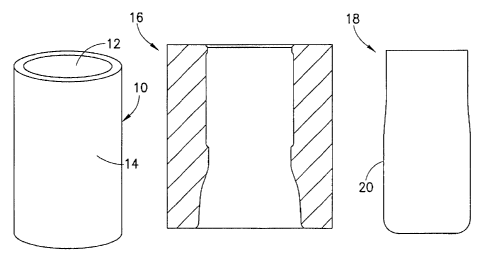
[0056] Figure 1 shows a die system 1 according to one embodiment of the
invention.
In this embodiment, the die system 1 comprises a metal container 10, a necking
die 16 and a
knockout 18. The metal container 10 has an opening 12 and a container side
wall 14. The
knockout 18 comprises a support surface 20.
[0057] Figure 2 illustrates the metal container 10 in more detail. The
metal
container 10 has a closed bottom forming a base 15. The container side wall 14
has a first
inner diameter 22 and a second inner diameter 24, wherein the first inner
diameter 22 of
the container side wall 14 is at least 0.001 inch greater than the second
inner diameter 24 of
the container side wall 14. The portion of the side wall 14 of the container
10 having the
first inner diameter 22 is referred to a thin wall 33. The portion of the side
wall 14 of the
container 10 having the second inner diameter 22 is referred to a thick wall
34. There is a
smooth transition 36 between the first inner diameter 22 of the container side
wall 14 and
the second inner diameter 24 of the container side wall 14 and also between
the thin wall
33 and the thick wall 34. In some embodiments, the first inner diameter 22 of
the container
side wall 14 is at least 0.0015 inch greater than the second inner diameter 24
of the
container side wall 14. In some embodiments, the first inner diameter 22 of
the container
side wall 14 is at least 0.002 inch greater than the second inner diameter 24
of the container
13
CA 02893366 2015-06-01
WO 2014/099496
PCT/US2013/074126
side wall 14. In some embodiments, the first inner diameter 22 of the
container side wall 14
is at least 0.0025 inch greater than the second inner diameter 24 of the
container side wall
14. In other embodiments, the first inner diameter 22 of the container side
wall 14 is at
least 0.003 inch greater than the second inner diameter 24 of the container
side wall 14. In
some embodiments, the first inner diameter 22 of the container side wall 14 is
at least 0.004
inch greater than the second inner diameter 24 of the container side wall 14.
In some
embodiments, the first inner diameter 22 of the container side wall 14 is at
least 0.005 inch
greater than the second inner diameter 24 of the container side wall 14.
[0058] As can be observed in the illustrated embodiment, the second inner
diameter
24 of the container side wall 14 is closer to the opening 12 of the metal
container 10 than
the first inner diameter 22 of the container side wall 14.
[0059] In some embodiments of the die system, the first inner diameter of
the
container side wall is no more than 0.006 inch greater than the second inner
diameter of
the container side wall. In some embodiments of the die system, the first
inner diameter of
the container side wall is no more than 0.005 inch greater than the second
inner diameter
of the container side wall. In some embodiments of the die system, the first
inner diameter
of the container side wall is no more than 0.004 inch greater than the second
inner
diameter of the container side wall.
[0060] The necking die 16, illustrated in Figure 3, has a working surface
26
comprising a land 28 a neck radius portion 40 and shoulder radius portion 42.
A relief 38 is
also shown. The land 28 is between the neck radius portion 48 and the relief
38. The inner
diameters of the neck radius portion 40 and the shoulder radius portion 42 are
greater than
the inner diameter of the land 28. The inner diameter of the land 28 is a
minimum diameter
of the necking die 16.
14
CA 02893366 2015-06-01
WO 2014/099496
PCT/US2013/074126
[0061] As
shown in Figure 4, the knockout 18 has a support surface 20. The support
surface 20 has a first knockout outer diameter 30 capable of supporting the
first inner
diameter 22 of the container side wall 14 when the knockout 18 is inserted
into the opening
12 of the metal container 10 and when the metal container 10 is being necked
with the
necking die 16; and a second knockout outer diameter 32 capable of supporting
the second
inner diameter 24 of the container side wall 14 when the knockout 18 is
inserted into the
opening 12 of the metal container 10 and when the metal container 10 is being
necked with
the necking die 16. As can be observed in Figure 4, the first knockout outer
diameter 30 is
larger than the second knockout outer diameter 32. However, the first knockout
outer
diameter 30 is capable of passing through the second inner diameter 24 of the
side wall 14
after necking when extracting the knockout 18 from the metal container 10.
Even though
the first knockout outer diameter 30 is larger than the second inner diameter
24 of the side
wall 14 after necking, the first knockout outer diameter 30 is capable of
passing through the
second inner diameter 24 of the side wall 14 after necking without damaging
the metal
container 10 because there will be a certain degree of spring-back in the side
wall 14 of the
metal container 10. The amount of spring-back will be determined by the
thickness,
temper, diameter of the container, and alloy of the metal comprising the metal
container
10. The first knockout outer diameter 30 is at least 0.001 inch greater than
the second
knockout outer diameter 24. In some embodiments the first knockout outer
diameter is at
least 0.0015 inch greater than the second knockout outer diameter. In some
embodiments,
the first knockout outer diameter is at least 0.002 inch greater than the
second knockout
outer diameter. In some embodiments, the first knockout outer diameter is at
least 0.0025
inch greater than the second knockout outer diameter. In some embodiments, the
first
knockout outer diameter is at least 0.003 inch greater than the second
knockout outer
CA 02893366 2015-06-01
WO 2014/099496
PCT/US2013/074126
diameter. In some embodiments, the first knockout outer diameter is at least
0.004 inch
greater than the second knockout outer diameter.
[0062] In some embodiments of the die system, the first knockout outer
diameter is
no more than 0.0060 inch greater than the second knockout outer diameter. In
some
embodiments of the die system, the first knockout outer diameter is no more
than 0.005
inch greater than the second knockout outer diameter. In some embodiments of
the die
system, the first knockout outer diameter is no more than 0.004 inch greater
than the
second knockout outer diameter.
[0063] As can be observed in Figures 5 and 6, the transition 36 between
the first
inner diameter 22 of the container side wall 14 and the second inner diameter
24 of the
container side wall 14 substantially matches the transition 39 between the
first knockout
outer diameter 30 and the second knockout outer diameter 32.
[0064] In operation of the die system 1, in Figure 1, to neck the metal
container 10,
according to one embodiment, the knockout 18 is inserted into the opening 12
of the metal
container 10. Then, the necking die 16 travels over the opening 12 of the
metal container
10. Figure 5 shows the knockout 18 inside the metal container 10, with the
necking die 16
about to slide over the metal container 10. As the necking die 16 travels over
the opening
12 of the metal container 10, the first knockout outer diameter 30 supports
the first inner
diameter 22 of the side wall 14 of the metal container 10 and the second
knockout outer
diameter 32 supports the second inner diameter 24 of the side wall 14 of the
metal
container 10, as shown in Figure 6. Then the necking die 16 is removed from
the metal
container 10. Finally, the knockout 18 is removed from the metal container 10,
wherein
when removing the knockout 18 from the metal container 10 the first knockout
outer
knockout diameter 20 passes through the second inner diameter 24 of the side
wall 14.
16
CA 02893366 2015-06-01
WO 2014/099496
PCT/US2013/074126
[0065] In some embodiments, the necking die 16 begins to travels over the
opening
12 of the metal container 10 after the knockout 18 begins to be inserted into
the metal
container 10 but before the knockout 18 is fully inserted into the metal
container 10.
[0066] In some embodiments, the necking die 16 begins to travels over the
opening
12 of the metal container 10 after the knockout 18 begins to be inserted into
the metal
container 10 but before the knockout 18 is fully inserted into the metal
container10. Once
the knockout 18 is fully inserted in to the metal container 10 it stops moving
while the
necking die 16 completes the end of its stroke and begins to move off of the
metal
container. Then the knockout 18 exits the metal container 10.
[0067] Alternative embodiments of a metal container 100 and a knockout
180 are
shown in Figures 7 and 8, respectively. The metal container 100 has a
container side wall
140 and the container side wall has a first inner diameter 220, a second inner
diameter 240
and a third inner diameter 250. The support surface 200 of the knockout 180
has a first
knockout outer diameter 300 capable of supporting the first inner diameter 220
of the
container side wall 140 when the knockout 180 is inserted into the opening 120
of the metal
container 100 and when the metal container 100 is being necked with a necking
die. The
support surface 200 of the knockout 180 also has a second knockout outer
diameter 320
capable of supporting the second inner diameter 240 of the container side wall
140 when
the knockout 180 is inserted into the opening 120 of the metal container 100
and when the
metal container 100 is being necked with a necking die. Finally, the support
surface 200 has
a third knockout outer diameter 325 capable of supporting the third inner
diameter 250 of
the container side wall 140 when the knockout 180 is inserted into the opening
120 of the
metal container 100 and when the metal container 100 is being necked with a
necking die.
17
CA 02893366 2015-06-01
WO 2014/099496
PCT/US2013/074126
[0068] Figure 9 shows the knockout 180 inside the metal container 100,
with a
necking die 160 about to slide over the metal container 100. In operation, as
the necking
die 160 travels over the opening 120 of the metal container 100, the first
knockout outer
diameter 300 supports the first inner diameter 220 of the side wall 140 of the
metal
container 100 and the second knockout outer diameter 320 supports the second
inner
diameter 240 of the side wall 140 of the metal container 100 and the third
knockout outer
diameter 325 supports the second inner diameter 250 of the side wall 140 of
the metal
container 100, as shown in Figure 10.
Examples
[0069] In one example embodiment, the thick wall portion of the metal
container is
0.006 inch thick and the thin wall portion of the metal container is 0.004
inch thick. In
another example, the thick wall portion of the metal container is 0.008 inch
thick and the
thin wall portion of the metal container is 0.006 inch thick. In a further
example, the thick
wall portion of the metal container, comprising a 211 can, is 0.0058 inch
thick and the thin
wall portion of the metal container is 0.0038 inch thick. In yet another
example, the thick
wall portion of the metal container is 0.006 inch thick and the thin wall
portion of the metal
container is 0.0038 inch thick. In a further example, the thick wall portion
of the metal
container is 0.0058 inch thick and the thin wall portion of the metal
container is 0.0048 inch
thick. In a final example, the thick wall portion of the metal container,
comprising a 211 can,
is 0.0063 inch thick and the thin wall portion of the metal container is
0.0041 inch thick.
[0070] While various embodiments of the present disclosure have been
described in
detail, it is apparent that modifications and adaptations of those embodiments
will occur to
those skilled in the art. However, it is to be expressly understood that such
modifications
and adaptations are within the spirit and scope of the present disclosure.
18
CA 02893366 2016-11-18
[0071] All features disclosed in the specification, including the claims,
abstracts, and
drawings, and all the steps in any method or process disclosed, may be
combined in any
combination, except combinations where at least some of such features and/or
steps are
mutually exclusive. Each feature disclosed in the specification, including the
claims,
abstract, and drawings, can be replaced by alternative features serving the
same, equivalent
or similar purpose, unless expressly stated otherwise. Thus, unless expressly
stated
otherwise, each feature disclosed is one example only of a generic series of
equivalent or
similar features.
19