Note: Descriptions are shown in the official language in which they were submitted.
CA 02893397 2015-06-01
METHOD AND DEVICE FOR GENERATING STEAM AND GASEOUS
HYDROGEN PEROXIDE
Field of the invention
The invention relates to the field of sterilization using hydrogen peroxide in
vapor or
gaseous form. More particularly, the invention relates to a method and device
for
generating hydrogen peroxide vapor in combination with the generation of
steam, which
is commonly required for sterilization purposes.
Background of the invention
Vaporized hydrogen peroxide (VHP ) is used for decontamination of enclosed and
sealed
areas. It is capable of destroying all forms of microbial life, including
bacteria, bacterial
spores, fungi, fungal spores, and viruses. It is commonly produced from a
solution of
liquid H202 and water, by means of generators specifically designed for the
purpose.
Aqueous hydrogen peroxide may be supplied as a 35 % stabilized solution, for
example
Vaprox supplied by Steris Corporation.
For producing hydrogen peroxide vapor, several methods have been developed and
suggested. In W02007003313 is disclosed the impingement of a spray of hydrogen
peroxide solution on a heat transfer surface to generate gaseous agent. This
has been said
to cause buildup of impurities on the heat transfer surface. According to US
5,258,162, a
spray of hydrogen peroxide solution may instead be introduced in a heated
carrier gas
stream which conveys the energy required for atomization. In EP 2 286 846 is
disclosed
how the atomization may be effected using ultrasound. In W02011076400, a flash
evaporator is disclosed having a series of wells in a heating block, into
which wells
hydrogen peroxide solution can be individually fed. A gas stream in a flow
channel above
the wells carries the total vaporized material from the series of wells to the
point of use.
In US patent 5,997,827 is disclosed a device having a porous tube section
which
hydrogen peroxide solution penetrates, vaporizing into a heated air stream
flowing to a
feed tube. The vaporizing section and the feed tube are steam heated.
CA 02893397 2015-06-01
2
In this context, "steam" refers to water in gaseous or condensing form.
"Vacuum" refers
to a pressure below atmospheric.
Certain products, e.g. products containing heat-sensitive biological material
in aqueous
solution or in dry form, require sterilization at relatively moderate
temperatures due to the
thermal sensitivity of the materials involved. Proteins, steroids and vaccine
components
are examples. In such cases, the use of vacuum, steam and hydrogen peroxide
vapor is
often an adequate solution. By means of pressure control, the temperature of
the steam
and the hydrogen peroxide vapor can be adjusted to a desired level. A lower
pressure
corresponds to a lower temperature in the steam and the hydrogen peroxide
vapor.
An apparatus for sterilization using a closed space in which goods are treated
with
hydrogen peroxide vapor requires, in addition to a source of hydrogen
peroxide, a source
of steam for heating the enclosure to which the load is confined to the
maximum
temperature allowed.
Summary of the invention
The present invention provides a combined source for heating steam and
vaporized
hydrogen peroxide. Also the carrier gas for the hydrogen peroxide may be
brought to the
correct temperature by means of a unit according to the invention.
The primary source of heat can be an electrical heating coil, or tubing
containing a circuit
with heat transfer medium as the skilled person may contemplate. According to
a first
aspect, a device according to the invention comprises a chamber adapted for
receiving
water through an inlet and expelling steam through an outlet, and a primary
heat source
associated with the chamber; preferably, this is the single heat source
involved. A vessel
for receiving and vaporizing hydrogen peroxide solution (in the following
denoted the
vessel) is provided in close contact with the chamber, although not
communicating with it
in the sense of allowing fluid transfer. Heat from the water vapor in the
chamber is
allowed to supply the required energy for producing hydrogen peroxide vapor in
the
vessel from an aqueous solution. The hydrogen peroxide vessel is integrated
with the
CA 02893397 2015-06-01
3
chamber so that at least part of the outer wall of the vessel forms part of
the inner walls
delimiting the chamber, whereby heat transfer occurs readily across the whole
of the
surface separating the interior of the chamber from the interior of the
vessel. The vessel is
embedded in the chamber so that the vessel is situated wholly in the steam
space, i.e.
above the water level during operation. Means are provided for preventing
contact of the
liquid water with the vessel. For example, one or more water level switches
may be
provided to control the water feed, to ensure that direct liquid water contact
with the
vessel outer surface does not occur. The level monitoring may be implemented
by any
technical means known to the skilled person, e.g.by floats, optical or
capacitive sensors,
or by an overflow arrangement. This arrangement ensures that the vaporization
surface
for hydrogen peroxide solution inside the vessel never reaches a temperature
above that
of steam at the pressure in the chamber.
Preferably, the surface mentioned above through which heat transfer occurs
(the heat
transfer surface) is dimensioned to transfer heat corresponding to at least
1/10 of the total
heating effect of the primary heat source. Preferably, the heat transfer
surface
corresponds to 1/10 to 1/5 of the total heating effect of the primary heat
source. More
preferably, the heat transfer surface corresponds to about 1/10 of the total
heating effect
of the primary heat source.
The capacity requirement for the primary heat source is determined by the size
of the
space used for sterilization in an apparatus served by the combined source for
heating
steam and vaporized hydrogen peroxide, and the pressure used. A space formed
by a
vacuum grade chamber of 2-4 m3 requires an effect of about 15 kW. For example,
a 3 m3
chamber may be served by a primary heat source of 15 kW, whereby the heat
transfer
capacity of the heat transfer surface is 1500 W. The capacity of the heat
transfer surface
is determined by material parameters. For example, stainless steel of 1 mm
thickness has
a heat transfer capacity of about 90 kW/m2.
The chamber is provided with an inlet for feed water and an outlet for steam,
as well as
an appropriate connection or connections for controlling the internal pressure
of the
chamber, i.e. a line connected to a vacuum source. Connections for temperature
and
pressure sensors and level control instrumentation are provided as required.
CA 02893397 2015-06-01
4
A closed conduit for carrier gas for vaporized hydrogen peroxide may pass
through the
chamber. This provides for bringing the carrier gas to the correct equilibrium
temperature
before it is conducted to the hydrogen peroxide vessel. The conduit ends in a
nozzle
within the vessel, in which is also provided an outlet for transporting
vaporized hydrogen
peroxide to the goods to be sterilized. A device designed according to the
principles set
out above has the capacity to generate a hydrogen peroxide concentration of at
least 2
mg/1 in the load space of a connected sterilization apparatus.
The vessel for receiving hydrogen peroxide solution is arranged in close
contact with the
chamber so that heat transfer from the water vapor in the chamber occurs
evenly over the
whole heat transfer surface of the vessel. Advantageously, the vessel is
embedded in the
chamber so as to form an integral part of the chamber structure.
The operating pressure of the device according to the invention may be in the
range 1
mbar ¨ 1000 mbar; the operating temperature may be in the range 20 - 120 C,
all
depending on the requirements of the sterilization schedule.
According to a further aspect of the invention, a method is provided for
supplying steam
and vaporized hydrogen peroxide to a sterilization apparatus using a single
heat source,
comprising the generation of steam within a first, essentially closed space
using a heat
source; conducting at least part of the generated steam to the sterilization
apparatus;
providing for heat transfer from the steam across a wall of said first
essentially closed
space to a second essentially closed space; conducting hydrogen peroxide
solution into
said second space to generate vaporized hydrogen peroxide by means of said
transferred
heat; and conducting vaporized hydrogen peroxide from the second space to the
sterilization apparatus. Preferably a carrier gas is conducted into said
second space to
facilitate the transfer of the vaporized hydrogen peroxide to the
sterilization apparatus.
Preferably, the carrier gas is preheated by conducting it in a closed conduit
through the
first space whereby it exchanges heat with the steam in the first space, and
preferably the
preheating leads to thermal equilibrium between the carrier gas and the steam.
"Essentially closed space" in this context means that fluid transfer to and
from the spaces
occurs only via connections provided for these purposes.
CA 02893397 2015-06-01
Brief description of the drawings
The invention is described in further detail in the following with reference
to the attached
drawings, in which
5 Figure 1 is a perspective drawing of a device according to the invention
Figure 2 is a sectional side view of a device according to the invention
Figure 3 is a schematic drawing of a device according to the invention
connected to a
jacketed chamber for sterilizing heat sensitive articles.
Detailed disclosure
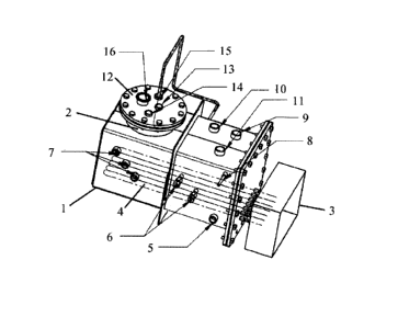
In Figure 1 is shown a device in accordance with the invention for the
simultaneous
generation of steam and hydrogen peroxide vapor. In the upper wall of chamber
1, which
here has the shape of a box, is provided an embedded vessel 2, here in the
shape of a
cylinder. The chamber is equipped with a heating unit which in the embodiment
shown is
an electrical unit 3 having heating coils 4 extending into the chamber near
its bottom
wall.
In the chamber, several inlets and outlets are provided. In the side wall
which is visible in
Figure 1 are water inlet 5, temperature probe connections 6 and water level
switch
connections 7. Further, carrier gas inlet 8 is shown. Some or all of these
connections
could be provided in the opposite side wall of the chamber if required.
In the top wall of the chamber are vacuum connection 9, steam outlet 10 and
vacuum
transmitter connection 11.
In the lid 12 of hydrogen peroxide vessel 2 are provided several in- and
outlet
connections.
Through inlet 13, hydrogen peroxide solution is fed into the vessel. The
vessel internal
pressure is adjusted through connection 14, connected to a vacuum line as
described
CA 02893397 2015-06-01
6
. .
below. Carrier gas enters the vessel through inlet 15, and the hydrogen
peroxide vapor is
led out via outlet 16.
Several of these features are also shown in Figure 2, in which the carrier gas
conduit, in
this embodiment in the form of a spiral coil 17, is visible.
During operation, feed water is supplied through inlet 5. It is heated by
means of primary
heat supplied by heating coils 4 to a temperature corresponding to its boiling
temperature
at the pressure determined by the vacuum generated within the chamber via
connection
14. The source of primary heat is electricity in the embodiment shown, but the
primary
heat may be supplied in any manner known to the skilled person, e.g. steam or
a heat
transfer medium. The water level is kept at a level below the bottom of
hydrogen
peroxide vessel 2, the level being controlled by level switches connected at
7. The upper
half of the chamber thus is a steam space held at the temperature required for
the
sterilization task at hand.
From this steam space, heating steam is conducted to a sterilization device as
described
below in connection with Figure 3. Within the steam space is the carrier gas
conduit in
the form of spiral coil 17. The length of the conduit is dimensioned according
to the
required flow of carrier gas to allow the gas stream to reach thermal
equilibrium with the
chamber before it enters the hydrogen peroxide vessel.
During operation, the hydrogen peroxide vessel is also in thermal equilibrium
with the
steam chamber, which supplies sufficient heat to produce the required flow of
vaporized
hydrogen peroxide. The hydrogen peroxide is dosed into the vessel through
inlet 13,
preferably not allowing any stagnant liquid to form in the vessel. The dosing
may be
carried out using a dosing pump from a storage flask.
Figure 3 shows the device of the invention as in Figure 2 schematically
connected to a
sterilization device 18, having an inner enclosure 19 for containing a load
for sterilization
and a jacket 20 for thermal control. The enclosure and the jacket are both
connected to a
vacuum source 21. Appropriate tubing also connects the vacuum source to the
steam
chamber and the hydrogen peroxide vessel. Control and shut-off valves for
controlling
the pressure in the various components of the apparatus are naturally provided
as the
CA 02893397 2015-06-01
, .
7
skilled person can contemplate, but these have been omitted for clarity in the
schematic
figure 3.
The whole apparatus being under computer control, it can be adapted for
sterilization
cycles according to the requirements of the relevant articles.
In the embodiment shown, the hydrogen peroxide vessel is a cylindrical body
embedded
in the upper wall of a box-shaped chamber for generating steam. The walls or
the bottom
of the vessel, or both, may be smooth or have a structure that extends the
heat transfer
area. Other shapes and other relative dimensions are possible as long as
proper heat
transfer is secured for keeping the hydrogen peroxide vessel in thermal
equilibrium with
the steam chamber during operation as well as a favorable flow route for the
carrier gas
and vaporized hydrogen peroxide.