Note: Descriptions are shown in the official language in which they were submitted.
METHODS AND APPARATUS FOR DOWNHOLE PROBES
Technical Field
[0001] This invention relates to subsurface drilling, specifically to drilling
operations
that use downhole probes. Embodiments are applicable to drilling wells for
recovering
hydrocarbons.
Background
[0002] Recovering hydrocarbons from subterranean zones relies on drilling
wellbores.
[0003] Wellbores are made using surface-located drilling equipment which
drives a
drill string that eventually extends from the surface equipment to the
formation or
subterranean zone of interest. The drill string can extend thousands of feet
or meters
below the surface. The terminal end of the drill string includes a drill bit
for drilling
(or extending) the wellbore. Drilling fluid usually in the form of a drilling
"mud" is
typically pumped through the drill string. The drilling fluid cools and
lubricates the
drill bit and also carries cuttings back to the surface. Drilling fluid may
also be used to
help control bottom hole pressure to inhibit hydrocarbon influx from the
formation
into the wellbore and potential blow out at surface.
[0004] Bottom hole assembly (BHA) is the name given to the equipment at the
terminal end of a drill string. In addition to a drill bit a BHA may comprise
elements
such as: apparatus for steering the direction of the drilling (e.g. a
steerable downhole
mud motor or rotary steerable system); one or more downhole probes;
stabilizers;
heavy weight drill collars; pulsers; and the like. The BHA is typically
advanced into
the wellbore by a string of metallic tubulars (drill pipe).
[0005] A downhole probe may comprise any active mechanical, electronic, and/or
electromechanical system that operates downhole. A probe may provide any of a
wide
range of functions including, without limitation, data acquisition, measuring
properties of the surrounding geological formations (e.g. well logging),
measuring
- 1 -
CA 2893467 2019-05-29
downhole conditions as drilling progresses, controlling downhole equipment,
monitoring status of downhole equipment, measuring properties of downhole
fluids
and the like. A probe may comprise one or more systems for: telemetry of data
to the
surface; collecting data by way of sensors (e.g. sensors for use in well
logging) that
may include one or more of vibration sensors, magnetometers, inclinometers,
accelerometers, nuclear particle detectors, electromagnetic detectors,
acoustic
detectors, and others; acquiring images; measuring fluid flow; determining
directions;
emitting signals, particles or fields for detection by other devices;
interfacing to other
downhole equipment; sampling downhole fluids; etc. Some downhole probes are
highly specialized and expensive.
[0006] Downhole conditions can be harsh. Exposure to these harsh conditions,
which
can include high temperatures, vibrations (including axial, lateral, and
torsional
vibrations), turbulence and pulsations in the flow of drilling fluid past the
probe,
shocks, and immersion in various drilling fluids at high pressures can shorten
the
lifespan of downhole probes and increase the probability that a downhole probe
will
fail in use. Supporting and protecting downhole probes is important as a
downhole
probe may be subjected to high pressures (20,000 p.s.i. [138 MN/m2] or more in
some
cases), along with severe shocks and vibrations. Furthermore, replacing a
downhole
probe that fails while drilling can involve very great expense.
100071 There are references that describe various centralizers that may be
useful for
supporting a downhole electronics package centrally in a bore within a drill
string.
The following is a list of some such references: US2007/0235224;
US2005/0217898;
US6429653; US3323327; US4571215; US4684946; US4938299; US5236048;
US5247990; US5474132; US5520246; US6429653; US6446736; US6750783;
US7151466; US7243028; US2009/0023502; W02006/083764; W02008/116077;
W02012/045698; and W02012/082748.
[0008] CA2735619 discloses snubber shock assemblies for measuring while
drilling
components that have natural frequencies that are less than a vibration
frequency of
an agitator.
- 2 -
CA 2893467 2019-05-29
PCT/CA2012/050885
CA 02893467 2015-06-01
30 September 2014 30-09-2014
[0009] US 5,520,246 issued May 28, 1996 discloses apparatus for protecting
instrumentation placed within a drill string. The apparatus includes multiple
elastomeric pads spaced about a longitudinal axis and protruding in directions
radially
to the axis. The pads are secured by fasteners.
[0010] US 2005/0217898 published October 6, 2005 describes a drill collar for
dampening downhole vibration in the tool-housing region of a drill string. The
collar
has a hollow cylindrical sleeve having a longitudinal axis and an inner
surface facing
the longitudinal axis. Multiple elongate ribs are mounted to the inner surface
and
extend parallel to the longitudinal axis.
[0011] There remains a need for better ways to provide downhole probes at
downhole
locations in a way that provides enhanced resistance to damage from mechanical
shocks and vibrations and other downhole conditions.
Summary
[0012] The invention has a number of aspects. One aspect of the invention
provides a
method for using a downhole probe. The method comprises providing a probe, at
least
one cross section of the probe having an area of at least pi inches squared
(approximately 20 cm2). The method further comprises inserting the probe into
a bore
of a drill collar and passing a drilling fluid through the bore of drill
collar at a flow
velocity of less than 41 feet per second (about 121/2 m/s).
[0013] In some embodiments, at least one cross section of the probe has an
area of at
least 3 inches squared (19 cm2) (at least 3 % inches squared [23 cm2] in some
embodiments). In some embodiments of the invention the probe is cylindrical
and has
an outside diameter of 2.54 inches (6 cm) and a total cross-sectional area of
5 inches
squared (32 cm2) (such a probe may, for example have a housing with an inside
diameter of 2 inches [5 cm]). In some embodiments such probes are deployed in
non-
standard drill collars having standard outside diameters and non-standard
extra large
inside diameters such that a desired area is maintained for the flow of
drilling fluid.
[0014] In some embodiments, the method comprises providing a probe comprising
an
electronics unit and a housing, and inserting the electronics unit into the
housing such
- 3 -
AMENDED SHEET
PCT/CA2012/050885
CA 02893467 2015-06-01
30 September 2014 30-09-2014
that at least a portion of the electronics unit forms a size-on-size fit with
the housing.
In some embodiments the entire length of the electronics unit forms a size-on-
size fit
with the housing. In some embodiments the electronics unit comprises a tubular
sleeve containing electronics. The electronics may be potted within the
sleeve. An
outer surface of the sleeve may be formed to have the desired size-on-size fit
in the
housing.
[0015] In some embodiments, the electronics unit is shaped like a cylinder and
the
housing is shaped like a hollow cylinder and the exterior diameter of the
electronics
unit is substantially equal to the interior diameter of the housing so that
there is
virtually no clearance for the electronics unit to move so as to bang against
the
housing and yet the electronics unit can still be slid into and out of the
housing. In
some embodiments the electronics unit and housing are dimensioned so as to
provide
a running fit between the electronics unit and the housing.
[0016] In some embodiments, the entire longitudinal surface of the electronics
unit is
dimensioned to form a size-on-size fit with the housing.
[0017] In some embodiments, the size-on-size fit prevents the electronics unit
from
moving laterally relative to the housing.
[0018] In some embodiments, a thin material is provided between an exterior
lateral
wall of the electronics unit and an interior lateral wall of the housing. In
some
embodiments there are no objects between the exterior lateral wall of the
electronics
unit and the interior lateral wall of the housing.
[0019] In some embodiments, the housing has a length to outer diameter ratio
of 60:1.
In some embodiments the housing is less than 20 feet (6 m) or 13 feet long (4
m).
[0020] In some embodiments, the method comprises mechanically coupling the
housing to the collar. The mechanical coupling may couple rotationally
(torsionally)
or radially (laterally) and preferably couples the housing to the collar both
radially
and rotationally. The probe may be supported along all or substantially all of
the full
length of the housing in some embodiments.
- 4 -
AMENDED SHEET
PCT/CA2012/050885
CA 02893467 2015-06-01
30 September 2014 30-09-2014
[0021] In some embodiments, the method comprises providing a centralizer,
inserting
the electronics package into the centralizer, and inserting the centralizer
into the bore
of the collar.
[0022] In some embodiments, the centralizer comprises an elongated tubular
member
having a wall formed to provide a cross section that provides first outwardly-
convex
and inwardly-concave lobes, the first lobes arranged to contact an internal
wall of the
collar at a plurality of spots spaced apart around an internal circumference
of the
collar; and a plurality of inwardly-projecting portions, each of the plurality
of
inwardly-projecting portions arranged between two adjacent ones of the
plurality of
first lobes.
[0023] In some embodiments the centralizer comprises a tubular member having a
wall extending around the probe, the wall formed to contact an internal wall
of the
collar and an outside surface of the housing, a cross section of the wall
following a
path around the probe that zig zags back and forth between the outside surface
of the
housing and the internal wall of the collar.
[0024] Another aspect of the invention provides downhole probes.
[0025] Another aspect of the invention provides downhole assemblies configured
for
supporting downhole probes. The downhole assemblies may include downhole
probes.
[0026] Further aspects of the invention and features of example embodiments
are
illustrated in the accompanying drawings and/or described in the following
description.
Brief Description of the Drawings
[0027] The accompanying drawings illustrate non-limiting example embodiments
of
the invention.
[0028] Figure 1 is a schematic view of a drilling operation according to one
embodiment of the invention.
- 5 -
AMENDED SHEET
[0029] Figure 2A is a schematic view of a probe known in the prior art.
Figures 2B
and 2C are respectively longitudinal and vertical cross sections of the probe
in Figure
2A.
[0030] Figure 3A is a schematic view of a probe according to one embodiment of
the
invention. Figures 3B and 3C are respectively longitudinal and vertical cross
sections
of the probe in Figure 3A.
[0031] Figure 4 is a perspective cutaway of a downhole assembly containing an
electronics package.
[0032] Figure 4A is a view taken in section along the line 4A-4A of Figure 4.
[0033] Figure 4B is a perspective cutaway view of a downhole assembly not
containing an electronics package.
[0034] Figure 4C is a view taken in section along the line 4C-4C of Figure 4B.
[0035] Figure 5 is a schematic illustration of one embodiment of the invention
where
an electronics package is supported between two spiders.
[0036] Figure 5A is a detail showing one assembly for anchoring a downhole
probe
against longitudinal movement.
[0037] Figure 5B is an exploded view showing one way to anchor a centralizer
against rotation in the bore of a drill string. The anchor may also support
the
centralizer against longitudinal movement.
[0038] Figure 6 is a perspective view of a centralizer according to one
embodiment of
the invention.
[0039] Figure 6A is a view taken in section along the line 6A-6A of Figure 6.
[0040] Figure 7 is a view of the same structure in Figure 4A, but with the
electronics
package only partially inserted.
- 6 -
CA 2893467 2020-03-10
PCT/CA2012/050885
CA 02893467 2015-06-01
30 September 2014 30-09-2014
Description
[0041] Figure 1 shows schematically an example drilling operation. A drill rig
10
drives a drill string 12 which includes sections of drill pipe that extend to
a drill bit
14. The illustrated drill rig 10 includes a derrick 10A, a rig floor 10B and
draw works
10C for supporting the drill string. Drill bit 14 is larger in diameter than
the drill
string above the drill bit. An annular region 15 surrounding the drill string
is typically
filled with drilling fluid. The drilling fluid is pumped by a pump 15A through
a bore
in the drill string to the drill bit and returns to the surface through
annular region 15
carrying cuttings from the drilling operation. As the well is drilled, a
casing 16 may
be made in the well bore. A blow out preventer 17 is supported at a top end of
the
casing. The drill rig illustrated in Figure 1 is an example only. The methods
and
apparatus described herein are not specific to any particular type of drill
rig.
[0042] Drill string 12 includes a downhole probe 22. Probe 22 may comprise any
sort
of downhole probe, some examples of which are described above. Drill string 12
may
contain more than one downhole probe 22.
[0043] Damage to a downhole probe is especially likely when a resonant
vibrational
mode of the downhole probe is excited. External vibrations at or near the
frequency of
a vibrational mode of a downhole probe can cause the probe to experience large
amplitude resonant vibrations. These vibrations may be severe enough to break
internal components of the probe and/or cause the probe to impact against
adjacent
surfaces and/or to weaken components of the probe. The present invention
provides
several features that may be beneficially combined in a downhole probe system
but
also have application individually and in sub-combinations. These features can
be
applied to make downhole probes more tolerant of downhole conditions and less
prone to failure.
[0044] As noted above, the downhole environment is very challenging to
mechanical
structures. Interaction between the rotating drill bit and the formation being
drilled
into results in significant vibration. Since the drill bit is typically
significantly larger
in diameter than the drill string sections uphole from the drill bit the drill
string
sections can move, sometimes with significant accelerations from side-to side
within
the bore hole. Flowing drilling fluid is an additional source of vibrations.
Variations
- 7 -
AMENDED SHEET
PCT/CA2012/050885
CA 02893467 2015-06-01
30 September 2014 30-09-2014
in the flow and turbulence in the flow can apply significant mechanical forces
to
downhole probes. The frequency spectrum of downhole vibrations tends to be
dominated by low-frequency vibrations. For example, rotation of a drill bit at
300
RPM (5 Hz) may lead to a vibration frequency spectrum having a peak at about 5
Hz
that drops off fairly significantly at higher frequencies. In most drilling
situations drill
bits are rotated at speeds slower than 300 RPM. Rotation of drill bits at
lower rates of
revolution (e.g. 120 RPM to 200 RPM) may lead to a frequency spectrum of
downhole vibration that peaks at still lower frequencies (e.g. 2 Hz to 3.33
Hz) and
drops off significantly at higher frequencies.
[0045] The inventors have noted that accelerations of components within a
downhole
probe can be magnified significantly if the downhole probe has a vibration
mode that
coincides with a frequency of the vibration to which the downhole probe is
exposed
such that the dovmhole probe (or a part thereof) undergoes resonant vibration.
Acceleration of the downhole probe and its components can be magnified further
still
if the downhole probe is caused to move in such a manner that it bangs into
another
structure (e.g. a wall of a drill collar). Such banging is particularly bad
where a hard
surface of the downhole probe impacts against another hard surface. Such
impacts can
cause 'pinging' (high amplitude, high frequency vibrations) that can be very
damaging to electronics, wiring, and other sensitive devices.
[0046] Various previous devices have attempted to address the general problem
that
large accelerations can be damaging to downhole probes, especially when
repeated.
Since it is given that drill string sections will be subjected to large
accelerations when
used under typical downhole conditions some prior art devices have attempted
through the use of various mechanisms to isolate downhole probes from
vibration by
providing rubber or similar cushioning elements between the downhole probe and
the
drill string sections through which the downhole probe passes. The present
inventors
have determined that such cushioning/isolation can be counterproductive
because
allowing the downhole probe to move with respect to the drill string sections
to
reduce transmission of vibrations to the downhole probe often makes the
downhole
probe susceptible to experiencing even more damaging motions resulting from
excitation of resonant modes of the downhole probe and impacts between the
downhole probe and other structures.
- 8 -
AMENDED SHEET
PCT/CA2012/050885
CA 02893467 2015-06-01
30 September 2014 30-09-2014
[0047] Described herein are a number of constructions that are advantageously
applied in combination with one another but can also be used individually or
in sub-
combinations with one another or with other known apparatus. In some
embodiments
a downhole probe is mechanically tightly coupled to one or more drill string
sections
through which it extends. While such coupling does expose the downhole probe
to the
vibration of the drill string sections the coupling can raise the resonant
frequency of
the downhole probe sufficiently to make such vibrations less damaging than
they
would otherwise be. This can be achieved while maintaining the downhole probe
centered in the drill string which is convenient for certain types of
measurements.
[0048] In some embodiments the downhole probe is increased in diameter
relative to
prior comparable downhole probes. Such increased diameter also tends to
increase the
stiffness of the downhole probe and to increase the frequencies of vibrational
modes
of the downhole probe. Use of a downhole probe having an increased diameter in
a
drill string made of standard drill collars while maintaining sufficient
passage for
drilling fluid would be impossible for at least some sizes of drill collar. In
some
embodiments, the use of such larger-diameter downhole probes is facilitated
through
the use of non-standard drill collars having standard outside diameters but
increased
bore diameters. Such non-standard drill collars may be made of high strength
materials so that they provide strength equivalent to that of the standard
drill collars
.. they replace.
[0049] Increasing the diameter of a downhole probe can provide increased
internal
volume. This, in turn facilitates packing more electronics or other components
into
each length of the downhole probe. Consequently the downhole probe may be made
shorter than comparable prior art probes. This length reduction is compounded
by the
fact that downhole probes are typically made up of a number of sections
coupled
together by couplings. The active components housed in such probes are divided
among the sections. Typically each added coupling necessitates wire harnesses
and
associated electrical couplings to carry electrical power and signals between
the
sections as well as added mechanical parts to support the active components.
Each
coupling typically has a significant length that is not available for
electronics or other
components. Packing more functionality into each length of the probe reduces
the
number of sections needed to provide functionality which, in turn, reduces the
number
- 9 -
AMENDED SHEET
PCT/CA2012/050885
CA 02893467 2015-06-01
30 September 2014 30-09-2014
of couplings needed, which, in turn reduces the overall length of the probe.
The
reduced length, in turn, tends to increase the frequency of vibrational modes
of the
probe.
[0050] In some embodiments the probe is internally constructed such that there
is a
size-on size fit between internal components of the probe and a housing of the
probe.
Such construction couples the internal components to move with the probe and
can
improve reliability.
100511 Features as described herein relate to the following aspects of probe
systems:
internal construction of probes; probe form factors; drill collar dimensions
and
construction; and mounting of probes within the drill string.
[0052] Downhole probes are generally supported within the bore of one or more
drill
collars. Probes are typically long and thin so that they can fit within the
bores of
standard API drill collars while leaving enough room for drilling fluid to
flow around
the probe. The cross-sectional area made available for the flow of drilling
fluid around
the probe should also be large enough that the velocity of drilling fluid
flowing past
the probe is not excessive. Excessive flow velocities can lead to cavitation
which can
damage both the probe and the drill collars in which the probe is mounted. It
is
generally accepted that the flow velocity of drilling fluid should be
maintained below
41 feet/sec (about 121/2 m/s).
TABLE I ¨ Some Example Drill Collar Dimensions According to
API Specification 7 / 7-1.
Collar OD Collar ID
(inches) (cm) (inches) (cm)
31/8 8 1 _ 3
31/2 9 1'/2 4
41/8 10 2 5
4% 12 2 6
5 13 2'/4 6
6 15 2 6
6 15 213/16 7
6 16 2 6
6 16 213/16 7
6% 17 2 6
6'/2 17 213/16 7_
- 10 -
AMENDED SHEET
63A 17 2 6
7 18 2 6
7 18 213/16 7
7 18 213/16 7
8 20 213/16 7
8 20 3 8
8 21 213/16 7
91/2 24 3 8
93/4 25 3 8
10 25 3 8
11 28 3 8
[0053] Drill collars may be drilled to increase the internal bore diameter.
However,
increasing the internal diameter more than a small amount would result in the
drill
collar being excessively weakened and unsuitable for use. For example, a
standard 43/4
(12cm) drill collar can be bored out from 2 'A to 2 11/16 inches (6 cm to 7
cm); a
standard 8 inch (20 cm) OD drill collar can be bored out from 3 inches to 31/4
inches
(7.6 cm to 8.3 cm).
[0054] A downhole probe 22 typically comprises a protective housing. A probe
housing may comprise a hollow cylindrical tube with closed ends. Active
components
of the probe (e.g. batteries, sensors, electronics, telemetry signal
generators, etc.) are
housed in a chamber within the probe housing. A probe housing may be made of
any
suitable material. Two examples of materials suitable for use as a probe
housing are
suitable stainless steels and beryllium copper.
[0055] Figure 2A shows schematically a probe 21 comprising a housing 21A and
an
electronics unit 21B supported within housing 21A. Electronics unit 21B
comprises a
support structure which carries electronics components. Electronics unit 21B
is
smaller in diameter than an inner diameter of housing 21A. Shock rings 21C are
spaced apart along electronics unit 21B. Shock rings 21C extend around
electronics
unit 21B and bear against the inner wall of probe housing 21A. Shock rings 21C
maintain a gap 21D between electronics unit 21B and the inner wall of probe
housing
21A. Figures 2B and 2C are respectively longitudinal and vertical cross
sections of
downhole probe 21.
- 11 -
C A 2893467 2019-05-29
PCT/CA2012/050885
CA 02893467 2015-06-01
30 September 2014 30-09-2014
[0056] It is widely accepted in the industry that a probe construction that
includes
shock rings 21C is necessary to protect electronics unit 21B from vibrations
and
shocks in the downhole environment.
[0057] Figure 3A shows schematically a downhole probe 31 according to an
example
embodiment. Probe 31 comprises a probe housing 31A and an electronics unit 31B
supported within housing 31A. In contrast to prior art probe 21, electronics
unit 31B
of downhole probe 31 has an outer diameter which is substantially equal to the
inner
diameter of housing 31A. Thus electronics unit 31B and probe housing 31A have
a
"size-on-size" fit. The external surface of electronics unit 31B is in
intimate contact
with the inside of housing 31A and therefore cannot move relative to housing
31A.
[0058] In some embodiments, electronics unit 31B comprises components
(electronic,
mechanical, or otherwise) (not shown) mounted within a support structure (not
shown). The support structure may comprise a carbon fiber tube, for example.
The
support structure may be manufactured with an external diameter substantially
equal
to the interior diameter of housing 31A. The components may be potted within
the
support structure by a potting agent (e.g. epoxy, Dow Corning Sylgard 184,
etc.).
[0059] Electronics unit 31B may be inserted into or removed from probe housing
31A
by opening housing 31A (e.g. by removing a cap at one end of housing 31A or
separating housing 31A into two parts at a joint) and sliding electronics unit
31B into
or out of probe housing 31A. A lubricant may be used to ease insertion.
Figures 3B
and 3C are longitudinal and vertical cross sections, respectively, of an
example
downhole probe 31.
[0060] It is not mandatory that the outer surface of the electronics unit be
in direct
contact with the probe housing. In some embodiments a thin layer of material
may be
provided between electronics unit 31B and probe housing 31A. This layer of
material
may be bonded to electronics unit 31B or to probe housing 31A or may comprise
a
tubular sleeve. The layer of material may advantageously have vibration
damping
properties that tend to reduce transmission of high-frequency vibrations to
electronics
unit 31B. For example, the layer of material may comprise a thin sleeve or
coating of
rubber, a suitable elastomer, a plastic or the like. The material of the layer
may be
- 12 -
AMENDED SHEET
PCT/CA2012/050885
CA 02893467 2015-06-01
30 September 2014 30-09-2014
resiliently compressible to provide some cushioning for probe 31 while still
providing
full-length size-on-size mechanical coupling between electronics unit 31B and
probe
housing 31A. Where such a layer of material is provided, it is generally
desirable that
the layer of material fills the gap between electronics unit 31B and probe
housing 31A
and extends substantially the full length of electronics unit 31B.
[0061] The thin layer of material may optionally be electrically conductive or
electrically-insulating. In some embodiments the layer of material comprises
two or
more electrically conductive parts separated by electrically insulating parts.
[0062] In some alternative embodiments, electronics unit 31B forms a size-on-
size fit
with housing 31A for only part of the length of housing 31A. In some
embodiments,
only 99%, 95%, 90%, 80%, or 50% of the outer lateral surface of electronics
unit 31B
forms a size-on-size fit with the inner wall of probe housing 31A.
[0063] In some embodiments, electronics unit 3111 comprises a plurality of
distinct
modules. The modules may be coupled together with one another or separate. In
such
embodiments, one or more of the modules of the electronics unit may form a
size-on-
size fit within probe housing 31A. In some embodiments probe 31 comprises a
plurality of coupled-together sections. Each section may comprise an
electronics unit
31B mounted within a probe housing 31A.
[0064] In the illustrated embodiment, probe 31 is cylindrical in form (i.e.
its cross
sections are circles). In other embodiments, probe 31 may have cross sections
of other
shapes, such as oval or polygonal. In some embodiments, the cross section of
the bore
of probe housing 31A has a round or non-round shape which corresponds to the
cross-
sectional shape of electronics unit 31B to allow for a size-on-size fit
between
electronics unit 31B (or other active components housed within probe 31) and
probe
housing 31A.
[0065] In probe 31, there is no lateral gap between probe electronics unit 31B
and
probe housing 31A. This structure prevents lateral movement of electronics
unit 31B
relative to probe housing 31A, and thereby prevents electronics unit 31B from
striking
probe housing 31A with any significant velocity.
- 13 -
AMENDED SHEET
[0066] Electronics unit 31B is mechanically coupled to probe housing 31A by
the
size-on-size fit between these components. This mechanically-coupled
structure, by
virtue of its increased stiffness, has a higher resonant frequency than either
of its
component parts. Additionally, since electronics unit 31B is prevented from
moving
within probe housing 31A, probe housing 31A and electronics unit 31B cannot
accelerate significantly with respect to one another and collide.
Consequently, probe
31 may be less susceptible to damage from the low frequency vibrations which
typically accompany drilling operations than a prior downhole probe of the
type
illustrated in Figures 2A to 2C.
[0067] By contrast, in probe 21, electronics unit 21B has unsupported portions
21E
between shock rings 21C. If housing 21A is subjected to vibrations then
vibrations
will be transferred through shock rings 21C to electronics unit 21B, thereby
inducing
vibration of electronics unit 21B. If either housing 21A or electronics unit
21B is
made to vibrate at or near a resonant frequency then the amplitude of the
vibration
may become relatively large, increasing the likelihood of damage to probe 21.
Unsupported portions 21E of electronics unit 21B may vibrate with different
frequencies, phases, or amplitudes than probe housing 21A. Thus unsupported
portions 21E may experience vibrations of significant amplitudes. Such
vibrations
may harm unsupported portions 21E and may also cause unsupported portions 21E
to
flex enough that they impact housing 21A. Further, since shock rings 21C are
very
thin, they tend to transfer shocks to electronics unit 21B. Electronics unit
21B may, in
some circumstances, suffer damage from such vibrations and impacts.
[0068] The construction of probe 31 may provide one or more of the following
benefits:
= Providing a size-on-size fit between electronics unit 31B and probe housing
31A eliminates the need for shock rings 21C or similar apparatus. This may
reduce manufacturing, service, and maintenance costs.
= The construction of probe 31 without shock rings 21C may also simplify
assembly of probe 31.
= Probe 31 has no shock rings 21C and so cannot be harmed by failure of one or
more shock rings 21C.
- 14 -
CA 2893467 2020-03-10
= The size-on-size fit allows housing 31A to provide continuous support to
electronics unit 31B up-to its entire length. Housing 31A may thereby act to
reduce localized bending of electronics unit 31B.
= Since probe 31 has no gap 21D probe 31 can accommodate more electronics
or other equipment than could fit in a probe 21 having the same housing
dimensions. Use of the internal volume of probe 31 may be more efficient than
could be achieved with a longer, thinner electronics unit.
= The frequencies of vibrational modes of the probe are increased as a
result of
mechanical coupling between the housing 31A and electronics package 31B.
= The close tolerance fit between electronics unit 31B and housing 31A may be
made even tighter as a result of external pressure downhole, thereby locking
electronics unit 31B and housing 31A together.
= Electronics unit 31B and probe housing 31A cannot bang into one another
because they cannot move relative to one another.
= The material of housing 31A may be thinner in some embodiments than would
otherwise be required to resist downhole pressures as it is internally-
supported.
[0069] Downhole probes are typically required to be small in diameter so that
they do
not obstruct too much of the cross-sectional area of the bore of the drill
string in
which they are located. Standard drill collars of the type often used in
drilling
wellbores have bore diameters in the range of 2 1/4 inches to about 31/2
inches (6 cm to
9 cm). Table I provides dimensions of some example standard drill collars.
These
dimensions provide appropriate strength for typical drilling operations and
have been
established based on many years of industry experience.
[0070] In order to fit into the bores of standard drill collars while still
leaving
adequate space for the flow of drilling fluid, a typical downhole probe must
have an
outside diameter of less than 2 inches (5 cm) (for example downhole probes
having
diameters of 1 1/4 inches [3 cm], 1 1/4 inches [4 cm] or 1 7/8 inches [5 cm]
are
commonly used). A downhole probe of a larger diameter would result in a small
cross
section for passage of drilling fluid which, in turn would result in fluid
velocities
exceeding 41 feet/sec (about 12 1/2 m/s) at typical flow rates required for
drilling. The
- 15 -
CA 2893467 2019-05-29
PCT/CA2012/050885
CA 02893467 2015-06-01
30 September 2014 30-09-2014
required flow rates tend to increase for larger-diameter drill bits. Table II
provides
some example flow rates.
TABLE I I¨ EXAMPLE FLOW RATES
External Cross sectional Typical required flow Cross sectional area
Diameter area of bore rate (US Gallons per required to provide
flow
(Inches) Minute) rate with velocity less
than 41 feet/sec
(about 12 1/2 m/s)
4 % 5.7 in2 (37 cm2) <350 (<22 1/s) 2/4 in2 (18 cm2)
6 1/2 6.2 in2 (40 cm2) <550 (<34 Vs) 5.3 in2 (34 cm2)
8 8.3 in2 (54 cm2) <1100 (<68 Ifs) 10.6 in2 (68 cm2)
100711 Probes according to some embodiments of the invention are significantly
larger in diameter than prior art probes. For example, in some embodiments, a
probe
31 has a probe housing 31A that has an outer diameter of more than 2 inches (5
cm).
As an example, in some embodiments, housing 31A has an outer diameter of 2.54
inches (6 cm). Increasing the diameter of the probe by even a small amount can
very
significantly increase the overall stiffness of the probe since stiffness of a
member
(e.g. a probe housing) tends to increase with a higher power (e.g. the cube)
of the
diameter with all other factors equal. Further, as explained elsewhere in this
disclosure, such larger-diameter probes may be used in drill string sections
that have
relatively small diameters while still maintaining sufficient cross-sectional
area
around the probe for the flow of drilling fluid past the probe at suitably
high rates for
drilling and at suitably low flow velocities. This may be achieved, for
example by
supporting probes in thinner-walled drill string sections of high-strength
materials.
Such probes may be used in drill string sections having outer diameters of a
wide
- 16 -
AMENDED SHEET
PCT/CA2012/050885
CA 02893467 2015-06-01
30 September 2014 30-09-2014
range of sizes from, for example 4 1/4 inches (12 cm) or less up to larger
sizes such as
8 (20 cm), 11(28 cm) or 13 (33 cm) inches or more.
[0072] Increasing the diameter of the probe also significantly increases the
volume
within the probe for each unit of length of that probe. The increased cross-
sectional
area available for active components of the probe also tends to allow a much
more
volumetrically-efficient arrangement of components within the probe with
significantly less wasted volume.
[0073] As noted above, a diameter of 2 inches (5 cm) or more can result in the
probe
obstructing too much of the bore of a standard-sized drill collar (e.g. a
drill collar
having dimensions as specified by the API standards) to maintain flow
velocities
below 41 feet/sec (about 12 1/2 m/s). In some embodiments this is addressed by
providing drill collars for use in conjunction with the probes that have
standard
outside diameters but walls that are thinner than those of standard drill
collars such
that, for a given outside diameter the drill collar has a larger area bore
than the
standard collar of the same outside diameter. The thin-walled drill collars
may be
made to have strength equal to or exceeding that of standard drill collars
while
exhibiting required bending strength and bending strength ratios at
connections to
other drill string sections.
[0074] Strong drill string sections having larger than standard bores and
standard or
near-standard outside diameters may be achieved by fabricating the thin-wall
drill
collars of high strength materials. For example, standard drill collars are
often made
from steel that has a yield strength of 110,000 psi (765 MN/m2). A thin-walled
collar
may be made of high-strength steel (such as a high strength non-magnetic
stainless
steel alloy) having a yield strength of 130,000 psi (896 MN/m2) or more (e.g.
140,000
psi L965 MN/m2] or 160,000 psi [1103 MN/m2]) such that the collar meets or
exceeds
the strength of the standard drill collar, has an outside diameter that
matches that of
the standard drill collar and yet, due to the reduced wall thickness, provides
a bore
large enough to accommodate a large diameter probe and still leave a large
enough
cross-section of the bore available for carrying drilling fluid. The cross
section
available for carrying drilling fluid may exceed that of standard collars
using smaller
- 17 -
AMENDED SHEET
PCT/CA2012/050885
CA 02893467 2015-06-01
30 September 2014 30-09-2014
diameter probes in some embodiments. Table III provides some example
dimensions
for drill collars with standard outside diameters and extra-large inside
diameters.
TABLE III ¨ SOME EXAMPLE NON-STANDARD DRILL COLLAR
DIMENSIONS
External Diameter (inches) Internal Diameter (inches)
(13 cm) 3.63 (9 cm)
(compatible with 4 3/4 (12 cm) drill
collars)
6 5/8 (17em) 4.5 (11 cm)
8 (20 cm) 6 3/64 (15 cm)
9 (23cm) to 10 (25 cm) 6 % (17 cm) or greater
[0075] A section of drill collar for use with a probe may, in addition to
having a non-
5 standard larger bore size, have one or more features for supporting the
probe. For
example, the drill collar section may comprise one or more landing steps or
other
features for holding the probe axially in the bore of the drill collar. Such a
drill collar
may optionally have one or more transition sections which smoothly reduce the
bore
diameter of the drill collar to match the bore of standard drill collars that
may be
coupled to the drill collar at one or both ends.
[0076] In order to fit the required systems inside a small-diameter form
factor,
downhole probes typically have very large ratios of length to diameter. For
example,
length-to-diameter ratios far exceeding 100:1 are not uncommon. Some downhole
probes are, for example, 1.875 (5 cm) or 1.75 (4 cm) inches in diameter and
approximately 30 feet (9 m) or more in length. A probe with such dimensions is
quite
fragile. Such a probe may be damaged during handling. It may also be damaged
by
the harsh downhole environment, particularly by resonant vibrations, including
those
- 18 -
AMENDED SHEET
caused by the flow of drilling fluid past the probe and stick-slip shocks from
drilling
which may present accelerations having lateral, axial, and torsional
components.
100771 In some embodiments the probes have much smaller ratios of length to
diameter than prior art probes. In some such embodiments the ratio of length
to outer
diameter for the probe is 70:1 or less. For example, in an example embodiment,
probe
housing 31A is approximately 2 1/2 inches (6 cm) in diameter and approximately
13
feet (4 m) long. In an example embodiment a length to diameter ratio of the
probe is
60:1. Making a probe larger in diameter can permit making the probe shorter
while
providing the same functionality. A shorter probe tends to have a greater
effective
.. stiffness all other factors being equal (since the frequencies of
transverse vibrational
modes depends on both length and stiffness these frequencies can be caused to
increase by making the probe shorter, making the probe stiffer ¨ making the
probe to
have a higher elastic modulus ¨ or both). Making a probe shorter and larger in
diameter tends to raise the frequencies of vibrational modes of the probe
which, in
turn tends to reduce the amplitude of vibrations induced in the probe by the
predominantly low-frequency vibrations resulting from drilling operations.
100781 In some embodiments the probe is constructed so that the frequencies of
its
lowest-frequency vibrational modes are well in excess of 4 to 10 Hz where
downhole
vibrations tend to have maximum amplitudes. For example, the frequency of a
first
.. fundamental (F1) vibration mode of the probe when pinned at its ends may be
in
excess of 20 Hz. The frequency may be further increased by mechanically
coupling
the probe to the drill string, as described below. Achieving a probe that does
not have
low-frequency vibrational modes that would be resonantly excited by low-
frequency
downhole vibrations may be achieved by one or more of: making the probe
shorter,
making the probe larger in diameter (stiffer), making the contents of the
probe a size-
on-size fit with the probe housing (which makes the probe stiffer), using a
centralizer
to mechanically couple the probe to the drill collar and supporting the probe
in the
drill collar with two or more supports that hold the probe against axial
and/or
transverse motion (for example by spiders or other supports at each end of the
probe ¨
such supports can be particularly effective where one or both supports hold
the
supported portion of the probe parallel to a centerline of the drill string
section in
- 19 -
CA 2893467 2019-05-29
PCT/CA2012/050885
CA 02893467 2015-06-01
30 September 2014 30-09-2014
which the probe is supported). In some embodiments the probe has a length not
exceeding 30 feet (9 m) and a diameter of more than 1.875 inches (5 cm).
[0079] Further increases in the frequencies of vibrational modes may be
achieved by
mechanically coupling the probe to the drill string section(s) through which
it passes
(which tends to make the probe effectively stiffer). Such mechanical coupling
advantageously is provided for an extended distance along the length of the
probe in
which case the mechanical coupling can additionally be effective at
suppressing
vibrational modes by restraining possible motions of the probe. Such coupling
can be
especially effective at suppressing a fundamental transverse vibrational mode
and its
lower harmonics (e.g. Fl, F2, F3). With such structures, the frequencies of
vibrational
modes that could possibly be excited with energies sufficient to make damage
to the
probe likely can be made to be significantly higher than the low frequency
(e.g. 1-
10Hz) vibrations that are predominant in the downhole environment. In some
embodiments, the frequencies of the third and higher vibrational modes (F3 and
up) of
a probe are all in excess of 10 Hz. In some embodiments, the frequencies of
the third
and higher vibrational modes (F3 and up) of a probe are all in excess of 40
Hz.
[0080] Although based on assumptions (such as uniform mass per unit length)
that
may not be precisely satisfied by a real probe, the following formula provides
a useful
indication regarding how changes to the geometry of a probe can affect the
frequency
of transverse vibrational modes of the probe:
2 El _ 2 El
on= fin pA=GenL)
pAL4
In this formula, L is the length of the probe, A is the cross-sectional area
of the probe,
p is the mass density of the probe, E is the elastic modulus of the probe, I
is the
moment of inertia of the probe, I3n is the wavenumber for vibrations in the
nth mode
and on is the frequency of vibrations in the nth mode.
[0081] Similar calculations may be performed to determine natural frequencies
of
torsional vibrations of the probe. These frequencies depend on the torsional
stiffness
- 20 -
AMENDED SHEET
PCT/CA2012/050885
CA 02893467 2015-06-01
30 September 2014 30-09-2014
of the probe as well as its moment of inertia. Torsional stiffness increases
rapidly with
increases in probe diameter. As with transverse vibrational modes, making a
probe
larger in diameter and shorter can significantly increase the natural
frequencies of
torsional modes. Mechanically coupling the probe to a drill string section in
a manner
that resists rotation of the probe relative to the drill string section can
further increase
the natural frequencies of such torsional modes.
[0082] Short and wide probes may provide one or more of the following
benefits:
= They may be less susceptible to damage than conventional probes which
have
small cross sections and long lengths. For example, they may have increased
resonant frequencies and thus may be less susceptible to damage caused by
low frequency vibrations.
= They may be easier to transport due to their decreased length.
= They may have fewer probe separation points, and thus they may require
fewer intersectional connectors and mechanical fixtures. Some short probes
may require no intersectional connectors or mechanical fixtures at all.
= Reducing the number of couplings between different probe sections reduces
the number of electrical interconnections between different probe sections
(such electrical interconnections are vulnerable to failure and so eliminating
electrical connections between different sections can significantly improve
probe reliability).
= They may provide space for larger internal components, due to their
increased
width. Larger components may be stronger and/or less expensive than smaller
components. Larger components (e.g. larger gamma detectors or larger
diameter batteries) may yield better performance (e.g. one or more of greater
sensitivity, greater accuracy, lower power consumption, etc.).
= The packing of components within the probe may be more volumetrically
efficient than would be practical with a smaller-diameter probe.
[00831 A further feature that may be provided is a coupling for mechanically
coupling
a probe to a drill collar in such a manner that the drill collar provides
support for the
probe along all or a significant portion of the length of the probe. Such a
coupling can
be particularly advantageous in combination with a larger-diameter probe.
- 21 -
AMENDED SHEET
[00841 Figures 4 and 4A show a downhole assembly 125 comprising an electronics
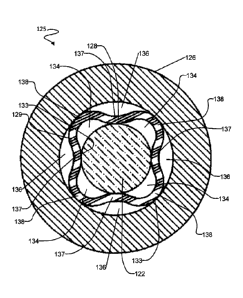
package 122 supported within a bore 127 in a section 126 of drill string.
Section 126
may, for example, comprise a drill collar, a gap sub or the like. Electronics
package
122 is smaller in diameter than bore 127. Electronics package is centralized
within
bore 127 by a tubular centralizer 128. Figures 4B and 4C show the downhole
assembly 125 without the electronics package 122.
[0085] Centralizer 128 comprises a tubular body 129 having a bore 130 for
receiving
electronics package 122 and formed to provide axially-extending inner support
surfaces 132 for supporting electronics package 122 and outer support surfaces
133
.. for bearing against the wall of bore 127 of section 126. As shown in Figure
4A,
centralizer 128 divides the annular space surrounding electronics package 122
into a
number of axial channels. The axial channels include inner channels 134
defined
between centralizer 128 and electronics package 122 and outer channels 136
defined
between centralizer 128 and the wall of section 126.
.. [0086] Centralizer 128 may be provided in one or more sections and may
extend
substantially continuously for any desired length along electronics package
122. In
some embodiments, centralizer 128 extends substantially the full length of
electronics
package 122. In some embodiments, centralizer 128 extends to support
electronics
package 122 substantially continuously along at least 60% or 70% or 80% of an
unsupported portion of electronics package 122 (e.g. a portion of electronics
package
122 extending from a point at which electronics package 122 is coupled to
section 126
to an end of electronics package 122). In some embodiments centralizer 128
engages
substantially all of the unsupported portion of electronics package 122. Here,
'substantially all' means at least 95%.
100871 In the illustrated embodiment, inner support surfaces 132 are provided
by the
ends of inwardly-directed longitudinally-extending lobes 137 and outer support
surfaces 133 are provided by the ends of outwardly-directed longitudinally-
extending
lobes 138. The number of lobes may be varied. The illustrated embodiment has
four
lobes 137 and four lobes 138. However, other embodiments may have more or
fewer
lobes. For example, some alternative embodiments have 3 to 8 lobes 138.
- 22 -
CA 2893467 2020-03-10
PCT/CA2012/050885
CA 02893467 2015-06-01
30 September 2014 30-09-2014
[0088] It is convenient but not mandatory to make the lobes of centralizer 128
symmetrical to one another. It is also convenient but not mandatory to make
the cross-
section of centralizer 128 mirror symmetrical about an axis passing through
one of the
lobes. It is convenient but not mandatory for lobes 137 and 138 to extend
parallel to
the longitudinal axis of centralizer 128. In the alternative, centralizer 128
may be
formed so that lobes 137 and 138 are helical in form.
[0089] Centralizer 128 may be made from a range of materials from metals to
plastics suitable for exposure to downhole conditions. Some non-limiting
examples
are suitable thermoplastics, elastomeric polymers, rubber, copper or copper
alloy,
alloy steel, and aluminum. For example centralizer 128 may be made from a
suitable
grade of PEEK (Polyetheretherketone) or PET (Polyethylene terephthalate)
plastic.
Where centralizer 128 is made of plastic the plastic may be fiber-filled (e.g.
with glass
fibers) for enhanced erosion resistance, structural stability and strength.
[0090] The material of centralizer 128 should be capable of withstanding
downhole
conditions without degradation. The ideal material can withstand temperature
of up to
at least 150C (preferably 175C or 200C or more), is chemically resistant or
inert to
any drilling fluid to which it will be exposed, does not absorb fluid to any
significant
degree and resists erosion by drilling fluid. In cases where centralizer 128
contacts
metal of electronics package 122 and/or bore 127 (e.g. where one or both of
electronics package 122 and bore 127 is uncoated) the material of centralizer
128 is
preferably not harder than the metal of electronics package 122 and/or section
126
that it contacts. Centralizer 128 should be stiff against deformations so that
electronics
package 122 is kept concentric within bore 127. The material characteristics
of
centralizer 128 may be uniform.
[0091] The material of centralizer 128 may also be selected for compatibility
with
sensors associated with electronics package 122. For example, where
electronics
package 122 includes a magnetometer, it is desirable that centralizer 128 be
made of a
non-magnetic material such as copper, beryllium copper, or a suitable
thermoplastic.
[0092] In cases where centralizer 128 is made of a relatively unyielding
material, a
layer of a vibration damping material such as rubber, an elastomer, a
thermoplastic or
- 23 -
AMENDED SHEET
the like may be provided between electronics package 122 and centralizer 128
and/or
between centralizer 128 and bore 127. The vibration damping material may
assist in
preventing 'pinging' (high frequency vibrations of electronics package 122
resulting
from shocks).
.. [0093] Centralizer 128 may be formed by extrusion, injection molding,
casting,
machining, or any other suitable process. Advantageously the wall thickness of
centralizer 128 can be substantially constant. This facilitates manufacture by
extrusion. In the illustrated embodiment the lack of sharp corners reduces the
likelihood of stress cracking, especially when centralizer 128 has a constant
or only
slowly changing wall thickness. In an example embodiment, the wall of
centralizer
128 has a thickness in the range of 0.1 to 0.3 inches (2 to 8 mm). In a more
specific
example embodiment, the wall of centralizer 128 is made of a thermoplastic
material
(e.g. PET or PEEK) and has a thickness of about 0.2 inches (about 5 mm).
[0094] Centralizer 128 is preferably sized to snuggly grip electronics package
122.
Preferably insertion of electronics package 122 into centralizer 128
resiliently
deforms the material of centralizer 128 such that centralizer 128 grips the
outside of
electronics package 122 firmly. Electronics package 122 may be somewhat larger
in
diameter than the space between the innermost parts of centralizer 128 to
provide an
interference fit between the electronics package and centralizer 128. The size
of the
.. interference fit is an engineering detail but may be 1/2 mm or so (a few
hundredths of
an inch).
[0095] In some applications it is advantageous for the material of centralizer
128 to
be electrically insulating. For example, where electronics package 122
comprises an
EM telemetry system, providing an electrically-insulating centralizer 128 can
prevent
the possibility of short circuits between section 126 and the outside of
electronics
package 122 as well as increase the impedance of current paths through
drilling fluid
between electronics package 122 and section 126.
[0096] Electronics package 122 may be locked against axial movement within
bore
127 in any suitable manner. For example, by way of pins, bolts, clamps, or
other
suitable fasteners. In the embodiment illustrated in Figure 4, a spider 140
having a rim
- 24 -
CA 2893467 2019-05-29
PCT/CA2012/050885
CA 02893467 2015-06-01
30 September 2014 30-09-2014
140A supported by arms 140B is attached to electronics package 122. Rim 140A
engages a ledge 141 formed at the end of a counterbore within bore 127. Rim
140A is
clamped tightly against ledge 141 by a nut 144 (see Figures 5 and 5A) that
engages
internal threads on surface 142.
[0097] In some embodiments, centralizer 128 extends from spider 140 or other
longitudinal support system for electronics package 122 continuously to the
opposing
end of electronics package 122. In other embodiments one or more sections of
centralizer 128 extend to grip electronics package 122 over at least 70% or at
least
80% or at least 90% or at least 95% of a distance from the longitudinal
support to the
opposing end of electronics package 122.
[0098] In some embodiments electronics package 122 has a fixed rotational
orientation relative to section 126. For example, in some embodiments spider
140 is
keyed, splined, has a shaped bore that engages a shaped shaft on the
electronics
package 122 or is otherwise non-rotationally mounted to electronics package
122.
Spider 140 may also be non-rotationally mounted to section 126, for example by
way
of a key, splines, shaping of the face or edge of rim 140A that engages
corresponding
shaping within bore 127 or the like.
[0099] In some embodiments electronics package 122 has two or more spiders,
electrodes, or other elements that directly engage section 126. For example,
electronics package 122 may include an EM telemetry system that has two spaced
apart electrical contacts that engage section 126. In such embodiments,
centralizer
128 may extend for a substantial portion of (e.g. at least 50% or at least 65%
or at
least 75% or at least 80% or substantially the full length of) electronics
package 122
between two elements that engage section 126.
[0100] In an example embodiment shown in Figure 5, electronics package 122 is
supported between two spiders 140 and 143. Each spider 140 and 143 engages a
corresponding landing ledge within bore 127. Each spider 140 and 143 may be
non-
rotationally coupled to both electronics package 122 and bore 127. Centralizer
128
may be provided between spiders 140 and 143. Optionally spiders 140 and 143
are
each spaced longitudinally apart from the ends of centralizer 128 by a short
distance
- 25 -
AMENDED SHEET
(e.g. up to about 1/2 meter (18 inches) or so) to encourage laminar flow of
drilling fluid
past electronics package 122.
[0101] It can be seen from Figure 4A that, in cross section, the wall 129 of
centralizer
128 extends around electronics package 122. Wall 129 is shaped to provide
outwardly
projecting lobes 138 that are outwardly convex and inwardly concave as well as
inwardly-projecting lobes 137 that are inwardly convex and outwardly concave.
In the
illustrated embodiment, each outwardly projecting lobe 138 is between two
neighbouring inwardly projecting lobes 137 and each inwardly projecting lobe
137 is
between two neighbouring outwardly projecting lobes 138. The wall of
centralizer
128 is sinuous and may be constant in thickness to form both inwardly
projecting
lobes 137 and outwardly projecting lobes 138.
[0102] In the illustrated embodiment, portions of the wall 129 of centralizer
128 bear
against the outside of the electronics package 122 and other portions of the
wall 129
of centralizer 128 bear against the inner wall of the bore 127 of section 126.
As one
travels around the circumference of centralizer 128, centralizer 128 makes
alternate
contact with electronics package 122 on the internal aspect of wall 129 of
centralizer
128 and with section 126 on the external aspect of centralizer 128. Wall 129
of
centralizer 128 zig zags back and forth between electronics package 122 and
the wall
of bore 127 of section 126. In the illustrated embodiment the parts of the
wall 129 of
centralizer 128 that extend between an area of the wall that contacts
electronics
package 122 and a part of wall 129 that contacts section 126 are curved. These
curved
wall parts are preloaded such that centralizer 128 exerts a compressive force
on
electronics package 122 and holds electronics package 122 centralized in bore
127.
[0103] When section 126 experiences a lateral shock, centralizer 128 cushions
the
effect of the shock on electronics package 122 and also prevents electronics
package
122 from moving too much away from the center of bore 127. After the shock has
passed, centralizer 128 urges the electronics package 122 back to a central
location
within bore 127. The parts of the wall 129 of centralizer 128 that extend
between an
area of the wall that contacts electronics package 122 and an area of the wall
that
contacts section 126 can dissipate energy from shocks and vibrations into the
drilling
fluid that surrounds them. Furthermore, these wall sections are pre-loaded and
exert
- 26 -
CA 2893467 2019-05-29
PCT/CA2012/050885
CA 02893467 2015-06-01
30 September 2014 30-09-2014
restorative forces that act to return electronics package 122 to its
centralized location
after it has been displaced.
101041 As shown in Figure 4A, centralizer 128 divides the annular space within
bore
127 surrounding electronics package 122 into a first plurality of inner
channels 134
inside the wall 129 of centralizer 128 and a second plurality of outer
channels 136
outside the wall 129 of centralizer 128. Each of inner channels 134 lies
between two
of outer channels 136 and is separated from the outer channels 136 by a part
of the
wall of centralizer 128. One advantage of this configuration is that the
curved, pre-
tensioned flexed parts of the wall tend to exert a restoring force that urges
electronics
package 122 back to its equilibrium (centralized) position if, for any reason,
electronics package 122 is moved out of its equilibrium position. The presence
of
drilling fluid in channels 134 and 136 tends to damp motions of electronics
package
122 since transverse motion of electronics package 122 results in motions of
portions
of the wall of centralizer 128 and these motions transfer energy into the
fluid in
channels 134 and 136. In addition, dynamics of the flow of fluid through
channels 134
and 136 may assist in stabilizing centralizer 128 by carrying off energy
dissipated into
the fluid by centralizer 128.
[0105] The preloaded parts of wall 129 provide good mechanical coupling of the
electronics package 122 to the drill string section 126 in which the
electronics
package 122 is supported. Centralizer 128 may provide such coupling along the
length of the electronics package 122. This good coupling to the drill string
section
126, which is typically very rigid, can increase the resonant frequencies of
the
electronics package 122, thereby making the electronics package 122 more
resistant to
being damaged by high amplitude low frequency vibrations that typically
accompany
drilling operations.
[01061 Figures 6 and 6A show an example centralizer 160 formed with a wall 162
configured to provide longitudinal ridges 164 that twist around the
longitudinal
centerline of centralizer 160 to form helixes. In the illustrated embodiment,
centralizer
160 has a cross-sectional shape in which wall 162 forms two outwardly
projecting
lobes 166, which are each outwardly convex and inwardly concave and two
inwardly
projecting lobes 168. Centralizers configured to have other numbers of lobes
may also
- 27 -
AMENDED SHEET
be made to have a helical twist. For example, centralizers that, in cross
section,
provide 3 to 8 lobes may be constructed so that the lobes extend along helical
paths.
101071 Inwardly-projecting lobes 168 are configured to grip an electronics
package by
spiralling around the outer surface of the electronics package. The tubular
body of
centralizer 160 is subject to a twist so that the lobes become displaced in a
rotated or
angular fashion as one traverses along the length of centralizer 160. At each
point
along the electronics package 122 the electronics package 122 is held between
two
opposing lobes 168. The orientation of lobes 168 is different for different
positions
along the electronics package so that the electronics package is held against
radial
movement within the bore of centralizer 160. Each ridge 164 makes at least a
half
twist over the length of centralizer 160. In some embodiments, each ridge 164
makes
at least one full twist around the longitudinal axis of centralizer 160 over
the length of
centralizer 160.
[0108] A centralizer as described herein may be anchored against longitudinal
movement and/or rotational movement within bore 127 if desired. For example
the
centralizer may be keyed onto a landing shoulder in bore 127 and held axially
in place
by a threaded feature that locks it down. For example, the centralizer may be
gripped
between the end of one drill collar and a landing shoulder. Figure 5B
illustrates an
example embodiment wherein a centralizer 128 engages features of a ring 150
that is
held against a landing 141 within bore 127 of section 126. In the illustrated
embodiment, notches 154 on an end of centralizer 128 engage corresponding
teeth
152 on ring 150. Ring 150 may be held in place against landing 141 by means of
a
suitable nut, the end of an adjoining drill string section, a spider or other
part of a
probe or the like. In some embodiments, ring 150 is attached to or is part of
a spider
that supports a downhole probe in bore 127.
[0108A] In Figures 4, 4B, 5 and 6 arrow Al shows a downhole direction and
arrow
A2 shows an uphole direction.
[0109] A centralizer as described herein may optionally interface non-
rotationally to
an electronics package 122 (for example, the electronics package 122 may have
features that project to engage between inwardly-projecting lobes of a
centralizer) so
- 28 -
CA 2893467 2020-03-10
that the centralizer provides enhanced damping of torsional vibrations of the
electronics package 122.
- 28a -
CA 2893467 2019-05-29
PCT/CA2012/050885
CA 02893467 2015-06-01
30 September 2014 30-09-2014
[0110] One method of use of a centralizer as described herein is to insert the
centralizer into a section of a drill string such as a gap sub, drill collar
or the like. The
section has a bore having a diameter Dl. The centralizer, in an uninstalled
configuration free of external stresses prior to installation, has outermost
points lying
on a circle of diameter D2 with D2>D1. The method involves inserting the
centralizer
into the section. In doing so, the outermost points of the centralizer bear
against the
wall of the bore of the section and are therefore compressed inwardly. The
configuration of centralizer 128 allows this to occur so that centralizer 128
may be
easily inserted into the section. Insertion of centralizer 128 into the
section moves the
innermost points of centralizer 128 inwardly.
[0111] In some embodiments, centralizer 128 is inserted into the section until
the end
being inserted into the section abuts a landing step in the bore of the
section. The
centralizer may then be constrained against longitudinal motion by providing a
member that bears against the other end of the centralizer. For example, the
section
may comprise a number of parts (e.g. a number of collars) that can be coupled
together. The centralizer may be held between the end of one collar or other
part of
the section and a landing step.
[0112] After installation of the centralizer into the section, the innermost
points on the
centralizer lie on a central circle having a diameter D3. An electronics
package or
other elongated object to be centralized having a diameter D4 with D4>D3 may
then
be introduced longitudinally into centralizer. This forces the innermost
portions of
centralizer outwardly and preloads the sections of the wall of centralizer
that extend
between the innermost points and the outermost points of centralizer. After
the
electronics package has been inserted, the electronics package may be anchored
against longitudinal motion.
[0113] In some applications, as drilling progresses, the outer diameter of
components
of the drill string may change. For example, a well bore may be stepped such
that the
wellbore is larger in diameter near the surface than it is in its deeper
portions. At
different stages of drilling a single hole, it may be desirable to install the
same
electronics package in drill string sections having different dimensions.
Centralizers
as described herein may be made in different sizes to support an electronics
package
- 29 -
AMENDED SHEET
PCT/CA2012/050885
CA 02893467 2015-06-01
30 September 2014 30-09-2014
within bores of different sizes. Centralizers as described herein may be
provided at a
well site in a set comprising centralizers of a plurality of different sizes.
The
centralizers may be provided already inserted into drill string sections or
not yet
inserted into drill string sections.
[0114] Moving a downhole probe or other electronics package into a drill
string
section of a different size may be easily performed at a well site by removing
the
electronics package from one drill string section, changing a spider or other
longitudinal holding device to a size appropriate for the new drill string
section and
inserting the electronics package into the centralizer in the new drill string
section.
[0115] For example, a set comprising: spiders or other longitudinal holding
devices of
different sizes and centralizers of different sizes may be provided. The set
may, by
way of non-limiting example, comprise spiders and centralizers dimensioned for
use
with drill collars having bores of a plurality of different sizes. For
example, the
spiders and centralizers may be dimensioned to support a given probe in the
bores of
drill collars of any of a number of different standard sizes. The set of
centralizers
may, for example include centralizers sufficient to support a given probe in
any of a
defined plurality of differently-sized drill collars. For example, the set may
comprise a
selection of centralizers that facilitate supporting the probe in drill
collars having
outside diameters such as two or more of: 4 1/4 inches (12 cm), 6 'A inches
(17 cm), 8
.. inches (20 cm), 9 V2 inches (24 cm) and 11 inches (28 cm). The drill
collars may have
industry-standard sizes. The drill collars may collectively include drill
collars of two,
three or more different bore diameters. The centralizers may, by way of non-
limiting
example, be dimensioned in length to support probes having lengths in the
range of 2
to 20 meters.
.. [0116] In some embodiments the set comprises, for each of a plurality of
different
sizes of drill string section, a plurality of different sections of
centralizer that may be
used together to support a downhole probe of a desired length. By way of non-
limiting example, two 3 meter long sections of centralizer may be provided for
each
of a plurality of different bore sizes. The centralizers may be used to
support 6 meters
of a downhole probe.
- 30 -
AMENDED SHEET
PCT/CA2012/050885
CA 02893467 2015-06-01
30 September 2014 30-09-2014
[0117] Embodiments as described above may provide one or more of the following
advantages. Centralizer 128 may extend for the full length of the electronics
package
122 or any desired part oC that length. Centralizer 128 positively prevents
electronics
package 122 from contacting the inside of bore 127 even under severe shock and
vibration. The cross-sectional area occupied by centralizer 128 can be
relatively
small, thereby allowing a greater area for the flow of fluid past electronics
package
122 than would be provided by some other centralizers that occupy greater
cross-
sectional areas. Centralizer 128 can dissipate energy from shocks and
vibration into
the fluid within bore 127. The geometry of centralizer 128 is self-correcting
under
certain displacements. For example, restriction of flow through one channel
tends to
cause forces directed so as to open the restricted channel. Especially where
centralizer
128 has four or more inward lobes, electronics package 122 is mechanically
coupled
to section 126 in all directions, thereby reducing the possibility for
localized bending
of the electronics package 122 under severe shock and vibration. Reducing
local
bending of electronics package 122 can facilitate longevity of mechanical and
electrical components and reduce the possibility of catastrophic failure of
the housing
of electronics assembly 122 or components internal to electronics package 122
due to
fatigue. Centralizer 128 can accommodate deviations in the sizing of
electronics
package 122 and/or the bore 127 of section 126. Centralizer 128 can
accommodate
slick electronics packages 122 and can allow an electronics package 122 to be
removable while downhole (since a centralizer 128 can be made so that it does
not
interfere with withdrawal of an electronics package 122 in a longitudinal
direction).
Centralizer 128 can counteract gravitational sag and maintain electronics
package 122
central in bore 127 during directional drilling or other applications where
bore 127 is
horizontal or otherwise non-vertical.
[0118] Apparatus as described herein may be applied in a wide range of
subsurface
drilling applications. For example, the apparatus may be applied to support
downhole
electronics that provide telemetry in logging while drilling (1,WD') and/or
measuring
while drilling (`MWIY) telemetry applications. The described apparatus is not
limited
.. to use in these contexts, however.
[0119] One example application of apparatus as described herein is directional
drilling. In directional drilling the section of a drill string containing a
downhole
- 31 -
AMENDED SHEET
PCT/CA2012/050885
CA 02893467 2015-06-01
30 September 2014 30-09-2014
probe may be non-vertical. A centralizer as described herein can maintain the
downhole probe centered in the drill string against gravitational sag, thereby
maintaining sensors in the downhole probe true to the bore of the drill
string.
[0120] A wide range of alternatives are possible. For example, it is not
mandatory
that section 126 be a single component. In some embodiments section 126
comprises
a plurality of components that are assembled together into the drill string
(e.g. a
plurality of drill collars). Centralizer 128 is not necessarily entirely
formed in one
piece. In some embodiments, additional layers are added to the wall of
centralizer 128
to enhance stiffness, resistance to abrasion or other mechanical properties.
The wall
.. thickness of centralizer 128 may be varied to adjust mechanical properties
of
centralizer 128. Apertures or holes may be formed in the wall of the
centralizer to
allow fluid flow or to provide for other components to pass through the wall
of the
centralizer.
[0121] In a preferred embodiment, centralizer 128 supports electronics package
122
continuously or substantially continuously over a longitudinally-extending
section of
electronics package 122. Centralizer 128 may, for example, comprise a tubular
structure comprising resiliently deformable features which can be introduced
into the
bore of section 126 and can then flex to accommodate the insertion of
electronics
package 122 into bore 127 between the features of centralizer 128. Centralizer
128 is
constructed to continuously exert a compressive force on the outside surface
of
electronics package 122 and to exert an outward force on the walls of bore
127,
thereby mechanically coupling electronics package 122 to section 126.
[0122] Section 126 is very stiff and therefore the resonant frequency of
electronics
package 122 is further raised by the mechanical coupling of electronics
package 122
to section 126.
[0123] In some embodiments of downhole assembly 125, electronics package 122
comprises probe 31.This mechanically coupled structure, by virtue of its
increased
stiffness, has a higher resonant frequency than any of its component parts. A
structure
with a higher resonant frequency may be less susceptible to damage from low
.. frequency vibrations which may accompany drilling operations. In some
- 32 -
AMENDED SHEET
embodiments, all fundamental vibrational modes of probe 31 have frequencies
well in
excess of 10 Hz or 15 Hz.
[0124] Furthermore, this mechanically coupled structure acts to maintain the
concentricity of electronics unit 31B of probe 31 within section 126. This can
be
advantageous in some circumstances. For example, when electronics unit 31B
comprises a directional sensor, movement of electronics unit 31B within
section 126
can introduce an offset to the measurements of the directional sensor.
[0125] Figure 7 illustrates electronics package 122 partially inserted into
centralizer
128 located within bore 127 of section 126. This Figure shows how the passage
of
electronics package 122 can force inwardly-directed parts of centralizer 128
outward
such that electronics package 122 is tightly coupled to the inner wall of
section 126 by
centralizer 128.
[0126] In some embodiments of the invention, a gaseous drilling fluid is used,
for
example, air. In some embodiments, a drilling fluid comprising a liquid and a
gas may
be used, for example 10-15% liquid and 80-85% gas. The flow rate of a gaseous
drilling fluid may range from, for example, 1,500 standard cubic feet per
minute
(SCF/min) to 13,000 SCF/min (42475 1/min to 368119 1/min). In other
embodiments,
other flow rates may be used.
[0127] A gaseous drilling fluid generally provides much less damping of
vibrations of
the probe than a liquid drilling fluid. For example, a probe being used in
conjunction
with a gaseous drilling fluid may experience g forces due to shocks haying
magnitudes several times higher than would be the case if the probe were
surrounded
by a liquid drilling fluid.
[0128] Since centralizer 128 may cooperate with drilling fluid within bore 127
to
damp undesired motions of electronics package 122, centralizer 128 may be
designed
with reference to the type of fluid that will be used in drilling. For a
gaseous drilling
fluid, centralizer 128 may be made with thicker walls and/or made of a stiffer
material
so that it can hold electronics package 122 against motions in the absence of
an
incompressible liquid drilling fluid. Conversely, the presence of liquid
drilling fluid in
- 33 -
CA 2893467 2019-05-29
PCT/CA2012/050885
CA 02893467 2015-06-01
30 September 2014 30-09-2014
channels 134 and 136 tends to dampen high-frequency vibrations and to cushion
transverse motions of electronics package 122. Consequently, a centralizer 128
for
use with liquid drilling fluids may have thinner walls than a centralizer 128
designed
for use with gaseous drilling fluids.
[0129] When a gaseous drilling fluid is used the benefits of the methods and
apparatus disclosed herein may be especially significant because without the
dampening effects of a liquid drilling fluid, probes are even more susceptible
to
damage vibrations.
Interpretation of Terms
[0130] Unless the context clearly requires otherwise, throughout the
description and
the claims:
= "comprise," "comprising," and the like are to be construed in an
inclusive
sense, as opposed to an exclusive or exhaustive sense; that is to say, in the
sense of
"including, but not limited to".
= "connected," "coupled," or any variant thereof, means any connection or
coupling, either direct or indirect, between two or more elements; the
coupling or
connection between the elements can be physical, logical, or a combination
thereof.
= "herein," "above," "below," and words of similar import, when used to
describe this specification shall refer to this specification as a whole and
not to any
particular portions of this specification.
= "or," in reference to a list of two or more items, covers all of the
following
interpretations of the word: any of the items in the list, all of the items in
the list, and
any combination of the items in the list.
= the singular forms "a", "an" and "the" also include the meaning of any
appropriate plural forms.
[0131] Words that indicate directions such as "vertical", "transverse",
"horizontal",
"upward", "downward", "forward", "backward", "inward", "outward", "left",
"right",
- 34 -
AMENDED SHEET
"front", "back" , "top", "bottom", "below", "above", "under", and the like,
used in
this description and any accompanying claims (where present) depend on the
specific
orientation of the apparatus described and illustrated. The subject matter
described
herein may assume various alternative orientations. Accordingly, these
directional
terms are not strictly defined and should not be interpreted narrowly.
[0132] Where a component (e.g. a circuit, module, assembly, device, drill
string
component, drill rig system, etc.) is referred to above, unless otherwise
indicated,
reference to that component (including a reference to a "means") should be
interpreted
as including as equivalents of that component any component which performs the
.. function of the described component (i.e., that is functionally
equivalent), including
components which are not structurally equivalent to the disclosed structure
which
performs the function in the illustrated exemplary embodiments of the
invention.
[0133] Specific examples of systems, methods and apparatus have been described
herein for purposes of illustration. These are only examples. The technology
provided
herein can be applied to systems other than the example systems described
above.
Many alterations, modifications, additions, omissions and permutations are
possible
within the practice of this invention. This invention includes variations on
described
embodiments that would be apparent to the skilled addressee, including
variations
obtained by: replacing features, elements and/or acts with equivalent
features,
elements and/or acts; mixing and matching of features, elements and/or acts
from
different embodiments; combining features, elements and/or acts from
embodiments
as described herein with features, elements and/or acts of other technology;
and/or
omitting combining features, elements and/or acts from described embodiments.
[0134] It is therefore intended that the following appended claims and claims
hereafter introduced are interpreted to include all such modifications,
permutations,
additions, omissions and sub-combinations as may reasonably be inferred. The
scope
of the claims should not be limited by the preferred embodiments set forth in
the
examples, but should be given the broadest interpretation consistent with the
description as a whole.
- 35 -
CA 2893467 2020-03-10