Note: Descriptions are shown in the official language in which they were submitted.
-1-
MANUAL RELEASE SYSTEMS FOR AMBULANCE COTS
CROSS-REFERENCE TO RELATED APPLICATIONS
[0001] This application claims priority to U.S. provisional application
61/733,060 filed
December 4, 2012.
TECHNICAL FIELD
[0002] The present disclosure is generally related to manual release
components, and is
specifically directed to manual release components for hydraulically powered
ambulance cots.
BACKGROUND
[0003] There are a variety of emergency cots in use today. Such emergency
cots may be
designed to transport and load bariatric patients into an ambulance.
[0004] For example, the PROFlex X cot, by Femo-Washington, Inc. of
Wilmington, Ohio
U.S.A., is a manually actuated cot that may provide stability and support for
loads of about 700
pounds (about 317.5 kg). The PROFlexXO cot includes a patient support portion
that is attached
to a wheeled undercarriage. The wheeled under carriage includes an X-frame
geometry that can
be transitioned between nine selectable positions. One recognized advantage of
such a cot design
is that the X-frame provides minimal flex and a low center of gravity at all
of the selectable
positions. Another recognized advantage of such a cot design is that the
selectable positions may
provide better leverage for manually lifting and loading bariatric patients.
[0005] Another example of a cot designed for bariatric patients, is the
POWERFlexx+
Powered Cot, by Femo-Washington, Inc. The POWERFlexx+ Powered Cot includes a
battery
CA 2893493 2018-10-31
-2-
powered actuator that may provide sufficient power to lift loads of about 700
pounds (about
317.5 kg). One recognized advantage of such a cot design is that the cot may
lift a bariatric
patient up from a low position to a higher position, i.e., an operator may
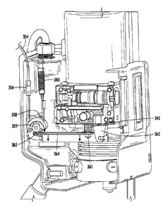
have reduced situations
that require lifting the patient.
f00061 A further variety is a multipurpose roll-in emergency cot having a
patient support
stretcher that is removably attached to a wheeled undercarriage or
transporter. The patient
support stretcher when removed for separate use from the transporter may be
shuttled around
horizontally upon an included set of wheels. One recognized advantage of such
a cot design is
that the stretcher may be separately rolled into an emergency vehicle such as
station wagons,
vans, modular ambulances, aircrafts, or helicopters, where space and reducing
weight is a
premium.
[0007] Another advantage of such a cot design is that the separated
stretcher may be more
easily carried over uneven terrain and out of locations where it is
impractical to use a complete
cot to transfer a patient. Example of such cots can be found in U. S. Patent
Nos. 4,037,871,
4,921,295, and International Publication No. W02001070161.
[0008] Although the foregoing multipurpose roll-in emergency cots have been
generally
adequate for their intended purposes, they have not been satisfactory in all
aspects. For example,
the foregoing emergency cots are loaded into ambulances according to loading
processes that
require at least one operator to support the load of the cot for a portion of
the respective loading
process.
CA 2893493 2018-10-31
CA 02893493 2015-06-02
WO 2014/089180 PCT/US2013/073069
-3-
SUMMARY
[0009] According to one embodiment, a cot is provided, wherein the cot
comprises a support
frame, legs coupled to the support frame, at least one hydraulic actuator
configured to raise or
lower the legs, and a manual release system coupled to the at least one
actuator and configured to
lower the cot manually at a controlled descent rate. The manual release system
comprises a
manual actuation component, a manual release valve operable to be opened upon
actuation by the
manual actuation component, a fluid reservoir operable to receive hydraulic
fluid from the at
least one actuator upon opening of the manual release valve, and a flow
regulator configured to
control a flow rate of the hydraulic fluid into the fluid reservoir, wherein
the release of hydraulic
fluid into the fluid reservoir at the controlled flow rate is configured to
manually lower the cot at
a controlled descent rate.
[0010] These and additional features provided by the embodiments of the
present disclosure
will be more fully understood in view of the following detailed description,
in conjunction with
the drawings.
BRIEF DESCRIPTION OF THE DRAWINGS
[0011] The following detailed description of specific embodiments of the
present disclosures
can be best understood when read in conjunction with the following drawings,
where like
structure is indicated with like reference numerals and in which:
[0012] FIG. 1 is a perspective view depicting a cot according to one or
more embodiments
described herein;
CA 02893493 2015-06-02
WO 2014/089180 PCT/US2013/073069
-4-
[0013] FIG. 2 is a top view depicting a cot according to one or more
embodiments described
herein;
[0014] FIGS. 3A-3C is a side view depicting a raising and/or lower sequence
of a cot
according to one or more embodiments described herein;
[0015] FIGS. 4A-4E is a side view depicting a loading and/or unloading
sequence of a cot
according to one or more embodiments described herein;
[0016] FIG. 5 schematically depicts an actuator system of a cot according
to one or more
embodiments described herein;
[0017] FIG. 6 schematically depicts a master-salve hydraulic circuit
according to one or more
embodiments described herein;
[0018] FIGS. 7A and 7B schematically depict a master-salve hydraulic
circuit according to
one or more embodiments described herein;
[0019] FIGS. 8 depicts the position of a manual release component according
to one or more
embodiments described herein;
[0020] FIGS. 9 depicts the manual release component according to one or
more embodiments
described herein;
[0021] FIGS. 10 depicts in phantom the manual release according to one or
more
embodiments described herein; and
[0022] FIG. 11 depicts the components of a manual release on the underside
of an actuator
according to one or more embodiments described herein.
CA 02893493 2015-06-02
WO 2014/089180 PCT/US2013/073069
-5-
[0023] The embodiments set forth in the drawings are illustrative in nature
and not intended
to be limiting of the embodiments described herein. Moreover, individual
features of the
drawings and embodiments will be more fully apparent and understood in view of
the detailed
description.
DETAILED DESCRIPTION
[0024] Referring to FIG. 1, a roll-in cot 10 for transport and loading is
shown. The roll-in cot
comprises a support frame 12 comprising a front end 17, and a back end 19. As
used herein,
the front end 17 is synonymous with the loading end, i.e., the end of the roll-
in cot 10 which is
loaded first onto a loading surface. Conversely, as used herein, the back end
19 is the end of the
roll-in cot 10 which is loaded last onto a loading surface. Additionally it is
noted, that when the
roll-in cot 10 is loaded with a patient, the head of the patient may be
oriented nearest to the front
end 17 and the feet of the patient may be oriented nearest to the back end 19.
Thus, the phrase
"head end" may be used interchangeably with the phrase "front end," and the
phrase "foot end"
may be used interchangeably with the phrase "back end." Furthermore, it is
noted that the phrases
"front end" and "back end" are interchangeable. Thus, while the phrases are
used consistently
throughout for clarity, the embodiments described herein may be reversed
without departing
from the scope of the present disclosure. Generally, as used herein, the term
"patient" refers to
any living thing or formerly living thing such as, for example, a human, an
animal, a corpse and
the like.
[0025] Referring to FIG. 2, the front end 17 and/or the back end 19 may be
telescoping. In
one embodiment, the front end 17 may be extended and/or retracted (generally
indicated in FIG.
2 by arrow 217). In another embodiment, the back end 19 may be extended and/or
retracted
CA 02893493 2015-06-02
WO 2014/089180 PCT/US2013/073069
-6-
(generally indicated in FIG. 2 by arrow 219). Thus, the total length between
the front end 17 and
the back end 19 may be increased and/or decreased to accommodate various sized
patients.
[0026] Referring collectively to FIGS. 1 and 2, the support frame 12 may
comprise a pair of
substantially parallel lateral side members 15 extending between the front end
17 and the back
end 19. Various structures for the lateral side members 15 are contemplated.
In one embodiment,
the lateral side members 15 may be a pair of spaced metal tracks. In another
embodiment, the
lateral side members 15 comprise an undercut portion 115 that is engageable
with an accessory
clamp (not depicted). Such accessory clamps may be utilized to removably
couple patient care
accessories such as a pole for an IV drip to the undercut portion 115. The
undercut portion 115
may by provided along the entire length of the lateral side members to allow
accessories to be
removably clamped to many different locations on the roll-in cot 10.
[0027] Referring again to FIG. 1, the roll-in cot 10 also comprises a pair
of retractable and
extendible front legs 20 coupled to the support frame 12, and a pair of
retractable and extendible
back legs 40 coupled to the support frame 12. The roll-in cot 10 may comprise
any rigid material
such as, for example, metal structures or composite structures. Specifically,
the support frame 12,
the front legs 20, the back legs 40, or combinations thereof may comprise a
carbon fiber and
resin structure. As is described in greater detail herein, the roll-in cot 10
may be raised to
multiple heights by extending the front legs 20 and/or the back legs 40, or
the roll-in cot 10 may
be lowered to multiple heights by retracting the front legs 20 and/or the back
legs 40. It is noted
that terms such as "raise," "lower," "above," "below," and "height" are used
herein to indicate the
distance relationship between objects measured along a line parallel to
gravity using a reference
(e.g. a surface supporting the cot).
CA 02893493 2015-06-02
WO 2014/089180 PCT/US2013/073069
-7-
[0028] In specific embodiments, the front legs 20 and the back legs 40 may
each be coupled
to the lateral side members 15. As shown in FIGS. 3A-4E, the front legs 20 and
the back legs 40
may cross each other, when viewing the cot from a side, specifically at
respective locations
where the front legs 20 and the back legs 40 are coupled to the support frame
12 (e.g., the lateral
side members 15 (FIGS. 1-2)). As shown in the embodiment of FIG. 1, the back
legs 40 may be
disposed inwardly of the front legs 20, i.e., the front legs 20 may be spaced
further apart from
one another than the back legs 40 are spaced from one another such that the
back legs 40 are each
located between the front legs 20. Additionally, the front legs 20 and the
back legs 40 may
comprise front wheels 26 and back wheels 46 which enable the roll-in cot 10 to
roll.
[0029] In one embodiment, the front wheels 26 and back wheels 46 may be
swivel caster
wheels or swivel locked wheels. As the roll-in cot 10 is raised and/or
lowered, the front wheels
26 and back wheels 46 may be synchronized to ensure that the plane of the
lateral side members
15 of the roll-in cot 10 and the plane of the wheels 26, 46 are substantially
parallel.
[0030] Referring again to FIG. 1, the roll-in cot 10 may also comprise a
cot actuation system
comprising a front actuator 16 configured to move the front legs 20 and a back
actuator 18
configured to move the back legs 40. The cot actuation system may comprise one
unit (e.g., a
centralized motor and pump) configured to control both the front actuator 16
and the back
actuator 18. For example, the cot actuation system may comprise one housing
with one motor
capable to drive the front actuator 16, the back actuator 18, or both
utilizing valves, control logic
and the like. Alternatively, as depicted in FIG. 1, the cot actuation system
may comprise separate
units configured to control the front actuator 16 and the back actuator 18
individually. In this
embodiment, the front actuator 16 and the back actuator 18 may each include
separate housings
with individual motors to drive each of the front actuator 16 and the back
actuator 18.
CA 02893493 2015-06-02
WO 2014/089180 PCT/US2013/073069
-8-
[0031] Referring to FIG. 1, the front actuator 16 is coupled to the support
frame 12 and
configured to actuate the front legs 20 and raise and/or lower the front end
17 of the roll-in cot
10. Additionally, the back actuator 18 is coupled to the support frame 12 and
configured to
actuate the back legs 40 and raise and/or lower the back end 19 of the roll-in
cot 10. The roll-in
cot 10 may be powered by any suitable power source. For example, the roll-in
cot 10 may
comprise a battery capable of supplying a voltage of, such as, about 24 V
nominal or about 32 V
nominal for its power source.
[0032] The front actuator 16 and the back actuator 18 are operable to
actuate the front legs 20
and back legs 40, simultaneously or independently. As shown in FIGS. 3A-4E,
simultaneous
and/or independent actuation allows the roll-in cot 10 to be set to various
heights. The actuators
described herein may be capable of providing a dynamic force of about 350
pounds (about 158.8
kg) and a static force of about 500 pounds (about 226.8 kg). Furthermore, the
front actuator 16
and the back actuator 18 may be operated by a centralized motor system or
multiple independent
motor systems.
[0033] In one embodiment, schematically depicted in FIGS. 1-2 and 5, the
front actuator 16
and the back actuator 18 comprise hydraulic actuators for actuating the roll-
in cot 10. In the
embodiment depicted in FIG. 6, the front actuator 16 and the back actuator 18
are dual piggy
back hydraulic actuators, i.e., the front actuator 16 and the back actuator 18
each forms a master-
slave hydraulic circuit 300. The master-slave hydraulic circuit 300 comprises
four hydraulic
cylinders with four extending rods that are piggy backed (i.e., mechanically
coupled) to one
another in pairs. Thus, the dual piggy back actuator comprises a first
hydraulic cylinder with a
first rod, a second hydraulic cylinder with a second rod, a third hydraulic
cylinder with a third
rod and a fourth hydraulic cylinder with a fourth rod. It is noted that, while
the embodiments
CA 02893493 2015-06-02
WO 2014/089180 PCT/US2013/073069
-9-
described herein make frequent reference to a master-slave system comprising
four hydraulic
cylinders, the master-salve hydraulic circuits described herein can include
any even number of
hydraulic cylinders.
[0034]
Referring collectively to FIG. 5, the front actuator 16 and the back actuator
18
comprises a rigid support frame 180 that is substantially "H" shaped (i.e.,
two vertical portions
connected by a cross portion). The rigid support frame 180 comprises a cross
member 182 that is
coupled to two vertical members 184 at about the middle of each of the two
vertical members
184. A pump motor 160 and a fluid reservoir 162 are coupled to the cross
member 182 and in
fluid communication. In one embodiment, the pump motor 160 and the fluid
reservoir 162 are
disposed on opposite sides of the cross member 182 (e.g., the fluid reservoir
162 disposed above
the pump motor 160). Specifically, the pump motor 160 may be a brushed bi-
rotational electric
motor with a peak output of about 1400 watts. The rigid support frame 180 may
include
additional cross members or a backing plate to provide further rigidity and
resist twisting or
lateral motion of the vertical members 184 with respect to the cross member
182 during
actuation.
[0035] Each
vertical member 184 comprises a pair of piggy backed hydraulic cylinders
(i.e.,
a first hydraulic cylinder and a second hydraulic cylinder or a third
hydraulic cylinder and a
fourth hydraulic cylinder) wherein the first cylinder extends a rod in a first
direction and the
second cylinder extends a rod in a substantially opposite direction. When the
cylinders are
arranged in one master-slave configuration, one of the vertical ..... members
184 comprises an upper
master cylinder 168 and a lower master cylinder 268. The other of the vertical
members 184
comprises an upper slave cylinder 169 and a lower slave cylinder 269. It is
noted that, while
master cylinders 168, 268 are piggy backed together and extend rods 165, 265
in substantially
CA 02893493 2015-06-02
WO 2014/089180 PCT/US2013/073069
-10-
opposite directions, master cylinders 168,268 may be located in alternate
vertical members 184
and/or extend rods 165, 265 in substantially the same direction.
[0036] Referring now to FIG. 6, the master-slave hydraulic circuit 300 can
be formed by
placing multiple cylinders in fluidic communication with each other. In one
embodiment, an
upper master cylinder 168 is in fluidic communication with an upper slave
cylinder 169 and may
communicate hydraulic fluid via a fluid connection 170. A lower master
cylinder 268 is in
fluidic communication with a lower slave cylinder 269 and may communicate
hydraulic fluid via
a fluid connection 270.
[0037] The upper master cylinder 168 is in fluidic communication with a
fluid connection
312, which is in fluidic communication with a fluid connection 310. Similarly,
the lower master
cylinder 268 is in fluidic communication with a fluid connection 312, which is
in fluidic
communication with the fluid connection 310. When the upper master rod 165,
the lower master
rod 265, the upper slave rod 167 and the lower slave rod 267 are extended,
hydraulic fluid can be
supplied from the pump motor 160 via the fluid connection 310. Specifically,
the pump motor
160 can be in fluidic communication with a fluid connection 316. A check valve
330 can be in
fluidic communication with both the fluid connection 310 and the fluid
connection 316 such that
hydraulic fluid can be supplied from the fluid connection 316 to the fluid
connection 310, but
hydraulic fluid is prevented from being supplied to the fluid connection 316
from the fluid
connection 310. When the pump motor 160 is actuated in a first direction,
hydraulic fluid can be
delivered from the fluid reservoir 162 to the upper master cylinder 168 and
the lower master
cylinder 268.
CA 02893493 2015-06-02
WO 2014/089180 PCT/US2013/073069
-11-
[0038] The upper slave cylinder 169 is in fluidic communication with a
fluid connection 324,
which is in fluidic communication with a fluid connection 320. Similarly, the
lower slave
cylinder 269 is in fluidic communication with a fluid connection 322, which is
in fluidic
communication with the fluid connection 320. When the upper master rod 165,
the lower master
rod 265, the upper slave rod 167 and the lower slave rod 267 are extended,
hydraulic fluid can be
supplied from the fluid connection 320 to the fluid reservoir 162.
[0039] In one embodiment, a counterbalance valve 336 can be in fluidic
communication with
both the fluid connection 320 and the fluid reservoir 162. A pilot line 318
can be in fluidic
communication with both the fluid connection 316 and the counterbalance valve
336. The
counterbalance valve 336 can allow hydraulic fluid to flow from the fluid
reservoir 162 to the
fluid connection 320, and prevent hydraulic fluid from flowing from the fluid
connection 320 to
the fluid reservoir 162, unless an appropriate pressure is received via the
pilot line 318. When
the pump motor 160 pumps hydraulic fluid through fluid connection 316, the
pilot line 318 can
cause the counterbalance valve 336 to modulate and allow hydraulic fluid to
flow from the fluid
connection 320 to the fluid reservoir 162. Accordingly, when the pump motor
160 is actuated in
a first direction, hydraulic fluid can be delivered from the upper slave
cylinder 169 and the lower
slave cylinder 269 to the fluid reservoir 162.
[0040] When the upper master rod 165, the lower master rod 265, the upper
slave rod 167
and the lower slave rod 267 are retracted, hydraulic fluid can be supplied
from the pump motor
160 via the fluid connection 320. Specifically, the pump motor 160 can be in
fluidic
communication with a fluid connection 326. A check valve 332 can be in fluidic
communication
with both the fluid connection 320 and the fluid connection 326 such that
hydraulic fluid can be
CA 02893493 2015-06-02
WO 2014/089180 PCT/US2013/073069
-12-
supplied from the fluid connection 326 to the fluid connection 320, but
hydraulic fluid is
prevented from being supplied to the fluid connection 320 from the fluid
connection 326.
[0041] Accordingly, when the pump motor 160 is actuated in a second
direction, hydraulic
fluid can be delivered from the fluid reservoir 162 to the upper slave
cylinder 169 and the lower
slave cylinder 269. Also, hydraulic fluid can be delivered from the upper
master cylinder 168
and the lower master cylinder 268 to the fluid reservoir 162. Specifically, a
counterbalance valve
334 can be in fluidic communication with both the fluid connection 310 and the
fluid reservoir
162. A pilot line 328 can be in fluidic communication with both the fluid
connection 326 and the
counterbalance valve 334. The counterbalance valve 334 can allow hydraulic
fluid to flow from
the fluid reservoir 162 to the fluid connection 310, and prevent hydraulic
fluid from flowing from
the fluid connection 310 to the fluid reservoir 162, unless an appropriate
pressure is received via
the pilot line 328. When the pump motor 160 pumps hydraulic fluid through
fluid connection
326, the pilot line 328 can cause the counterbalance valve 334 to modulate and
allow hydraulic
fluid to flow from the fluid connection 310 to the fluid reservoir 162.
Accordingly, when the
pump motor 160 is actuated in the second direction, hydraulic fluid can be
delivered from the
upper master cylinder 168 and the lower master cylinder 268 to the fluid
reservoir 162.
[0042] While the cot actuation system is typically powered, the cot
actuation system may
also comprise a manual release system coupled to the at least one actuator and
configured to
lower the cot manually at a controlled descent rate. The manual release system
comprises a
manual actuation component 355 (e.g., a button, handle, knob, tension member,
switch, linkage
or lever) that actuates a manual release valve to allow an operator to lower
at least one actuator
(e.g., the front actuator 16, the back actuator 18, or both) manually.
CA 02893493 2015-06-02
WO 2014/089180 PCT/US2013/073069
-13-
[0043] Referring to FIGS. 9-11, the manual actuation component 355 actuates
a manual
release valve 342 that is normally closed to an open position. As shown in
FIG. 6, the manual
valve 342 can be in fluidic communication with the fluid reservoir 162 and a
flow regulator 344.
The flow regulator 344 can also be in fluidic communication with the fluid
connection 310.
Thus, when a load is applied to the roll-in cot 10 and the manual valve 342 is
opened, hydraulic
fluid can be delivered from the upper master cylinder 168 and the lower master
cylinder 268
through the flow regulator 344 to the fluid reservoir 162. Accordingly, the
flow regulator 344,
which may be triggered by the application of a load force, can be utilized to
provide a controlled
descent of the roll-in cot 10. Without being bound by theory, the flow
regulator controls the flow
rate of the hydraulic fluid into the fluid reservoir such that the at least
one actuator has sufficient
fluid to at least partially counter the load force and thereby facilitates the
gradual controlled
descent of the cot. Without the flow regulator, it is contemplated that
hydraulic fluid would
flood out of the hydraulic actuators and into the fluid reservoir upon the
application of a load
force, thereby causing rapid compression of the actuators, rapid retraction of
the legs, and thus a
rapid descent by the cot. As would be understood, a rapid descent would be
undesirable for an
ambulance cot supporting a patient, thus controlling the flow rate of
hydraulic fluid out of the
actuators via the flow regulator is beneficial in that it facilitates the
manual lowering of a cot at a
controlled descent rate. In short, the controlled flow rate of the hydraulic
fluid is related to the
controlled descent rate of the cot.
[0044] The manual release component may be disposed at various positions on
the roll-in cot
10, for example, on the back end 19 or on the side of the roll-in cot 10. It
is noted that, while the
flow regulator 344 and the manual valve 342 are depicted in a particular
arrangement, the manual
valve 342 can be located between the flow regulator 344 and the fluid
connection 310.
CA 02893493 2015-06-02
WO 2014/089180 PCT/US2013/073069
-14-
[0045] Referring to the embodiment of FIG. 11, the manual release valve 342
may be
disposed adjacent to the front actuator 16, the back actuator, or both. For
example in FIG. 11, the
manual release valve 342 may be disposed on the underside of the front
actuator 16. Various
additional positions are also contemplated for the manual release valve, and
it is contemplated
that the manual release valve 342 may be opened via various components and
mechanisms. In
one such mechanism, the manual release valve 342 may be opened via manual
release
component that us held by the operator while the cot is in manual mode.
[0046] Various embodiments are contemplated for the manual actuation
component. For
example, the manual actuation component may be a bicycle handlebar.
Alternatively, as shown
in the embodiment of FIG. 10, the manual actuation component may be a slidable
knob 355
which is coupled to a spring plunger 352. To move the slidable knob 355, the
slidable knob 355
must be pushed downward to overcome the spring tension of the spring plunger
352, thereby
disengaging the upper edge of the spring plunger 352 from being seated inside
a locking slot 351.
Additionally as shown in FIG. 10, the slidable knob 355 is coupled to a return
spring 366, which
is coupled to one or more cables 354 as shown in FIG. 11. To maintain the
positioning of the
cables 354, the manual release 350 may comprise cable jacket mounting members
372, and may
be positioned in bracket slots 368. Additionally, a fastener such as a nut 374
may be used to
ensure that the cables 354 are positioned in bracket slots 368.
[0047] Referring to FIGS. 9 and 11, sliding the knob 355 pulls cable 354
and cable connector
356. When the cable 354 is pulled, a rotating cam member 358, which is
attached to the cable
354, rotates about a central wheel 359 to trigger the movement of lever 364.
As shown in FIG.
11, the lever 364 includes a lip 365 at one end, which may be positioned
underneath central
wheel 359 of the cam member 358, and includes a lever hinge 362 at the
opposite end. Between
CA 02893493 2015-06-02
WO 2014/089180 PCT/US2013/073069
-15-
the lip 365 and lever hinge 362, the lever 364 is coupled to the manual valve
342 via a bolt 361.
Other fasteners in addition to the bolt are also contemplated herein. As
shown, the manual valve
342 may be spring biased. In operation, the rotation of the cam member 358
pushes the lever 364
downward, which thereby overcomes the spring tension of the manual valve 342
to open the
manual valve 342.
[0048] As stated above, the cot actuation system may include various
components which
ensure that the manual release valve 342 is not opened unless the user is
actuating the manual
release component e.g., sliding knob 355. In essence, the cot actuation system
will reset to its
powered operation mode, when the user releases the manual release component
350. As shown in
FIG. 10, the return spring 366 will close the manual release valve 342 if the
user does not
continually hold the sliding knob 355. Further as shown in FIG. 11, the cot
actuation system may
comprise another return spring 380 which will reset the position of the
rotating cam member 358.
Additionally, the manual valve 342 may include a spring that resets the valve
to the closed
position when the user is not holding the manual release component, e.g., the
sliding knob 355.
[0049] Referring collectively to FIGS. 6. 7A, and 7B, in one embodiment of
the master-slave
hydraulic circuit 300, each of the upper master cylinder 168, the upper slave
cylinder 169, the
lower master cylinder 268 and the lower slave cylinder 269 can be split into
multiple volumes.
Specifically, the upper master cylinder 168 can comprise a first master volume
172 that is
fluidically separated from a second master volume 174 by the upper master
piston 164 and the
upper master rod 165. The upper slave cylinder 169 can comprise a first slave
volume 176 that is
fluidically separated from a second slave volume 178 by the upper slave piston
166 and the upper
slave rod 167. In the depicted embodiment, the first master volume 172 is in
fluidic
communication with the fluid connection 314. The second master volume 174 is
in fluid
CA 02893493 2015-06-02
WO 2014/089180 PCT/US2013/073069
-16-
communication with the first slave volume 176 via the fluid connection 170.
The second slave
volume 178 is in fluidic communication with fluid connection 324.
[0050] Similarly, the lower master cylinder 268 can comprise a first master
volume 272 that
is fluidically separated from a second master volume 274 by the lower master
piston 264 and the
lower master rod 265. The lower slave cylinder 269 can comprise a first slave
volume 276 that is
fluidically separated from a second slave volume 278 by the lower slave piston
266 and the lower
slave rod 267. In the depicted embodiment, the first master volume 272 is in
fluidic
communication with the fluid connection 312. The second master volume 274 is
in fluid
communication with the first slave volume 276 via the fluid connection 270.
The second slave
volume 278 is in fluidic communication with fluid connection 322.
[0051] Accordingly, as pressurized fluid is supplied via fluid connection
310, the upper
master cylinder 168 receives pressurized hydraulic fluid in the first master
volume 172 and the
lower master cylinder receives pressurized hydraulic fluid in the first master
volume 272. As
pressurized hydraulic fluid displaces the upper master piston 164, the upper
master rod 165,
which is coupled to the upper master piston 164, extends out of the upper
master cylinder 168
and the hydraulic fluid is displaced from the second master volume 174
disposed on another side
of the upper master piston 164. Contemporaneously, as pressurized hydraulic
fluid displaces the
lower master piston 264, the lower master rod 265, which is coupled to the
lower master piston
264, extends out of the upper master cylinder 168 and hydraulic fluid is
displaced from the
second master volume 274 disposed on another side of the lower master piston
264.
[0052] As the hydraulic fluid is displaced from the second master volume
174 of the upper
master cylinder 168, pressurized hydraulic fluid is received in the first
slave volume 176 on a
CA 02893493 2015-06-02
WO 2014/089180 PCT/US2013/073069
-17-
first side of the upper slave piston 166 which is coupled to the upper slave
rod 167. As the
amount of hydraulic fluid increases in the first slave volume 176, the upper
slave piston 166 and
the upper slave rod 167 are displaced. The motion of upper slave piston 166
and the upper slave
rod 167 causes hydraulic fluid to be displaced out of the second slave volume
178 via the fluid
connection 324. Similarly, as the hydraulic fluid is displaced from the second
master volume
274 of the lower master cylinder 268, pressurized hydraulic fluid is received
in the first slave
volume 276 on a first side of the lower slave piston 266 which is coupled to
the lower slave rod
267. As the amount of hydraulic fluid increases in the first slave volume 276,
the lower slave
piston 266 and the lower slave rod 267 are displaced. The motion of lower
slave piston 266 and
the lower slave rod 267 causes hydraulic fluid to be displaced out of the
second slave volume 278
via the fluid connection 322.
[0053] It is noted that the rate displacement of the upper master rod 165
and the upper slave
rod 167 can be made substantially equal by ensuring that volume of fluid
displaced from the
upper master cylinder 168 is substantially equal to the amount of fluid needed
to the upper slave
rod 167 a substantially equal distance. A similar relationship exists between
the lower master
rod 265 and the lower slave rod 267. Accordingly, the upper master rod 165 and
the upper slave
rod 167 can be displaced at substantially the same speed and travel
substantially the same
distance. Similarly, the lower master rod 265 and the lower slave rod 267 can
be displaced at
substantially the same speed and travel substantially the same distance.
[0054] Generally, the volume of the upper master cylinder 168, i.e., the
sum of the first
master volume 172 and the second master volume 174, is greater than the volume
of the upper
slave cylinder 169, i.e., the sum of the first slave volume 176 and the second
slave volume 178.
Similarly, the volume of the lower master cylinder 268, i.e., the sum of the
first master volume
CA 02893493 2015-06-02
WO 2014/089180 PCT/US2013/073069
-18-
272 and the second master volume 274, is greater than the volume of the lower
slave cylinder
269, i.e., the sum of the first slave volume 276 and the second slave volume
278. In one
embodiment, the volume of the upper master cylinder 168 can be about double
the volume of the
upper slave cylinder 169. In another embodiment, the volume of the lower
master cylinder 268
can be about double the volume of the lower slave cylinder 269. It is noted
that the term
µ`volume," as used herein, means a space enclosed by a cylinder that can be
occupied by a fluid.
Accordingly, pistons, rods, and other components should not be considered as
part of a volume.
[0055] Referring again to FIG. 6, the master-slave hydraulic circuit 300
can include a flow
divider to regulate the distribution of pressurized hydraulic fluid from pump
motor 160 and
substantially equally divide the flow between the upper master cylinder 168
and the lower master
cylinder 268 to cause all of the rods 165, 167, 265, 267 to move in unison,
i.e., the fluid can be
divided equally to both master cylinders which causes the upper and lower rods
to move at the
same time. The direction of the displacement of the rods 165, 167, 265, 267 is
controlled by
pump motor 160, i.e., pressurized hydraulic fluid may be supplied fluid to the
master cylinders
for raising the corresponding legs by actuating the pump motor 160 in the
first direction and
pressurized hydraulic fluid may be supplied fluid to the slave cylinders for
lowering the
corresponding legs by actuating the pump motor 160 in the second direction.
[0056] Referring again to FIG. 7B, the upper master rod 165, the lower
master rod 265, the
upper slave rod 167 and the lower slave rod 267 are retracted in a manner that
similar to the
extension of the upper master rod 165, the lower master rod 265, the upper
slave rod 167 and the
lower slave rod 267, but with the direction of the pump motor 160 and the
sequence reversed.
Specifically, the pump motor 160 supplies pressurized hydraulic fluid via the
fluid connection
320. As pressurized fluid is supplied via fluid connection 320, the upper
slave cylinder 169
CA 02893493 2015-06-02
WO 2014/089180 PCT/US2013/073069
-19-
receives pressurized hydraulic fluid in the second slave volume 178 and the
lower slave cylinder
269 receives pressurized hydraulic fluid in the second slave volume 278. As
pressurized
hydraulic fluid displaces the upper slave piston 166, the upper slave rod 167
retracts into the
upper slave cylinder 169 and the hydraulic fluid is displaced from the first
slave volume 176
disposed on the other side of the upper slave piston 166. Contemporaneously,
as pressurized
hydraulic fluid displaces the lower slave piston 266, the lower slave rod 267,
retracts into the
lower slave cylinder 269 and hydraulic fluid is displaced from the first slave
volume 276
disposed on the other side of the lower slave piston 266.
[0057] As the hydraulic fluid is displaced from the first slave volume 176
of the upper slave
piston 166, the pressurized hydraulic fluid is received in second master
volume 174 of the upper
master cylinder 168. As the amount of hydraulic fluid increases in second
master volume 174,
the upper master piston 164 and the upper master rod 165 are retracted. The
motion of the upper
master piston 164 and the upper master rod 165 causes hydraulic fluid to be
displaced out of the
first master volume 172 via the fluid connection 314. Similarly, as the
hydraulic fluid is
displaced from the first slave volume 276 of the lower slave piston 266,
pressurized hydraulic
fluid is received in the second master volume 274 of the lower master cylinder
268. As the
amount of hydraulic fluid increases in the second master volume 274, the lower
master piston
264 and the lower master rod 265 are retracted. The motion of lower master
piston 264 and the
lower master rod 265 causes hydraulic fluid to be displaced out of the first
master volume 272
via the fluid connection 312.
[0058] According to the embodiments described herein, an inter-volume path
173 can be
formed in the upper master piston 164, the upper master rod 165 or both to
allow the
communication of hydraulic fluid from the second master volume 174 to the
first master volume
CA 02893493 2015-06-02
WO 2014/089180 PCT/US2013/073069
-20-
172 of the upper master cylinder 168. An inter-volume path 273 can be formed
in the lower
master piston 264, the lower master rod 265 or both to allow the communication
of hydraulic
fluid from the second master volume 274 to the first master volume 272 of the
lower master
cylinder 268. An inter-volume path 177 can be formed in the upper slave piston
166, the upper
slave rod 167 or both to allow the communication of hydraulic fluid from the
second slave
volume 178 to the first slave volume 176 of the upper slave cylinder 169. An
inter-volume path
277 can be formed in the lower slave piston 266, the lower slave rod 267 or
both to allow the
communication of hydraulic fluid from the second slave volume 278 to the first
slave volume
276 of the lower slave cylinder 269.
[0059] Each of the inter-volume path 173, inter-volume path 273, inter-
volume path 177 and
inter-volume path 277 can be configured to operate when the upper master rod
165, the lower
master rod 265, the upper slave rod 167 and the lower slave rod 267 are at a
substantially fully
retracted position. While not intended to be bound to theory, it is believed
that allowing the
communication of hydraulic fluid through the inter-volume paths can increase
the reliability of
the master-slave hydraulic circuit 300 by reducing the stagnation of air
bubbles and air pockets
within the cylinders of the master-slave hydraulic circuit 300 during
retraction of the upper
master rod 165, the lower master rod 265, the upper slave rod 167 and the
lower slave rod 267.
Specifically, it is believed that the communication of hydraulic fluid through
the inter-volume
paths can automatically "flush" the master-slave hydraulic circuit 300.
[0060] In one embodiment, each of the inter-volume path 173, inter-volume
path 273, inter-
volume path 177 and inter-volume path 277 can comprise an actuating one-way
valve 194 that
can be modulated between a closed position and a flow position. The actuating
one-way valve
194 is normally in the closed position, i.e., unless modulated to the flow
position, the actuating
CA 02893493 2015-06-02
WO 2014/089180 PCT/US2013/073069
-21-
one-way valve 194 operates as a closed valve that blocks the flow of hydraulic
fluid in any
direction. When modulated to the flow position, actuating one-way valve 194
operates as a
check valve that allows flow in one direction, but prevents flow in the
opposite direction.
[0061] For example, an actuating one-way valve 194 can be oriented within
the inter-volume
path 173 to allow the communication of hydraulic fluid from the second master
volume 174 to
the first master volume 172 of the upper master cylinder 168, when the
actuating one-way valve
194 is modulated to the flow position. An actuating one-way valve 194 can be
oriented within
the inter-volume path 273 to allow the communication of hydraulic fluid from
the second master
volume 274 to the first master volume 272 of the lower master cylinder 268,
when the actuating
one-way valve 194 is modulated to the flow position. An actuating one-way
valve 194 can be
oriented within the inter-volume path 177 to allow the communication of
hydraulic fluid from the
second slave volume 178 to the first slave volume 176 of the upper slave
cylinder 169, when the
actuating one-way valve 194 is modulated to the flow position. An actuating
one-way valve 194
can be oriented within the inter-volume path 277 to allow the communication of
hydraulic fluid
from the second slave volume 278 to the first slave volume 276 of the lower
slave cylinder 269,
when the actuating one-way valve 194 is modulated to the flow position.
[0062] Referring collectively to FIGS. 6 and 7B, in one embodiment, an
actuation member
190 can be disposed in each of the first master volume 172 of the upper master
cylinder 168, the
first master volume 272 of the lower master cylinder 268, the first slave
volume 176 of the upper
slave cylinder 169, and the first slave volume 176 of the lower slave cylinder
269. The actuation
member 190 comprises a bias member 192 that is biased to resist retraction of
an associated rod
and a modulation member 191 that contacts the actuating one-way valve 194. The
bias member
192 is configured to provide a force that is sufficient to displace a piston
and rod when the pump
CA 02893493 2015-06-02
WO 2014/089180 PCT/US2013/073069
-22-
motor 160 is not supplying pressurized fluid, and less than the force applied
to the piston and rod
when the pressurized fluid is supplied by the pump motor 160. The modulation
member 191 of
the actuation member 190 is configured to contact the actuating one-way valve
194, when the
bias member 192 is compressed by the piston and rod as the pump motor 160 is
retracting the
piston and the rod. While the modulation member 191 contacts the actuating one-
way valve 194,
the actuating one-way valve 194 can be modulated to the flow position, as is
described above.
[0063] For example, as the upper master piston 164 and the upper master rod
165 are
retracted by the pump motor 160, the bias member 192 of the actuation member
190 can be
compressed. After the bias member 192 is compressed, the modulation member 191
can be
brought into contact with the actuating one-way valve 194 by the hydraulic
fluid supplied by the
pump motor 160. Accordingly, hydraulic fluid can flow from the second master
volume 174 to
the first master volume 172 of the upper master cylinder 168 under the urging
of the pump motor
160. When the pump motor 160 ceases to actuate in the second direction
(retracting), the bias
member 192 separates the actuating one-way valve 194 from the modulation
member 191, which
causes the actuating one-way valve 194 to modulate to the closed position.
[0064] The actuating one-way valve 194 of each of the inter-volume path
273, inter-volume
path 177 and inter-volume path 277 operates in a manner substantially
equivalent to the actuating
one-way valve 194 of the inter-volume path 173 described immediately above.
Accordingly, the
master-slave hydraulic circuit 300 can be periodically flushed by modulating
the actuating one-
way valves 194 during the retraction cycle. For example, the actuating one-way
valve 194 of
each of the inter-volume path 173, the inter-volume path 273, inter-volume
path 177 and inter-
volume path 277 can be modulated to a flow position each time the upper master
rod 165, the
lower master rod 265, the upper slave rod 167 and the lower slave rod 267 are
retracted.
CA 02893493 2015-06-02
WO 2014/089180 PCT/US2013/073069
-23-
[0065] Referring again to FIGS. 1 and 2, to determine whether the roll-in
cot 10 is level,
sensors (not depicted) may be utilized to measure distance and/or angle. For
example, the front
actuator 16 and the back actuator 18 may each comprise encoders which
determine the length of
each actuator. In one embodiment, the encoders are real time encoders which
are operable to
detect movement of the total length of the actuator or the change in length of
the actuator when
the cot is powered or unpowered (i.e., manual control). While various encoders
are contemplated,
the encoder, in one commercial embodiment, may be the optical encoders
produced by Midwest
Motion Products, Inc. of Watertown, MN U.S.A. In other embodiments, the cot
comprises
angular sensors that measure actual angle or change in angle such as, for
example, potentiometer
rotary sensors, hall effect rotary sensors and the like. The angular sensors
can be operable to
detect the angles of any of the pivotinaly coupled portions of the front legs
20 and/or the back
legs 40. In one embodiment, angular sensors are operably coupled to the front
legs 20 and the
back legs 40 to detect the difference between the angle of the front leg 20
and the angle of the
back leg 40 (angle delta). A loading state angle may be set to an angle such
as about 20 or any
other angle that generally indicates that the roll-in cot 10 is in a loading
state (indicative of
loading and/or unloading). Thus, when the angle delta exceeds the loading
state angle the roll-in
cot 10 may detect that it is in a loading state and perform certain actions
dependent upon being in
the loading state.
[0066] In the embodiments described herein, the control box 50 comprises or
is operably
coupled to a processor and a memory. The processor may be an integrated
circuit, a microchip, a
computer, or any other computing device capable of executing machine readable
instructions.
The electronic memory may be RAM, ROM, a flash memory, a hard drive, or any
device capable
of storing machine readable instructions. Additionally, it is noted that
distance sensors may be
CA 02893493 2015-06-02
WO 2014/089180 PCT/US2013/073069
-24-
coupled to any portion of the roll-in cot 10 such that the distance between a
lower surface and
components such as, for example, the front end 17, the back end 19, the front
load wheels 70, the
front wheels 26, the intermediate load wheels 30, the back wheels 46, the
front actuator 16 or the
back actuator 18 may be determined.
[0067] It is noted that the term "sensor," as used herein, means a device
that measures a
physical quantity and converts it into a signal which is correlated to the
measured value of the
physical quantity. Furthermore, the term "signal" means an electrical,
magnetic or optical
waveform, such as current, voltage, flux, DC, AC, sinusoidal-wave, triangular-
wave, square-
wave, and the like, capable of being transmitted from one location to another.
[0068] Referring collectively to FIGS. 2 and 4A-E, the front end 17 may
also comprise a pair
of front load wheels 70 configured to assist in loading the roll-in cot 10
onto a loading surface
500 (e.g., the floor of an ambulance). The roll-in cot 10 may comprise sensors
operable to detect
the location of the front load wheels 70 with respect to a loading surface 500
(e.g., distance
above the surface or contact with the surface). In one or more embodiments,
the front load wheel
sensors comprise touch sensors, proximity sensors, or other suitable sensors
effective to detect
when the front load wheels 70 are above a loading surface 500. In one
embodiment, the front
load wheel sensors are ultrasonic sensors aligned to detect directly or
indirectly the distance from
the front load wheels to a surface beneath the load wheels. Specifically, the
ultrasonic sensors,
described herein, may be operable to provide an indication when a surface is
within a definable
range of distance from the ultrasonic sensor (e.g., when a surface is greater
than a first distance
but less than a second distance). Thus, the definable range may be set such
that a positive
indication is provided by the sensor when a portion of the roll-in cot 10 is
in proximity to a
loading surface 500.
CA 02893493 2015-06-02
WO 2014/089180 PCT/US2013/073069
-25-
[0069] In a further embodiment, multiple front load wheel sensors may be in
series, such that
the front load wheel sensors are activated only when both front load wheels 70
are within a
definable range of the loading surface 500 (i.e., distance may be set to
indicate that the front load
wheels 70 are in contact with a surface). As used in this context, "activated"
means that the front
load wheel sensors send a signal to the control box 50 that the front load
wheels 70 are both
above the loading surface 500. Ensuring that both front load wheels 70 are on
the loading surface
500 may be important, especially in circumstances when the roll-in cot 10 is
loaded into an
ambulance at an incline.
[0070] The front legs 20 may comprise intermediate load wheels 30 attached
to the front legs
20. In one embodiment, the intermediate load wheels 30 may be disposed on the
front legs 20
adjacent the front cross beam 22. Like the front load wheels 70, the
intermediate load wheels 30
may comprise a sensor (not shown) which are operable to measure the distance
the intermediate
load wheels 30 are from a loading surface 500. The sensor may be a touch
sensor, a proximity
sensor, or any other suitable sensor operable to detect when the intermediate
load wheels 30 are
above a loading surface 500. As is explained in greater detail herein, the
load wheel sensor may
detect that the wheels are over the floor of the vehicle, thereby allowing the
back legs 40 to
safely retract. In some additional embodiments, the intermediate load wheel
sensors may be in
series, like the front load wheel sensors, such that both intermediate load
wheels 30 must be
above the loading surface 500 before the sensors indicate that the load wheels
are above the
loading surface 500 i.e., send a signal to the control box 50. In one
embodiment, when the
intermediate load wheels 30 are within a set distance of the loading surface
the intermediate load
wheel sensor may provide a signal which causes the control box 50 to activate
the back actuator
18. Although the figures depict the intermediate load wheels 30 only on the
front legs 20, it is
CA 02893493 2015-06-02
WO 2014/089180 PCT/US2013/073069
-26-
further contemplated that intermediate load wheels 30 may also be disposed on
the back legs 40
or any other position on the roll-in cot 10 such that the intermediate load
wheels 30 cooperate
with the front load wheels 70 to facilitate loading and/or unloading (e.g.,
the support frame 12).
[0071] Referring again to FIG. 2, the roll-in cot 10 may comprise a front
actuator sensor 62
and a back actuator sensor 64 configured to detect whether the front and back
actuators 16, 18
respectively are under tension or compression. As used herein, the term
"tension" means that a
pulling force is being detected by the sensor. Such a pulling force is
commonly associated with
the load being removed from the legs coupled to the actuator, i.e., the leg
and or wheels are being
suspended from the support frame 12 without making contact with a surface
beneath the support
frame 12. Furthermore, as used herein the term "compression" means that a
pushing force is
being detected by the sensor. Such a pushing force is commonly associated with
a load being
applied to the legs coupled to the actuator, i.e., the leg and or wheels are
in contact with a surface
beneath the support frame 12 and transfer a compressive strain on the coupled
actuator. In one
embodiment, the front actuator sensor 62 and the back actuator sensor 64 are
coupled to the
support frame 12; however, other locations or configurations are contemplated
herein. The
sensors may be proximity sensors, strain gauges, load cells, hall-effect
sensors, or any other
suitable sensor operable to detect when the front actuator 16 and/or back
actuator 18 are under
tension or compression. In further embodiments, the front actuator sensor 62
and the back
actuator sensor 64 may be operable to detect the weight of a patient disposed
on the roll-in cot 10
(e.g., when strain gauges are utilized).
[0072] Referring again to the embodiment of FIG. 1, the back end 19 may
comprise operator
controls for the roll-in cot 10. As used herein, the operator controls are the
components used by
the operator in the loading and unloading of the roll-in cot 10 by controlling
the movement of the
CA 02893493 2015-06-02
WO 2014/089180 PCT/US2013/073069
-27-
front legs 20, the back legs 40, and the support frame 12. Referring to FIG.
2, the operator
controls may comprise one or more hand controls 57 (for example, buttons on
telescoping
handles) disposed on the back end 19 of the roll-in cot 10. Moreover, the
operator controls may
include a control box 50 disposed on the back end 19 of the roll-in cot 10,
which is used by the
cot to switch from the default independent mode and the synchronized or "sync"
mode. The
control box 50 may comprise one or more buttons 54, 56 which place in the cot
in sync mode,
such that both the front legs 20 and back legs 40 can be raised and lowered
simultaneously. In a
specific embodiment, the sync mode may only be temporary and cot operation
will return to the
default mode after a period of time, for example, about 30 seconds. In a
further embodiment, the
sync mode may be utilized in loading and/or unloading the roll-in cot 10.
While various positions
are contemplated, the control box may be disposed between the handles on the
back end 19.
[0073] As an alternative to the hand control embodiment, the control box 50
may also
include a component which may be used to raise and lower the roll-in cot 10.
In one
embodiment, the component is a toggle switch 52, which is able to raise (+) or
lower (-) the cot.
Other buttons, switches, or knobs are also suitable. Due to the integration of
the sensors in the
roll-in cot 10, as is explained in greater detail herein, the toggle switch 52
may be used to control
the front legs 20 or back legs 40 which are operable to be raised, lowered,
retracted or released
depending on the position of the roll-in cot 10. In one embodiment the toggle
switch is analog
(i.e., the pressure and/or displacement of the analog switch is proportional
to the speed of
actuation). The operator controls may comprise a visual display component 58
configured to
inform an operator whether the front and back actuators 16, 18 are activated
or deactivated, and
thereby may be raised, lowered, retracted or released. While the operator
controls are disposed at
the back end 19 of the roll-in cot 10 in the present embodiments, it is
further contemplated that
CA 02893493 2015-06-02
WO 2014/089180 PCT/US2013/073069
-28-
the operator controls be positioned at alternative positions on the support
frame 12, for example,
on the front end 17 or the sides of the support frame 12. In still further
embodiments, the operator
controls may be located in a removably attachable wireless remote control that
may control the
roll-in cot 10 without physical attachment to the roll-in cot 10.
[0074] Turning now to embodiments of the roll-in cot 10 being
simultaneously actuated, the
cot of FIG. 2 is depicted as extended, thus front actuator sensor 62 and back
actuator sensor 64
detect that the front actuator 16 and the back actuator 18 are under
compression, i.e., the front
legs 20 and the back legs 40 are in contact with a lower surface and are
loaded. The front and
back actuators 16 and 18 are both active when the front and back actuator
sensors 62, 64 detect
both the front and back actuators 16, 18, respectively, are under compression
and can be raised or
lowered by the operator using the operator controls (e.g., "2 to lower and "+"
to raise).
[0075] Referring collectively to FIGS. 3A-3C, an embodiment of the roll-in
cot 10 being
raised (FIGS. 3A-3C) or lowered (FIGS. 3C-3A) via simultaneous actuation is
schematically
depicted (note that for clarity the front actuator 16 and the back actuator 18
are not depicted in
FIGS. 3A-3C). In the depicted embodiment, the roll-in cot 10 comprises a
support frame 12
slidingly engaged with a pair of front legs 20 and a pair of back legs 40.
Each of the front legs 20
are rotatably coupled to a front hinge member 24 that is rotatably coupled to
the support frame
12. Each of the back legs 40 are rotatably coupled to a back hinge member 44
that is rotatably
coupled to the support frame 12. In the depicted embodiment, the front hinge
members 24 are
rotatably coupled towards the front end 17 of the support frame 12 and the
back hinge members
44 that are rotatably coupled to the support frame 12 towards the back end 19.
CA 02893493 2015-06-02
WO 2014/089180 PCT/US2013/073069
-29-
[0076] FIG. 3A depicts the roll-in cot 10 in a lowest transport position,
which corresponds to
the master-slave hydraulic circuit 300 depicted in FIG. 7B. Specifically, the
back wheels 46 and
the front wheels 26 are in contact with a surface, the front leg 20 is
slidingly engaged with the
support frame 12 such that the front leg 20 contacts a portion of the support
frame 12 towards the
back end 19 and the back leg 40 is slidingly engaged with the support frame 12
such that the
back leg 40 contacts a portion of the support frame 12 towards the front end
17. FIG. 3B depicts
the roll-in cot 10 in an intermediate transport position, i.e., the front legs
20 and the back legs 40
are in intermediate transport positions along the support frame 12, which
corresponds to the
master-slave hydraulic circuit 300 depicted in FIG. 7A. FIG. 3C depicts the
roll-in cot 10 in a
highest transport position, i.e., the front legs 20 and the back legs 40
positioned along the support
frame 12 such that the front load wheels 70 are at a maximum desired height
which can be set to
height sufficient to load the cot, as is described in greater detail herein.
[0077] The embodiments described herein may be utilized to lift a patient
from a position
below a vehicle in preparation for loading a patient into the vehicle (e.g.,
from the ground to
above a loading surface of an ambulance). Specifically, the roll-in cot 10 may
be raised from the
lowest transport position (FIG. 3A) to an intermediate transport position
(FIG. 3B) or the highest
transport position (FIG. 3C) by simultaneously actuating the front legs 20 and
back legs 40 and
causing them to slide along the support frame 12. When being raised, the
actuation causes the
front legs to slide towards the front end 17 and to rotate about the front
hinge members 24, and
the back legs 40 to slide towards the back end 19 and to rotate about the back
hinge members 44.
Specifically, a user may interact with a control box 50 (FIG. 2) and provide
input indicative of a
desire to raise the roll-in cot 10 (e.g., by pressing "+" on toggle switch
52). The roll-in cot 10 is
raised from its current position (e.g., lowest transport position or an
intermediate transport
CA 02893493 2015-06-02
WO 2014/089180 PCT/US2013/073069
-30-
position) until it reaches the highest transport position. Upon reaching the
highest transport
position, the actuation may cease automatically, i.e., to raise the roll-in
cot 10 higher additional
input is required. Input may be provided to the roll-in cot 10 and/or control
box 50 in any manner
such as electronically, audibly or manually.
[0078] The roll-in cot 10 may be lowered from an intermediate transport
position (FIG. 3B)
or the highest transport position (FIG. 3C) to the lowest transport position
(FIG. 3A) by
simultaneously actuating the front legs 20 and back legs 40 and causing them
to slide along the
support frame 12. Specifically, when being lowered, the actuation causes the
front legs to slide
towards the back end 19 and to rotate about the front hinge members 24, and
the back legs 40 to
slide towards the front end 17 and to rotate about the back hinge members 44.
For example, a
user may provide input indicative of a desire to lower the roll-in cot 10
(e.g., by pressing a "-"on
toggle switch 52). Upon receiving the input, the roll-in cot 10 lowers from
its current position
(e.g., highest transport position or an intermediate transport position) until
it reaches the lowest
transport position. Once the roll-in cot 10 reaches its lowest height (e.g.,
the lowest transport
position) the actuation may cease automatically. In some embodiments, the
control box 50 (FIG.
1) provides a visual indication that the front legs 20 and back legs 40 are
active during
movement.
[0079] In one embodiment, when the roll-in cot 10 is in the highest
transport position (FIG.
3C), the front legs 20 are in contact with the support frame 12 at a front-
loading index 221 and
the back legs 40 are in contact with the support frame 12 a back-loading index
241. While the
front-loading index 221 and the back-loading index 241 are depicted in FIG. 3C
as being located
near the middle of the support frame 12, additional embodiments are
contemplated with the
front-loading index 221 and the back-loading index 241 located at any position
along the support
CA 02893493 2015-06-02
WO 2014/089180 PCT/US2013/073069
-31-
frame 12. For example, the highest transport position may be set by actuating
the roll-in cot 10 to
the desired height and providing input indicative of a desire to set the
highest transport position
(e.g., pressing and holding the "+" and "-" on toggle switch 52 simultaneously
for 10 seconds).
[0080] In another embodiment, any time the roll-in cot 10 is raised over
the highest transport
position for a set period of time (e.g., 30 seconds), the control box 50
provides an indication that
the roll-in cot 10 has exceeded the highest transport position and the roll-in
cot 10 needs to be
lowered. The indication may be visual, audible, electronic or combinations
thereof.
[0081] When the roll-in cot 10 is in the lowest transport position (FIG.
3A), the front legs 20
may be in contact with the support frame 12 at a front-flat index 220 located
near the back end 19
of the support frame 12 and the back legs 40 may be in contact with the
support frame 12 a back-
flat index 240 located near the front end 17 of the support frame 12.
Furthermore, it is noted that
the term "index," as used herein means a position along the support frame 12
that corresponds to
a mechanical stop or an electrical stop such as, for example, an obstruction
in a channel formed
in a lateral side member 15, a locking mechanism, or a stop controlled by a
servomechanism.
[0082] The front actuator 16 is operable to raise or lower a front end 17
of the support frame
12 independently of the back actuator 18. The back actuator 18 is operable to
raise or lower a
back end 19 of the support frame 12 independently of the front actuator 16. By
raising the front
end 17 or back end 19 independently, the roll-in cot 10 is able to maintain
the support frame 12
level or substantially level when the roll-in cot 10 is moved over uneven
surfaces, for example, a
staircase or hill. Specifically, if one of the front legs 20 or the back legs
40 is in tension, the set
of legs not in contact with a surface (i.e., the set of legs that is in
tension) is activated by the roll-
in cot 10 (e.g., moving the roll-in cot 10 off of a curb). Further embodiments
of the roll-in cot 10
CA 02893493 2015-06-02
WO 2014/089180 PCT/US2013/073069
-32-
are operable to be automatically leveled. For example, if back end 19 is lower
than the front end
17, pressing the "+" on toggle switch 52 raises the back end 19 to level prior
to raising the roll-in
cot 10. and pressing the "-" on toggle switch 52 lowers the front end 17 to
level prior to lowering
the roll-in cot 10.
[0083] In one embodiment, depicted in FIG. 2, the roll-in cot 10 receives a
first load signal
from the front actuator sensor 62 indicative of a first force acting upon the
front actuator 16 and a
second load signal from the front actuator sensor 62 indicative of a second
force acting upon a
back actuator 18. The first load signal and second load signal may be
processed by logic
executed by the control box 50 to determine the response of the roll-in cot 10
to input received
by the roll-in cot 10. Specifically, user input may be entered into the
control box 50. The user
input is received as control signal indicative of a command to change a height
of the roll-in cot
by the control box 50. Generally, when the first load signal is indicative of
tension and the
second load signal is indicative of compression, the front actuator actuates
the front legs 20 and
the back actuator 18 remains substantially static (e.g., is not actuated).
Therefore, when only the
first load signal indicates a tensile state, the front legs 20 may be raised
by pressing the "-" on
toggle switch 52 and/or lowered by pressing the "+" on toggle switch 52.
Generally, when the
second load signal is indicative of tension and the first load signal is
indicative of compression,
the back actuator 18 actuates the back legs 40 and the front actuator 16
remains substantially
static (e.g., is not actuated). Therefore, when only the second load signal
indicates a tensile state,
the back legs 40 may be raised by pressing the "-" on toggle switch 52 and/or
lowered by
pressing the -+" on toggle switch 52. In some embodiments, the actuators may
actuate relatively
slowly upon initial movement (i.e., slow start) to mitigate rapid jostling of
the support frame 12
prior to actuating relatively quickly.
CA 02893493 2015-06-02
WO 2014/089180 PCT/US2013/073069
-33-
[0084] Referring collectively to FIGS. 3C-4E, independent actuation may be
utilized by the
embodiments described herein for loading a patient into a vehicle (note that
for clarity the front
actuator 16 and the back actuator 18 are not depicted in FIGS. 3C-4E).
Specifically, the roll-in
cot 10 can be loaded onto a loading surface 500 according the process
described below. First, the
roll-in cot 10 may be placed into the highest transport position (FIG. 3C) or
any position where
the front load wheels 70 are located at a height greater than the loading
surface 500. When the
roll-in cot 10 is loaded onto a loading surface 500, the roll-in cot 10 may be
raised via front and
back actuators 16 and 18 to ensure the front load wheels 70 are disposed over
a loading surface
500. Then, the roll-in cot 10 may be lowered until front load wheels 70
contact the loading
surface 500 (FIG. 4A).
[0085] As is depicted in FIG. 4A, the front load wheels 70 are over the
loading surface 500.
In one embodiment, after the load wheels contact the loading surface 500 the
pair of front legs 20
can be actuated with the front actuator 16 because the front end 17 is above
the loading surface
500. As depicted in FIGS. 4A and 4B, the middle portion of the roll-in cot 10
is away from the
loading surface 500 (i.e., a large enough portion of the roll-in cot 10 has
not been loaded beyond
the loading edge 502 such that most of the weight of the roll-in cot 10 can be
cantilevered and
supported by the wheels 70, 26, and/or 30).When the front load wheels are
sufficiently loaded,
the roll-in cot 10 may be held level with a reduced amount of force.
Additionally, in such a
position, the front actuator 16 is in tension and the back actuator 18 is in
compression. Thus, for
example, if the "-" on toggle switch 52 is activated, the front legs 20 are
raised (FIG. 4B). In one
embodiment, after the front legs 20 have been raised enough to trigger a
loading state, the
operation of the front actuator 16 and the back actuator 18 is dependent upon
the location of the
roll-in cot. In some embodiments, upon the front legs 20 raising, a visual
indication is provided
CA 02893493 2015-06-02
WO 2014/089180 PCT/US2013/073069
-34-
on the visual display component 58 of the control box 50 (FIG. 2). The visual
indication may be
color-coded (e.g., activated legs in green and non-activated legs in red).
This front actuator 16
may automatically cease to operate when the front legs 20 have been fully
retracted.
Furthermore, it is noted that during the retraction of the front legs 20, the
front actuator sensor 62
may detect tension, at which point, front actuator 16 may raise the front legs
20 at a higher rate,
for example, fully retract within about 2 seconds.
[0086] After the front legs 20 have been retracted, the roll-in cot 10 may
be urged forward
until the intermediate load wheels 30 have been loaded onto the loading
surface 500 (FIG. 4C).
As depicted in FIG. 4C, the front end 17 and the middle portion of the roll-in
cot 10 are above
the loading surface 500. As a result, the pair of back legs 40 can be
retracted with the back
actuator 18. Specifically, an ultrasonic sensor may be positioned to detect
when the middle
portion is above the loading surface 500. When the middle portion is above the
loading surface
500 during a loading state (e.g., the front legs 20 and back legs 40 have an
angle delta greater
than the loading state angle), the back actuator may be actuated. In one
embodiment, an
indication may be provided by the control box 50 (FIG. 2) when the
intermediate load wheels 30
are sufficiently beyond the loading edge 502 to allow for back leg 40
actuation (e.g., an audible
beep may be provided).
[0087] It is noted that, the middle portion of the roll-in cot 10 is above
the loading surface
500 when any portion of the roll-in cot 10 that may act as a fulcrum is
sufficiently beyond the
loading edge 502 such that the back legs 40 may be retracted a reduced amount
of force is
required to lift the back end 19 (e.g., less than half of the weight of the
roll-in cot 10, which may
be loaded, needs to be supported at the back end 19). Furthermore, it is noted
that the detection of
the location of the roll-in cot 10 may be accomplished by sensors located on
the roll-in cot 10
CA 02893493 2015-06-02
WO 2014/089180 PCT/US2013/073069
-35-
and/or sensors on or adjacent to the loading surface 500. For example, an
ambulance may have
sensors that detect the positioning of the roll-in cot 10 with respect to the
loading surface 500
and/or loading edge 502 and communications means to transmit the information
to the roll-in cot
10.
[0088] Referring to FIG. 4D, after the back legs 40 are retracted and the
roll-in cot 10 may be
urged forward. In one embodiment, during the back leg retraction, the back
actuator sensor 64
may detect that the back legs 40 are unloaded, at which point, the back
actuator 18 may raise the
back legs 40 at higher speed. Upon the back legs 40 being fully retracted, the
back actuator 18
may automatically cease to operate. In one embodiment, an indication may be
provided by the
control box 50 (FIG. 2) when the roll-in cot 10 is sufficiently beyond the
loading edge 502 (e.g.,
fully loaded or loaded such that the back actuator is beyond the loading edge
502).
[0089] Once the cot is loaded onto the loading surface (FIG. 4E), the front
and back actuators
16, 18 may be deactivated by being lockingly coupled to an ambulance. The
ambulance and the
roll-in cot 10 may each be fitted with components suitable for coupling, for
example, male-
female connectors. Additionally, the roll-in cot 10 may comprise a sensor
which registers when
the cot is fully disposed in the ambulance, and sends a signal which results
in the locking of the
actuators 16, 18. In yet another embodiment, the roll-in cot 10 may be
connected to a cot
fastener, which locks the actuators 16, 18, and is further coupled to the
ambulance's power
system, which charges the roll-in cot 10. A commercial example of such
ambulance charging
systems is the Integrated Charging System (ICS) produced by Femo-Washington,
Inc.
[0090] Referring collectively to FIGS. 4A-4E, independent actuation, as is
described above,
may be utilized by the embodiments described herein for unloading the roll-in
cot 10 from a
CA 02893493 2015-06-02
WO 2014/089180 PCT/US2013/073069
-36-
loading surface 500. Specifically, the roll-in cot 10 may be unlocked from the
fastener and urged
towards the loading edge 502 (FIG. 4E to FIG. 4D). As the back wheels 46 are
released from the
loading surface 500 (FIG 4D), the back actuator sensor 64 detects that the
back legs 40 are
unloaded and allows the back legs 40 to be lowered. In some embodiments, the
back legs 40 may
be prevented from lowering, for example if sensors detect that the cot is not
in the correct
location (e.g., the back wheels 46 are above the loading surface 500 or the
intermediate load
wheels 30 are away from the loading edge 502). In one embodiment, an
indication may be
provided by the control box 50 (FIG. 2) when the back actuator 18 is activated
(e.g., the
intermediate load wheels 30 are near the loading edge 502 and/or the back
actuator sensor 64
detects tension).
[0091] When the roll-in cot 10 is properly positioned with respect to the
loading edge 502,
the back legs 40 can be extended (FIG. 4C). For example, the back legs 40 may
be extended by
pressing the "+" on toggle switch 52. In one embodiment, upon the back legs 40
lowering, a
visual indication is provided on the visual display component 58 of the
control box 50 (FIG. 2).
For example, a visual indication may be provided when the roll-in cot 10 is in
a loading state and
the back legs 40 and/or front legs 20 are actuated. Such a visual indication
may signal that the
roll-in cot should not be moved (e.g., pulled, pushed, or rolled) during the
actuation. When the
back legs 40 contact the floor (FIG. 4C), the back legs 40 become loaded and
the back actuator
sensor 64 deactivates the back actuator 18.
[0092] When a sensor detects that the front legs 20 are clear of the
loading surface 500 (FIG.
4B), the front actuator 16 is activated. In one embodiment, when the
intermediate load wheels 30
are at the loading edge 502 an indication may be provided by the control box
50 (FIG. 2). The
front legs 20 are extended until the front legs 20 contact the floor (FIG.
4A). For example, the
CA 02893493 2015-06-02
WO 2014/089180 PCT/US2013/073069
-37-
front legs 20 may be extended by pressing the "+" on toggle switch 52. In one
embodiment, upon
the front legs 20 lowering, a visual indication is provided on the visual
display component 58 of
the control box 50 (FIG. 2).
[0093] It
should now be understood that the embodiments described herein may be utilized
to transport patients of various sizes by coupling a support surface such as a
patient support
surface to the support frame. For example, a lift-off stretcher or an
incubator may be removably
coupled to the support frame. Therefore, the embodiments described herein may
be utilized to
load and transport patients ranging from infants to bariatric patients.
Furthermore the
embodiments described herein, may be loaded onto and/or unloaded from an
ambulance by an
operator holding a single button to actuate the independently articulating
legs (e.g., pressing the
"-" on the toggle switch to load the cot onto an ambulance or pressing the "+"
on the toggle
switch to unload the cot from an ambulance). Specifically, the roll-in cot 10
may receive an input
signal such as from the operator controls. The input signal may be indicative
a first direction or a
second direction (lower or raise). The pair of front legs and the pair of back
legs may be lowered
independently when the signal is indicative of the first direction or may be
raised independently
when the signal is indicative of the second direction.
[0094] It is
further noted that terms like "preferably," "generally," "commonly," and
"typically" are not utilized herein to limit the scope of the claimed
embodiments or to imply that
certain features are critical, essential, or even important to the structure
or function of the claimed
embodiments. Rather, these terms are merely intended to highlight alternative
or additional
features that may or may not be utilized in a particular embodiment of the
present disclosure.
CA 02893493 2015-06-02
WO 2014/089180 PCT/US2013/073069
-38-
[0095] For the purposes of describing and defining the present disclosure
it is additionally
noted that the term "substantially" is utilized herein to represent the
inherent degree of
uncertainty that may be attributed to any quantitative comparison, value,
measurement, or other
representation. The term "substantially" is also utilized herein to represent
the degree by which a
quantitative representation may vary from a stated reference without resulting
in a change in the
basic function of the subject matter at issue.
[0096] Having provided reference to specific embodiments, it will be
apparent that
modifications and variations are possible without departing from the scope of
the present
disclosure defined in the appended claims. More specifically, although some
aspects of the
present disclosure are identified herein as preferred or particularly
advantageous, it is
contemplated that the present disclosure is not necessarily limited to these
preferred aspects of
any specific embodiment.