Note: Descriptions are shown in the official language in which they were submitted.
BOOM APPARATUS WITH PROTECTIVE BARRIER FOR FLEXIBLE LINE
Field of the Disclosure
[001] The present disclosure relates to a boom apparatus.
Background of the Disclosure
[002] There are boom apparatus that have a boom structure, a number of
flexible
lines, and a hydraulic cylinder. The boom structure has a first boom and a
second boom
attached pivotally to the first boom. The hydraulic cylinder is attached
pivotally to the
first boom and two lugs of the second boom. The flexible lines are routed
through a gap
between the second boom and an eye of the rod end portion of the hydraulic
cylinder,
and are vulnerable to rubbing against, and being abraded by, the eye during
pivotal
movement of the second boom relative to the first boom.
Summary of the Disclosure
[003] According to an aspect of the present disclosure, a boom apparatus
comprises
a boom structure, at least one flexible line, a fluid cylinder, and a barrier.
The boom
structure comprises a first boom and a second boom attached pivotally to the
first boom.
The second boom has a first, longitudinal dimension, a second, lateral
dimension, and a
third dimension. The first, second, and third dimensions are perpendicular to
one
another. The at least one flexible line extends along the boom apparatus
relative to the
first dimension. The fluid cylinder is attached pivotally to the first boom
and the second
boom to pivot the second boom relative to the first boom. The fluid cylinder
comprises
an end portion pinned to the second boom. The barrier is positioned between
the end
portion and the second boom relative to the third dimension. The at least one
flexible
line is routed externally of the second boom through a passageway positioned
between
the barrier and the second boom relative to the third dimension such that the
barrier
spaces the at least one flexible line apart from the end portion so as to
prevent abrasion
of the at least one flexible line by the end portion during pivotal movement
of the second
boom relative to the first boom.
[004] The above and other features will become apparent from the following
description and the attached drawings.
1
CA 2893693 2019-01-02
CA 02893693 2015-06-03
WO 2014/088609
PCT/1JS2013/024146
Brief Description of the Drawings
[005] The detailed description of the drawing refers to the accompanying
figures in
which:
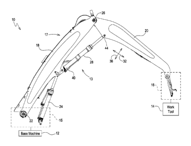
[006] FIG. 1 is right-hand side elevation view showing a work machine
comprising
a base machine (shown diagrammatically), a boom apparatus attached to the base
machine, and a work tool (shown diagrammatically) attached to the boom
apparatus;
[007] FIG. 2 is a perspective view showing an anchor body fixed to a second of
two booms of a boom structure of the boom apparatus;
[008] FIG. 3 is a perspective view showing a left-hand side of the second
boom;
[009] FIG. 4 is a bottom view showing the anchor body fixed to the second
boom;
[010] FIG. 5 is a sectional view taken along lines 5-5 showing at least one
flexible
line spaced apart from an end portion of a fluid cylinder by a barrier;
[011] FIG. 6 is a bottom view showing the anchor body;
[012] FIG. 7 is a perspective view of the anchor body; and
[013] FIG. 8 is a right-hand side elevation view of the anchor body.
Detailed Description of the Drawinds
[014] Referring to FIG. 1, a work machine 10 comprises, for example, a base
machine 12, a boom apparatus 13, and a work tool 14. The work machine 10 may
be any of a variety of work machines. For example, the work machine 10 may be
a
forestry machine. In such a case, the base machine 12 may be a tracked or
wheeled base machine, and the work tool 14 may be a forestry attachment, such
as,
for example, a disk saw felling head, a harvesting head, or a debarking head,
to
name but a few forestry attachments. The boom apparatus 13 is illustrated, for
example, as a boom apparatus for a forestry machine, it being understood that
the
boom apparatus 13 may be configured for a wide variety of work machines.
[015] The boom apparatus 13 comprises, for example, a first end portion 15 and
a
second end portion 16. The first end portion 15 is attached to the base
machine 12,
and the work tool 14 is attached to the second end portion 16.
[016] The boom apparatus 13 comprises, for example, a boom structure 17.
Exemplarily, the boom structure 17 comprises a first boom 18 and a second boom
20. The first boom 18 is attached pivotally to the base machine 12 for pivotal
2
CA 02893693 2015-06-03
WO 2014/088609
PCT/1JS2013/024146
movement of the first boom 18, and thus the boom structure 17, relative to the
base
machine 12 about a first boom pivot axis 22. The second boom 20 is attached
pivotally to the first boom 18 for pivotal movement of the second boom 20
relative to
the first boom 18 about a second boom pivot axis 26.
W7] The boom apparatus 13 comprises, for example, two fluid cylinders 24
(e.g.,
hydraulic cylinders). The cylinders 24 are attached pivotally to the base
machine 12
and the first boom 18 to raise and lower the first boom 18, and thus the boom
structure 17, relative to the base machine 12 about the first boom pivot axis
22.
(0181 The boom apparatus 13 comprises, for example, a fluid cylinder 28, in
the
form of, for example, a hydraulic cylinder. The cylinder 28 is attached
pivotally to the
first boom 18 and the second boom 20 to pivot the second boom 20 relative to
the
first boom 18. The cylinder 28 is so attached to pivot the second boom 20
relative to
the first boom 18 about the second boom pivot axis 26.
(0191 Referring to FIGS. 2-5, the second boom 20 has a first, longitudinal
dimension 32, a second, lateral dimension 34, and a third dimension 36. The
first,
second, and third dimensions 32, 34, 36 are perpendicular to one another.
(020] The boom apparatus 13 comprises, for example, a monolithic (one-piece)
anchor body 30. The anchor body 30 is fixed (e.g., welded) to the second boom
20.
The anchor body 30 comprises, for example, a hinge point 38. The cylinder 28
comprises, for example, a first end portion 40 attached pivotally to the first
boom 18
and a second end portion 42 (e.g., eye of rod end portion) attached pivotally
to the
anchor body 30 and thus the second boom 20. The second an end portion 42 is
pinned to the second boom 20. The hinge point 38 and the second end portion 42
are included in a hinge 44 of the boom apparatus 13 so as to be pinned to one
another.
[021] The anchor body 30 comprises, for example, a barrier 46 positioned
between the second end portion 42 and the second boom 20 relative to the third
dimension 36. The boom apparatus 13 comprises, for example, at least one
flexible
line 48 routed externally of the second boom 20 through a passageway 50
positioned between the barrier 46 and the second boom 20 relative to the third
dimension 36 such that the barrier 46 spaces the at least one flexible line 48
apart
from the second end portion 42 (FIG. 5) so as to prevent abrasion of the at
least one
flexible line 48 by the second end portion 42 during pivotal movement of the
second
3
CA 02893693 2015-06-03
WO 2014/088609
PCT/1JS2013/024146
boom 20 relative to the first boom 18 about the second boom pivot axis 26.
[022] Illustratively, the anchor body 30 is a monolithic structure. For
example, the
anchor body 30 is a casting made, for example, of cast steel. In other
examples, it
may be a weldment, or have its components otherwise attached to one another.
[023] The anchor body 30 comprises, for example, a frame 52. The frame 52 is
fixed (e.g., welded) to the second boom 20, such that the frame 52 mates with
the
second boom 20. The hinge point 38 and the barrier 46 are mounted to the frame
52. The frame 52 and the barrier 46 cooperate to define the passageway 50.
[024] Referring to FIGS. 6-8, the frame 52 comprises a first frame side wall
54. a
second frame side wall 56 spaced apart from the first frame side wall 54
relative to
the second dimension 34, and a support wall 58 attached to the first and
second
frame side walls 54, 56 (e.g., integrated with the walls 54, 56 in a casting).
The
hinge point 38 and the barrier 46 are mounted to the first and second frame
side
walls 54, 56 (e.g., integrated with the walls 54, 56 in a casting).
[025] Referring to FIGS. 2-4, the second boom 20 comprises, for example, a
first
boom side wall 66, a second boom side wall 68, a first intermediate boom wall
70
(e.g., bottom boom wall), and a second intermediate boom wall 72 (e.g., top
boom
wall). The first and second boom intermediate boom walls 70, 72 are spaced
apart
from one another relative to the third dimension 36 and are attached to (e.g.,
welded)
and positioned between and the first and second boom side walls 66. 68
relative to
the second dimension 34. The second boom side wall 68 is spaced apart from the
first boom side wall 68 relative to the second dimension 34 by use of the
first and
second boom intermediate boom walls 70, 72. The second boom 20 is thus
configured, for example, as a box boom. The first boom 18 is also configured,
for
example, as a box boom.
[026] Referring to FIGS. 2, 4, and 5, the second boom 20 comprises, for
example,
a first lug 74 and a second lug 76. Exemplarily, the first boom side wall 66
comprises the first lug 74, and the second boom side wall 68 comprises the
second
lug 76. The first frame side wall 54 is mounted (e.g., welded) to the first
lug 74. The
second frame side wall 56 is mounted (e.g., welded) to the second lug 76.
[027] Referring to FIGS. 2 and 4-6, the hinge point 38 comprises, for example,
a
first barrel 60 and a second barrel 62. The second end portion 42 is
positioned
between the first and second barrels 60, 62 relative to the second dimension
34.
4
CA 02893693 2015-06-03
WO 2014/088609
PCT/1JS2013/024146
Exemplarily, the hinge 44 comprises a pin 64.
[028] The hinge point 38 is mounted to the first and second frame side walls
54,
56. The first and second barrels 60, 62 are mounted respectively to the first
and
second frame side walls 54, 56 (e.g., integrated with the walls 54, 56 in a
casting).
The first and second barrels 60, 62 and the end portion 42 are positioned
between
the first and second lugs 74, 76 relative to the second dimension 34, such
that the
pin 64 is positioned in the first and second barrels 60, 62, the end portion
42, a hole
78 of the first lug 74, and a hole 80 of the second lug 76. The pin 64 is
flagged to the
second frame side wall 56 against movement relative thereto.
[029] Referring to FIGS. 6-8, each of the first frame side wall 54 and the
second
frame side wall 56 is generally triangle-shaped. The first barrel 60 provides
a vertex
82 of the first frame side wall 54. The second barrel 62 provides a vertex 82
of the
second frame side wall 56. The support wall 58 is mounted (e.g., welded) to
the first
intermediate boom wall 70, and attached to a first edge 84 of the first frame
side wall
54 opposite to the vertex 82 of the first frame side wall 54 and to a second
edge 84
of the second frame side wall 56 opposite to the vertex 82 of the second frame
side
wall 56.
[030] The anchor body 30 is symmetrical. It is symmetrical relative to a first
plane
of symmetry 98 and a second plane of symmetry 100. Each of the hinge point 38,
the barrier 46, and the frame 52 is symmetrical relative to the planes of
symmetry 98.
100.
[031] Referring to FIGS. 4-6, the support wall 58 is mounted (e.g., welded) to
the
first intermediate boom wall 70. The support wall 58 is, for example, H-
shaped. In
such a case, the support wall 58 comprises, for example, four legs 86 and a
bridge
88 interconnecting the four legs 86. The four legs 86 are positioned on the
first
intermediate boom wall 70. Two of the legs 86 extend along the corner between
the
first frame side wall 54 and the first intermediate boom wall 70 so as to be
mounted
(e.g., welded) to the walls 54, 70, and two of the legs 86 extend along the
corner
between the second frame side wall 56 and the first intermediate boom wall 70
so as
to be mounted (e.g., welded) to the walls 56, 70. The bridge 88 is mounted
(e.g.,
welded) to the first intermediate boom wall 70.
[032] Referring to FIG. 6, the barrier 46 is mounted to the first and second
frame
side walls 54, 56. The barrier 46 comprises, for example, a first barrier
portion 90
CA 02893693 2015-06-03
WO 2014/088609
PCT/1JS2013/024146
and a second barrier portion 92. The first and second barrier portions 90, 92
are
mounted respectively to the first and second frame side walls 54, 56 (e.g.,
integrated
with the walls 54, 56 in a casting).
[033] The hinge point 38 is positioned, for example, between the first and
second
barrier portions 90, 92 relative to the first dimension 32. The first and
second barrels
60, 62 are positioned between the first and barrier portions 90, 92 relative
to the first
dimension 32.
[034] The barrier 46 is positioned, for example, between the support wall 58
and
the hinge point 38 relative to the third dimension 36. The first and second
barrier
portions 90, 92 are positioned between the support wall 58 and the first and
second
barrels 60, 62 relative to the third dimension 36.
[035] Each of the first and second barrier portions 90, 92 is, for example,
generally
C-shaped. Each of the first and second barrier portions 90, 92 comprises, for
example, a post 94 extending lengthwise in the second dimension 34, a first
arm 96
extending from the post 94 and attached to the first frame side wall 54 and
the first
barrel 60 (e.g., integrated with the wall 54 and barrel 60), and a second arm
96
extending from the post 94 and attached to the second frame side wall 56 and
the
second barrel 62 (e.g., integrated with the wall 56 and barrel 62).
[036] The first and second frame side walls 54, 56, the support wall 58, and
the
barrier 46 cooperate, for example, to define the passageway 50. The bridge 88
and
the first and second barrier portions 90, 92 define portions of the passageway
50.
[037] Referring to FIG. 5, at least one flexible line 48 is routed through the
passageway 50. Exemplarily, there are a number of flexible lines 48 routed
through
the passageway 50. Each flexible line 48 may be, for example, a hydraulic
line, an
electrical line, or a grease line. One or more of the lines may be for an
attachment
(e.g., forestry attachment) to an end of the boom structure 17.
[038] The barrier 46 spaces the flexible lines 48 apart from the hinge 44 so
as to
prevent abrasion of the lines 48 during pivotal movement of the second boom 20
relative to the first boom 18. The barrier 46 spaces the flexible lines 48
apart from
the end portion 42 so as to prevent abrasion of the flexible lines 48 by the
end
portion 42 during such pivotal movement. The barrier 46 prevents sagging or
flexing
of the lines 48 into the hinge 44. The anchor body 30 promotes compactness of
the
envelope of the boom apparatus 13 and simplicity and tidiness in routing of
the lines
6
48.
[039] Welds and any threads have not been shown in the drawings for
simplification
of illustration, it being understood that it would be well within the skill of
one of ordinary
skill in the art to provide those features without undue experimentation.
[040] While the disclosure has been illustrated and described in detail in
the
drawings and foregoing description, such illustration and description is to be
considered
as exemplary and not restrictive in character, it being understood that
illustrative
embodiment(s) have been shown and described and that all changes and
modifications
that come within the spirit of the disclosure are desired to be protected. It
will be noted
that alternative embodiments of the present disclosure may not include all of
the features
described yet still benefit from at least some of the advantages of such
features. Those
of ordinary skill in the art may readily devise their own implementations that
incorporate
one or more of the features of the present disclosure and fall within the
spirit and scope
of the appended claims.
7
CA 2893693 2019-01-02