Note: Descriptions are shown in the official language in which they were submitted.
CA 02893774 2015-06-04
WO 2014/089608 PCT/AU2013/001433
1
TITLE
SYSTEM AND METHOD FOR REFUELLING COMPRESSED GAS
PRESSURE VESSELS USING A LIQUID PISTON
FIELD OF THE INVENTION
This invention relates generally to a compressed gas transfer
system. In particular, the invention relates to a compressed natural gas
(CNG) transfer system including a method of storing and delivering CNG
at a controlled pressure using a liquid piston.
BACKGROUND OF THE INVENTION
Natural gas fuels are relatively environmentally friendly for use in
vehicles, and hence there is support by environmental groups and
governments for the use of natural gas fuels in vehicle applications.
Natural gas based fuels are commonly found in three forms: Compressed
Natural Gas (CNG), Liquefied Natural Gas (LNG) and a derivative of
natural gas called Liquefied Petroleum Gas (LPG).
Natural gas fuelled vehicles have impressive environmental .
credentials as they generally emit very low levels of SO2 (sulphur dioxide),
soot and other particulate matter. Compared to gasoline and diesel
powered vehicles, CO2 (carbon dioxide) emissions of natural gas fuelled
vehicles are often low due to a more favourable carbon-hydrogen ratio
found in natural gas. Natural gas vehicles come in a variety of forms, from
small cars to buses and increasingly to trucks in a variety of sizes. Natural
gas fuels also provide engines with a longer service life and lower
maintenance costs. Further, CNG is the least expensive alternative fuel
when comparing equal amounts of fuel energy. Still further, natural gas
fuels can be combined with other fuels, such as diesel, to provide similar
benefits mentioned above.
A key factor limiting the use of natural gas in vehicles is the storage
of the natural gas fuel. In the case of CNG and LNG, the fuel tanks are
generally expensive, large and cumbersome relative to tanks required for
CA 02893774 2015-06-04
WO 2014/089608
PCT/M12013/001433
2
conventional liquid fuels having equivalent energy content. In addition, the
relative lack of wide availability of CNG and LNG refuelling facilities, and
the cost of LNG, add further limitations on the use of natural gas as a
motor vehicle fuel. Further, in the case of LNG, the cost and complexity of
producing LNG and issues associated with storing a cryogenic liquid on a
vehicle further limits the widespread adoption of this fuel.
Some of the above issues are mitigated when using LPG and this
fuel is widely used in high mileage motor cars such as taxis. However,
cost versus benefit comparisons are often not favourable in the case of
private motor cars. Issues associated with the size and shape of the fuel
tank, the cost variability of LPG and the sometimes limited supply mean
that LPG also has significant disadvantages that limit its widespread
adoption. In summary, unless there is massive investment in a network of
LNG plants around major transport hubs, CNG is the only feasible form of
natural gas that is likely to be widely utilised in the near future.
Further; although LNG has had some success as a liquid fuel
replacement in some regions of the world, the lack of availability of LNG
and its high cost means that in many regions of the world it is not feasible
to use LNG. In the case of CNG, it also has had some success as a liquid
fuel replacement but almost exclusively in spark ignition engines utilising
the low pressure carburetted port injection induction technology. This
application is popular in government bus fleets around the world where the
cleaner burning natural fuel is used in a spark ignition engine fitted in
place of a conventional diesel engine. The application is usually a limited
range fleet and includes a buffer CNG fill strategy with overnight refuelling
of the fleet.
However, the circumstances for broad implementation of CNG in
large vehicles are limited by this buffer fill strategy, which essentially
delivers gas at only the capacity of the compressor with any gas storage
acting as a buffer to minimise compressor on/off cycling. Thus CNG has
been seen as having limitations due to the size of incoming gas
connections and electrical power requirements to meet intermittent and
CA 02893774 2015-06-04
WO 2014/089608
PCT/AU2013/001433
3
peak demands at refuelling stations.
For example, a typical requirement for refuelling a CNG vehicle is
diesel 'gallons equivalent per minute. If 4 vehicles were to be refuelled
simultaneously, on a site with 4 dispensers, this would require up to
5 2000kW of
compression and a correspondingly large gas interconnection,
if using typical US industry CNG industrial gas supply connection
pressures.
US Patent No. 4,805,674 to Knowlton discloses a "fast-fill" natural
gas storage and retrieval system that overcomes some of the above
10 described
problems regarding the need for significant energy to compress
natural gas from the relatively low pressure of utility supply lines to the on-
vehicle storage pressures of around 3600 psig. Knowlton uses a natural
gas displacing liquid to effectively vary the volume of a primary CNG
storage vessel.
However, the disclosure of Knowlton presents several problems
regarding gas loss and gas contamination. For example, if the displacing
liquid is an aqueous liquid, the CNG can become contaminated with water,
which requires expensive gas drying processes when the gas is expelled
for use. Further, alternative displacing liquids can become contaminated
by the CNG dissolving into the liquid. The dissolved CNG then can be lost
when the displacing liquid is removed from the CNG storage vessel to a
low-pressure liquid storage tank.
Ionic liquids, i.e., a salt in liquid state with low vapour pressure,
have been trialled with CNG displacement in micro scale compressors, but
these solutions are expensive, often flammable, and have high
environmental toxicity - and thus do not scale to large installations.
Further various solutions of hydrocarbon type oils have been
trialled with poor results, as these solutions take up a substantial quantity
of gas in solution, which presents a problem with gas recovery and
otherwise loss when the solution is returned to a low-pressure liquid
storage tank.
Also, gas and liquid isolation inside pressure vessels has been
CA 02893774 2015-06-04
WO 2014/089608
PCT/AU2013/001433
4
attempted using physical bladders or mechanical pistons; however
problems with cost, complexity, scaling fabrication and maintenance have
made these potential solutions problematic.
Therefore, there is a need for an improved system and method for
refuelling compressed gas pressure vessels.
OBJECT OF THE INVENTION
It is an object of some embodiments of the present invention to
provide consumers with improvements and advantages over the above
described prior art, and/or overcome and alleviate one or more of the
above described disadvantages of the prior art, and/or provide a useful
commercial choice.
SUMMARY OF THE INVENTION
In one form, although not necessarily the only or broadest form, the
invention resides in a pressure vessel refuelling system comprising:
a pressure vessel having a gas inlet/outlet port and a liquid
inlet/outlet port;
a first liquid at least partially filling the pressure vessel;
a liquid layer of a second liquid floating on top of the first liquid,
wherein the second liquid is immiscible with the first liquid;
a gas at least partially filling the pressure vessel above the liquid
layer of the second liquid, the gas in fluid communication with the gas
inlet/outlet; and
a pump in fluid communication with the liquid inlet/outlet of the
pressure vessel, whereby the first liquid can be pumped into the pressure
vessel.
Preferably, the gas is immiscible with the second liquid.
Preferably, the first liquid is an aqueous solution.
Preferably, the first liquid is an aqueous salt solution.
Preferably, the second liquid is an oil.
Preferably, the second liquid is a mineral oil.
5
Preferably, a volume of the liquid layer of the second liquid
comprises less than 5% of the volume of the pressure vessel.
Preferably, a volume of the liquid layer of the second liquid
comprises less than 1% of the volume of the pressure vessel.
Preferably, the system further comprises a liquid storage tank in fluid
communication with the liquid inlet/outlet of the pressure vessel, wherein
the pump pumps the first liquid from the liquid storage tank and into the
pressure vessel.
Preferably, the system further comprises a compressor in fluid
communication with the gas inlet/outlet port, whereby the gas can be
received from a supply line and compressed into the pressure vessel.
Preferably, a coalescer filter is in fluid communication with the
pressure vessel and functions as a filter to remove traces of the second
liquid from the gas after the gas exits the pressure vessel and returns the
second liquid to the pressure vessel.
Preferably, the system further comprises a plurality of pressure
vessels, each pressure vessel having the first liquid at least partially
filling
the pressure vessel; a liquid layer of the second liquid floating on top of
the
first liquid in each pressure vessel; and the gas at least partially filling
each
pressure vessel above the liquid layer of the second liquid, the gas in fluid
communication with a gas inlet/outlet.
Preferably, the plurality of pressure vessels are adapted be filled
simultaneously with the gas from a single gas line connected in parallel to
each vessel in the plurality of vessels.
Preferably, each vessel in the plurality of pressure vessels is in fluid
communication with the pump and with the liquid storage tank.
In accordance with an aspect of an embodiment, there is provided a
pressure vessel refueling system, comprising: a compressed natural gas
(CNG) refueling pressure vessel having a gas inlet/outlet port and a liquid
inlet/outlet port; an aqueous liquid comprising an aqueous salt solution
acting as both an anti-freeze and hydrate formation suppressant at least
partially filling the pressure vessel; a liquid layer of oil floating on top
of the
aqueous liquid, wherein the oil is immiscible with the aqueous liquid; natural
gas at least partially filling the pressure vessel above the liquid layer of
oil,
Date Recue/Date Received 2020-10-26
5a
the natural gas in fluid communication with the gas inlet/outlet, and wherein
the natural gas is immiscible with the oil; a pump in fluid communication
with the liquid inlet/outlet of the pressure vessel, whereby the aqueous
liquid can be pumped into the pressure vessel; and a compressor in fluid
communication with the gas inlet/outlet port, whereby the natural gas can
be received from a natural gas supply line and compressed into the
pressure vessel; wherein a coalescing filter is in fluid communication with
the pressure vessel and functions as a filter to remove particles of the oil
from the natural gas after the natural gas exits the pressure vessel and
returns the oil to the pressure vessel.
In accordance with another aspect of an embodiment, there is
provided a pressure vessel refueling system, comprising: a pressure vessel
having a gas inlet/outlet port and a liquid inlet/outlet port; a first liquid
at
least partially filling the pressure vessel; a liquid layer of a second liquid
floating on top of the first liquid, wherein the second liquid is immiscible
with
the first liquid; a natural gas at least partially filling the pressure vessel
above the liquid layer of the second liquid, the gas in fluid communication
with the gas inlet/outlet; a pump in fluid communication with the liquid
inlet/outlet of the pressure vessel, whereby the first liquid can be pumped
into the pressure vessel; a compressor in fluid communication with the gas
inlet/outlet port, whereby the natural gas can be received from a natural gas
supply line and compressed into the pressure vessel; and a coalescing filter
in fluid communication with the pressure vessel and functioning as a filter
to remove particles of the second liquid from the natural gas after the
natural gas exits the pressure vessel and returns the second liquid to the
pressure vessel.
BRIEF DESCRIPTION OF THE DRAWINGS
To assist in understanding the invention and to enable a person
skilled in the art to put the invention into practical effect, preferred
embodiments of the invention are described below by way of example only
with reference to the accompanying drawings, in which:
Date Recue/Date Received 2020-10-26
CA 02893774 2015-06-04
WO 2014/089608
PCT/AU2013/001433
6
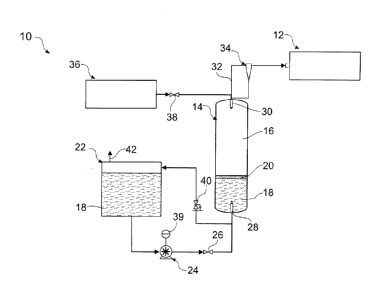
FIG. 1 illustrates a pressure vessel refuelling system that supplies
gas at high pressure to a gas dispenser, according to an embodiment of
the present invention.
FIG. 2 is a further illustration of the pressure vessel refuelling
system of FIG. 1, wherein the CNG storage vessel is almost empty of gas,
according to an embodiment of the present invention.
FIG. 3 is yet a further illustration of the pressure vessel refuelling
system of FIG. 1, wherein the CNG storage vessel is almost entirely full of
gas.
Those skilled in the art will appreciate that minor deviations from
the layout of components as illustrated in the drawings will not detract
from the proper functioning of the disclosed embodiments of the present
invention.
DETAILED DESCRIPTION OF THE PREFERRED EMBODIMENT
Embodiments of the present invention comprise systems and
methods for refuelling compressed gas pressure vessels using a liquid
piston. Elements of the invention are illuetrated in concise outline form in
the drawings, showing only those specific details that are necessary to the
understanding of the embodiments of the present invention, but so as not
to clutter the disclosure with excessive detail that will be obvious to those
of ordinary skill in the art in light of the present description.
In this patent specification, adjectives such as first and second, left
and right, front and back, top and bottom, etc., are used solely to define
one element or method step from another element or method step without
necessarily requiring a specific relative position or sequence that is
described by the adjectives. Words such as "comprises" or "includes" are
not used to define an exclusive set of elements or method steps. Rather,
such words merely define a minimum set of elements or method steps
included in a particular embodiment of the present invention.
According to one aspect, the invention includes a pressure vessel
refuelling system. The system includes a pressure vessel having a gas
CA 02893774 2015-06-04
WO 2014/089608
PCT/AU2013/001433
7
inlet/outlet port and a liquid inlet/outlet port, a first liquid at least
partially
filling the pressure vessel, and a liquid layer of a second liquid floating on
top of the first liquid. The first liquid is non-miscible with the second
liquid,
such that the liquid layer forms a "liquid piston" that is displaced up and
down in the vessel as gas is added to and then expelled from the vessel.
A liquid storage tank is in fluid communication with the liquid inlet/outlet
of
the pressure vessel, and a pump is in fluid communication with the liquid
storage tank. The first liquid thus can be pumped from the liquid storage
tank into the pressure vessel to maintain the pressure vessel at a constant
pressure as the gas is expelled from the vessel.
Advantages of the present invention include enabling fast fill
refuelling methods of CNG fuel tanks using reduced size primary
compression and storage. The storage is maintained at a constant
pressure as gas is discharged, providing opportunity for consistent high
pressure filling of CNG fuel tanks. Other advantages include reducing a
heat rise of the primary storage vessel during its refilling, by avoiding the
heat of recompression in the vessel with the application of a back
pressure. Further, due to the ability to maintain a constant high pressure
in the primary storage vessel during refuelling, a greater number of vehicle
fuel tanks can be refuelled simultaneously and faster, with lower peak
power requirements, as the CNG is already compressed/produced and is
simply transferred from storage to the vehicle fuel tank ¨ thus minimising
the size of gas and electric utility connections and the associated demand
charges.
In this specification CNG cylinders that supply or store gaseous fuel
are synonymously referred to as tanks, vessels, pressure vessels, CNG
cylinders and cylinders.
FIG. 1 illustrates a pressure vessel refuelling system 10 that
supplies gas at high pressure to a gas dispenser 12. The system 10
includes a CNG primary storage vessel 14 that is partially filled with
natural gas 16 and partially filled with an aqueous liquid 18. A thin layer of
a second liquid in the form of an oil 20 floats on top of the aqueous liquid
8
18. Because the oil 20 is both immiscible with the aqueous liquid 18 and is
less dense than the aqueous liquid 18, the layer of oil 20 functions as a
"liquid piston" that moves up and down inside the vessel 14 as a volume of
the aqueous liquid 18 in the vessel 14 changes.
The floating layer of oil 20 creates a barrier that prevents the
aqueous liquid 18 from contacting and evaporating into the natural gas 16.
In some cases the oil 20 may become saturated with the natural gas 16.
However, because the oil 20 does not leave the storage vessel 14, and
because only a thin layer of oil 20 is required (which becomes saturated
with natural gas on initial fill), insignificant natural gas 16 is not
available,
or is lost from storage.
The system 10 further includes a liquid storage tank 22 and a pump
24. In use, for example when a CNG vehicle or a plurality of CNG vehicles
are being refuelled from the gas dispenser 12, the pump 24 pumps the
aqueous liquid 18 through a check valve 26 and through a lower float valve
28 in a lower inlet/outlet port and into the vessel 14. Simultaneously, the
natural gas 16 flows through an upper float valve 30 in an upper inlet/outlet
port, through a gas line 32 and to the dispenser 12. As the aqueous liquid
18 enters the vessel 14 and the gas 16 exits the vessel 14, the layer of oil
20 rises in the vessel 14 and maintains a barrier between the gas 16 and
the aqueous liquid 18.
The lower float valve 28 functions to prevent the gas 16 from exiting
through the bottom of the vessel 14 in the event that all of the aqueous
liquid 18 is drained from the vessel 14. Similarly, the upper float valve 30
functions to prevent the aqueous liquid 18 from exiting through the top of
the vessel 14 in the event that all of the gas 16 is pushed out of the vessel
14 by the layer of oil 20 rising to the top of the vessel 14. As an example,
the lower float valve 28 and the upper float valve 30 can function as
described in international patent application no. PCT/AU2012/000265,
titled Compressed Natural Gas Tank Float Valve System and Method
published on 20 September 2012 under International Publication No.
W02012/122599.
CA 2893774 2020-03-27
9
During the refuelling process, for example of a vehicle fuel tank
connected to the dispenser 12, a coalescer filter 34 functions as a filter to
remove traces of the oil 20 from the gas 16 before such traces reach the
dispenser 12. It is normal in the CNG industry to use such filtration
methods to remove trace compressor oil. However,
unlike in a
compressor, the oil-gas interface is essentially static and does not entrain
oil in the gas. Thus the layer of oil 20 enables a significantly more
efficient
gas transfer system, even though traces of the oil 20 may require filtering
by the coalescer 34.
When re-filling the CNG storage vessel 14 with natural gas 16, or
while re-fuelling a vehicle using the dispenser 12, a gas compressor 36
can be activated to allow the gas 16 to be compressed and supplied via a
check valve 38 from a natural gas supply line (not shown) either into the
storage vessel 14 or directly to the dispenser 12.
A pressure controller 39 enables the pump 24 to be activated
automatically when a pressure drop is detected in the storage vessel 14.
Working simultaneously with the gas compressor 36, the pump 24 enables
a high flow rate of gas to be delivered to the dispenser 12; that in turn
enables, for example, multiple CNG fuel tanks/vehicles to be refuelled
simultaneously from the dispenser 12 or a plurality of dispensers.
By displacing the already compressed natural gas 16 from storage
14 at constant high pressure to the dispenser 12, the steady state power
needed by the system 10 to maintain a constant maximum output of gas
16 from the dispenser 12 can be reduced by up to an order of magnitude
when compared to using online CNG compression to meet the required
delivery rate, from conventional industrial natural gas supply pressures.
That means, for example, when refuelling several CNG vehicles
simultaneously from the dispenser 12, the compressor 36 can be much
smaller than would be required in a comparable refuelling system that did
not maintain or use a CNG storage vessel at a constant pressure using
liquid displacement of the stored gas. According to the present invention
CA 2893774 2020-03-27
CA 02893774 2015-06-04
WO 2014/089608
PCT/AU2013/001433
the full amount of stored gas is available and deliverable at several times
the rate that would otherwise be possible using the equivalent power
applied only to a gas compressor.
During refilling of the vessel 14 with the gas 16, as the gas 16 is
5 compressed into
the vessel 14, the layer of oil 20 applies pressure to the
aqueous liquid 18 and opens a back pressure valve 40. The aqueous
liquid 18 then flows through the back pressure valve 40 and back into the
liquid storage tank 22. As the liquid level rises in the storage tank 22, air
in the tank 22 is vented to atmosphere through a vapour vent 42.
10 FIG. 2 is a
further illustration of the pressure vessel refuelling
system 10, wherein the CNG storage vessel 14 is almost empty of gas 16.
A considerable volume of aqueous solution 18 has therefore been
pumped by the pump 24 from the liquid storage tank 22 into the vessel 14,
enabling the small volume of gas 16 in the vessel 14 to remain at or near
a full operating pressure, such as 5000 psig.
As the layer of oil 20 reaches the upper float valve 30, the pump 24
is deactivated and the storage vessel 14 is considered to be empty of gas
16 and in need of re-filling. A volumetric analysis of the flow through the
pump 24 can be used to determine that the vessel 14 is nearly empty of
gas 16 and full of the aqueous solution 18. However, the upper float
valve 30 can be used as a safety mechanism to ensure that the layer of oil
20 is not pumped out of the storage vessel 14.
FIG. 3 is yet a further illustration of the pressure vessel refuelling
system 10, wherein the CNG storage vessel 14 is almost entirely full of
gas 16. As the layer of oil 20 drops to the level of the lower float valve 28,
the storage vessel 14 is considered to be full of gas 16. A volumetric
analysis of the volume of aqueous solution 18 in the storage tank 22 can
be used to determine that the vessel 14 is full of gas 16 and nearly empty
of the aqueous solution 18. However, the lower float valve 28 can be
used as a safety mechanism to ensure that the layer of oil 20 is not
pumped out of the storage vessel 14 and into the storage tank 22. The
lower float valve includes a plug (not shown) that sinks in the oil 20 but
. CA 02893774 2015-06-04
WO 2014/089608
PCT/M12013/001433
11
floats in the aqueous solution 18 - thus retaining the oil 20 in the vessel
14.
According to some embodiments, the aqueous solution 18 is non-
gas miscible and the oil 20 is immiscible in water. The aqueous solution
18 thus can move in and out of the pressurized storage vessel 14 without
carrying dissolved gas 16. The aqueous solution 18 can be, for example,
a salt solution to act as an anti-freeze and hydrate formation suppressant
to prevent solids forming in the system 10. Also, various types of non-
water miscible fluids can be used as the oil 20, such as various mineral
:10 oils or organic oils.
Those skilled in the art will further appreciate that the single storage
vessel 14 can be replaced by a plurality of vessels operating in parallel
both when being refilled with the gas 16 and when discharging the gas 16.
Thus each pressure vessel in the plurality of vessels will include a layer of
the oil 20 floating on top of the aqueous solution 18, and will operate as
described herein concerning the vessel 14. Use of such a plurality of
vessels enables significantly greater gas storage capacity in a single
system 10.
In summary, advantages of the present invention include enabling
fast fill refuelling methods of CNG fuel tanks by utilising the full capacity
of
the installed storage and delivering that storage using substantially less
power than that required by equivalent gas compression plant to meet
=
peak demands. The storage is maintained at a constant pressure as gas
is discharged enabling complete filling of tanks/vehicles. The system thus
minimises the size of gas and electric utility connections and the
associated demand charges. This leverages the delivery capacity of CNG
fuelling stations that are limited by utility connections and can make
sizable CNG stations feasible where only limited utility connections exist.
Also, the present invention can eliminate the issue of in cylinder
recompression heating inside CNG storage cylinders when filling the
storage, enabling consistent filling to a pressure vessel's standard ambient
temperature pressure rating at design pressures. This provides increased
CA 02893774 2015-06-04
WO 2014/089608
PCT/AU2013/001433
12
CNG storage or the opportunity to reduce storage vessel sizes.
Also, eliminating the heat of compression inside a CNG storage
vessel during re-filling increases safety, particularly by preventing
transient
temperature excursions during re-filling of storage, thereby allowing for the
potential to redesign composite storage vessel cylinders to be lower cost.
The above description of various embodiments of the present
invention is provided for purposes of description to one of ordinary skill in
the related art. It is not intended to be exhaustive or to limit the invention
to a single disclosed embodiment. As mentioned above, numerous
alternatives and variations to the present invention will be apparent to
those skilled in the art of the above teaching. Accordingly, while some
alternative embodiments have been discussed specifically, other
embodiments will be apparent or relatively easily developed by those of
ordinary skill in the art. Accordingly, this patent specification is intended
to
embrace all alternatives, modifications and variations of the present
invention that have been discussed herein, and other embodiments that
fall within the spirit and scope of the above described invention.