Note: Descriptions are shown in the official language in which they were submitted.
BACKGROUND
Typically the knife on harvest headers comprises a knife bar extending along
the front
lower edge of the header, with a plurality of triangular knife sections
attached to the bar
such that the apex of the triangle extends forward from the bar. The exposed
side edges
of the knife sections are sharpened. Guards are attached to the front lower
edge of the
header and serve to protect the knife sections from breakage when contacting
stones and
like obstructions. The guards comprise pointed guard fingers extending
forward, and the
knife moves back and forth along the edge of the header in a slot cut
laterally through the
guard fingers. In addition to protecting the knife, the guard fingers also
enable the knife
sections to cut the crop. As the knife section moves back and forth it pushes
crop against
the sides of those portions of the guard finger that are above and below the
slot, shearing
the crop stalks.
SUMMARY OF THE INVENTION
The present disclosure provides a harvest header apparatus that overcomes
problems in
the prior art.
In inter-seeded crops a first crop, such as winter wheat, is planted at a
fairly wide row
CA 02894100 2015-06-11
spacing of about 20-30 inches, and when that crop emerges, or in the spring, a
second
crop such as beans, is planted in rows midway between the rows of the first
crop. The
present disclosure provides a harvest header that allows cutting and
harvesting of the first
crop while preventing the second crop from being cut so that the second crop
can mature
and be harvested after the first crop is harvested.
DESCRIPTION OF THE DRAWINGS
While the invention is claimed in the concluding portions hereof, preferred
embodiments
are provided in the accompanying detailed description which may be best
understood in
conjunction with the accompanying diagrams where like parts in each of the
several
diagrams are labeled with like numbers, and where:
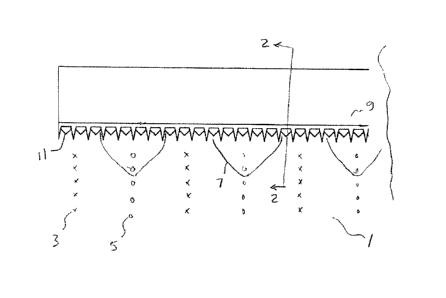
Fig. I is a schematic top view of a conventional harvest header with a
plurality of crop
shields of the present disclosure mounted thereon;
Fig. 2 is a schematic side view along line 2-2 in Fig. 1.
DETAILED DESCRIPTION OF THE ILLUSTRATED EMBODIMENTS
Fig. 1 schematically illustrates an embodiment of a harvest header apparatus I
of the
present disclosure travelling along a field to harvest plants of a first crop
3 while
preventing the header from cutting the plants of the second different crop 5
which are
growing in rows between rows of the first crop 3 as illustrated.
The apparatus 1 comprises a plurality of crop shields 7 mounted to a
conventional harvest
header 9. As seen in Fig. 2, the crop shields 7 extend from the header 9 under
the knife
II of the header and curve upward and forward from the knife 11. The crop
shields 7 are
spaced along the header 9 such that the crop shields 7 are aligned with the
rows of the
second crop 5, and as the header 9 moves along the rows the plants of crop 5
are pushed
CA 02894100 2015-06-11
downward by the crop shields 7 and prevented from contacting the knife II and
pass
under the header 9 without being cut.
The knife it is exposed in the spaces between the crop shields 7 and as the
header 9
moves along the rows the plants of crop 3 are cut and moved onto the header 9
and
harvested conventionally.
Thus the apparatus 1 harvests the first crop 3 and leaves the second crop 5
uncut and still
rooted and growing in the field. The second crop is pushed down but otherwise
not
harmed. In a typical crop situation the first crop will be a taller crop such
as winter wheat
which can be cut relatively high, while the second crop 5 will be a lower
growing crop
such as beans, lentils, or the like.
The crop shields 7 are somewhat flexible, typically made from stiff resilient
plastic sheet
material, and positioning is adjustable. The crop shields 7 can be configured
to engage
fastening devices used for attaching conventional crop lifters to the header 9
so that they
can be removed easily when not required.
Following the rows accurately can be readily accomplished by seeding and then
harvesting the crops using the GPS guidance systems coupled with automatic
steering
that are presently common in the agricultural industry. Bare tramlines could
be left in the
second crop where the combine travels.
The foregoing is considered as illustrative only of the principles of the
invention.
Further, since numerous changes and modifications will readily occur to those
skilled in
the art, it is not desired to limit the invention to the exact construction
and operation
shown and described, and accordingly, all such suitable changes or
modifications in
structure or operation which may be resorted to are intended to fall within
the scope of
the claimed invention.
3
