Note: Descriptions are shown in the official language in which they were submitted.
CA 02894128 2015-06-11
WIRELESS PERSONAL EVACUATION SYSTEM
Field of the Invention
[0001] This invention relates to alarm systems, and more particularly to
personal gas detection
alarm systems.
Background of the Invention
[0002] Gas detection in industry has followed recent technology developments
and has moved to
wireless detection systems. Currently there are a number of alarm systems
utilized in industry
to detect gas (i.e. determine if a gas release has occurred) and to then
indicate an alarm to
personnel. These systems can be both wired and wireless with the majority of
available
systems still using wired technologies.
[0003] As work sites become larger indicator alarms, both audible and visual,
become harder to
register for personnel living on site due to a number of factors, including
insulated trailers;
other noise such as television; radio communication issues; visual or hearing
impairment; and
personnel sleeping. Other factors that impair alarm recognition include the
visibility of
indicating lights; blowing snow/dust; sunlight; distance to on site offices
and
accommodations; and audibility of the alarm.
[0004] Current alarm system indicators include strobe lights/beacons; sirens;
buzzer alarms; air
horns; and alarm bars (i.e. sirens with strobe lights). The current alarm
systems main goal is
area alarm notification. Such systems are used in outdoor or plant settings.
Due to size and
design they do not provide an adequate means for an indoor personal evacuation
alarm.
[0005] An example of an alarm system in the art is EchoView HostTM provided by
Rae Systems
Inc. It is a battery operated handheld wireless device. EchoView Host is used
in conjunction
with personal gas detection monitors to display real time gas readings and
alarm status.
[0006] Currently there are no known universal systems to provide indoor
individual evacuation
notice to personnel living on site or near the job location.
{E6887428 DOCX, 1}
CA 02894128 2015-06-11
Summary of the Invention
[0007] The system according to the invention provides a universal indoor
personal evacuation
alarm for gas detection systems. The existing alarm facilitates the activation
of the personal
evacuation system.
[0008] The system according to the invention provides a personal evacuation
system in each of
the offices and accommodation trailers on a work site. The alarm will provide
both a visual
and audible notification to notify personnel. The visual alarm visually
notifies the personnel
of the area that a gas release was detected using a color coded series of
flashing LED lights
so an appropriate evacuation route can be selected. The system provides the
end user with an
evacuation system to ensure personnel have the ability to be notified
immediately in the
event of a potentially dangerous situation. The system may be used in the oil
and gas
industry during drilling and completion activities and has personnel safety as
the primary
objective.
[0009] A wireless personal evacuation device is provided, including: a
wireless receiver for
receiving signals related to a presence of gas and a location associated with
the gas presence;
a plurality of light emitting diodes; arranged in rows, the diodes in each row
having a
different color; an audio emitter; a control board for processing the signal;
wherein on receipt
of the signal, the control board actuates the diodes in the row corresponding
to the location.
The wireless personal evacuation device may be located in a different building
from the
location. The wireless personal evacuation device may include an audible alarm
actuated on
receipt of the signal. The
diodes may further indicate the device is powered. The
location may be associated with one of a plurality of zones and the diodes may
be arranged in
rows on the device, each row associated with one of the plurality of zones.
Each row of
diodes may be a different color.
[0010] A personal evacuation alarm system is provided, including: a gas
detection system; a
control panel in communication with the gas detection system, the control
panel including a
wireless control board and a plurality of alarm ports, each alarm port
connected to an outdoor
audio alarm; a plurality of personal devices in wireless communication with
the control
panel, each of the personal devices including a plurality of light emitting
diodes; and an
- 2 -
{ E6887428.DOCX, 11
CA 02894128 2015-06-11
audio emitter. The control panel may be configured to receive a signal from
the gas
detection system indicating a presence of gas and a zone associated with the
presence. The
plurality of light emitting diodes may be arranged in rows, each row
associated with a zone.
The control panel may also be configured to send a wireless signal to each of
the plurality of
personal devices, the signal including the zone associated with the gas
presence. Each of the
personal devices may be configured to actuate the row of light emitting diodes
associated
with the zone indicated in the received signal. The personal devices may be
positioned in
buildings different from the gas detection system and the control panel may be
further
configured to actuate a plurality of outdoor audio alarms on receipt of the
signal indicating
the presence of gas.
[0011] A method of providing a personal evacuation signal, including:
determining, by a gas
detection system, a presence of gas and a zone associated with a location of
the gas;
communicating the presence of gas and the zone via a wired connection to a
control panel;
communicating the presence of gas and the zone via a wireless connection to a
plurality of
personal devices; and emitting a visible and auditory signal from each of the
personal
devices. The personal devices may be located in buildings different from the
gas detection
system and the visible signal may include the actuation of a plurality of
light emitting diodes,
the light emitting diodes positioned in a row associated with the zone.
Description of the Figures
[0012] Figure 1A and 1B are front and sides views of an embodiment of a
wireless personal
evacuation system according to the invention.
[0013] Figure 2 is a block diagram showing the environment wherein an
embodiment of the
wireless personal evacuation system may operate.
[0014] Figure 3 is a block diagram showing the system according to the
invention
Detailed Description of the Invention
[0015] A detailed description of one or more embodiments of the invention is
provided below
along with accompanying figures that illustrate the principles of the
invention. The invention
- 3 -
{E6887428.DOCX, 11
CA 02894128 2015-06-11
is described in connection with RAI embodiments, but the invention is not
limited to any
embodiment. The scope of the invention is limited only by the claims and the
invention
encompasses numerous alternatives, modifications and equivalents. Numerous
specific
details are set forth in the following description in order to provide a
thorough understanding
of the invention. These details are provided for the purpose of example and
the invention
may be practiced according to the claims without some or all of these specific
details. For the
purpose of clarity, technical material that is known in the technical fields
related to the
invention has not been described in detail so that the invention is not
unnecessarily obscured.
[0016] The term "invention" and the like mean "the one or more inventions
disclosed in this
application", unless expressly specified otherwise.
[0017] The terms "an aspect", "an embodiment", "embodiment", "embodiments",
"the
embodiment", "the embodiments", "one or more embodiments", "some embodiments",
"certain embodiments", "one embodiment", "another embodiment" and the like
mean "one or
more (but not all) embodiments of the disclosed invention(s)", unless
expressly specified
otherwise.
[0018] A reference to "another embodiment" or "another aspect" in describing
an embodiment
does not imply that the referenced embodiment is mutually exclusive with
another
embodiment (e.g., an embodiment described before the referenced embodiment),
unless
expressly specified otherwise.
[0019] The terms "including", "comprising" and variations thereof mean
"including but not
limited to", unless expressly specified otherwise.
[0020] The terms "a", "an" and "the" mean "one or more", unless expressly
specified otherwise.
The term "plurality" means "two or more", unless expressly specified
otherwise. The term
"herein" means "in the present application, including anything which may be
incorporated by
reference", unless expressly specified otherwise.
[0021] The term "e.g." and like terms mean "for example", and thus does not
limit the term or
phrase it explains.
- 4 -
IL6887428.DOCX,
CA 02894128 2015-06-11
[0022] The term "respective" and like terms mean "taken individually". Thus if
two or more
things have "respective" characteriF tics, then each such thing has its own
characteristic, and
these characteristics can be different from each other but need not be. For
example, the
phrase "each of two machines has a respective function" means that the first
such machine
has a function and the second such machine has a function as well. The
function of the first
machine may or may not be the same as the function of the second machine.
[0023] Where two or more terms or phrases are synonymous (e.g., because of an
explicit
statement that the terms or phrases are synonymous), instances of one such
term/phrase does
not mean instances of another such term/phrase must have a different meaning.
For example,
where a statement renders the meaning of "including" to be synonymous with
"including but
not limited to", the mere usage of the phrase "including but not limited to"
does not mean that
the term "including" means something other than "including but not limited
to".
[0024] Neither the Title (set forth at the beginning of the first page of the
present application)
nor the Abstract (set forth at the end of the present application) is to be
taken as limiting in
any way as the scope of the disclosed invention(s). An Abstract has been
included in this
application merely because an Abstract of not more than 150 words is required
under 37
C.F.R. Section 1.72(b) or similar law in other jurisdictions. The title of the
present
application and headings of sections provided in the present application are
for convenience
only, and are not to be taken as limiting the disclosure in any way.
[0025] Numerous embodiments are described in the present application, and are
presented for
illustrative purposes only. The described embodiments are not, and are not
intended to be,
limiting in any sense. The presently disclosed invention(s) are widely
applicable to numerous
embodiments, as is readily apparent from the disclosure. One of ordinary skill
in the art will
recognize that the disclosed invention(s) may be practiced with various
modifications and
alterations, such as structural and logical modifications. Although particular
features of the
disclosed invention(s) may be described with reference to one or more
particular
embodiments and/or drawings, it should be understood that such features are
not limited to
usage in the one or more particular embodiments or drawings with reference to
which they
are described, unless expressly specified otherwise.
- 5 -
{E6887428.DOCX, 1}
CA 02894128 2015-06-11
[0026] No embodiment of method steps or product elements described in the
present application
constitutes the invention claimed herein, or is essential to the invention
claimed herein, or is
coextensive with the invention claii.ied herein, except where it is either
expressly stated to be
so in this specification or expressly recited in a claim.
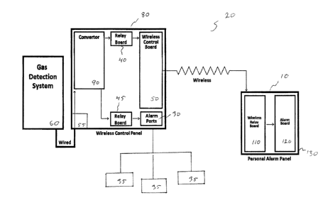
[0027] The system according to the invention, and as shown in Figure 3,
includes a universal
personal evacuation alarm 10 for use with an alarm system 20.
[0028] Alarm system 20 includes an alarm condition detection system 60. Alarm
condition
detection system 60 is a means for detecting a danger, such as a gas detection
system. Alarm
condition detection system 60 includes a plurality of alarm detectors which
are typically
positioned at different locations. For example, in the case depicted in Figure
2, alarms 70 are
located at locations such as the cellar, floor, at the mixer, and at the
shaker. More than one
alarm may be present at each of these locations.
[0029] Alarm condition detection system 60, such as a gas detection system, is
in
communication with control panel 80. Alarm condition detection system 60 may
be in wired
or wireless communication with control panel 80, but is more typically wired
to control panel
80.
[0030] Control panel 80 is normally located in a safe location, such as a
breathing air trailer 65.
Control panel 80 includes converter 90, for example that converts 120 Volt
power provided
by a standard electrical plug to tNN Ave (12) volts to power control panel 80.
Alternatively
control panel 80 may be powered by rechargeable batteries. Alarm ports 30 are
used to
enable the operation of, and communicate instructions to, outdoor
audible/visible area alarms
35. Relay boards 40, 45 control wireless control board 50 and alarm ports 30,
respectively.
[0031] Alarm out port 30 may be a six prong military plug, although other out
ports can be used
without departing from the invention.
[0032] Alarm port 55 is configured to actuate relay boards 40, 45 that provide
a signal to activate
wireless control board 50 and a plurality of wired alarm ports 30 (which may
be 6 prong
military prongs), respectively. The plurality of wired alarm ports 30 may
include four ports,
each 12 volts, although more or less alarm ports may be used of different
voltages. The relays
- 6 -
{E6887428 DOCX, 1}
CA 02894128 2015-06-11
40, wireless control board 50 and associated wiring and peripherals may be
housed in a water
resistant, dust tight polyvinyl chloride (PVC) enclosure.
[0033] The alarm ports 30 in communication with relay board 45 are powered by
convertor 90,
for example a converter that converts 120 Volt power provided by a standard
electrical plug
to twelve (12) volts. In an embodiment of the invention, each alarm port 30
may have an
output of two (2) amps.
[0034] Wireless control board 50 is configured to communicate, for example to
provide a
wireless signal to a plurality of locations (for example twenty four (24)
locations), and to
actuate a number of relays (for example eight (8) wireless relays) per
location. Board 50 uses
wireless protocols, for example, 802.15.4 wireless transmission protocols, and
can effectively
relay signals from 300 ft. to one mile or more distant (line of site and
obstruction dependent).
Control board 50 may be merged with the individual relay boards 40 when
manufactured to
help eliminate the potential for interference. An external antenna may be
utilized to increase
the signal strength from control board 50 to the relay boards 110.
[0035] The wireless signals are sent from control panel 80 to personal alarm
panel 130 in
personal evacuation alarm 10. Personal alarm panel 130 includes wireless relay
board 110
and alarm board 120. Wireless relay board 110 may be connected through a 120v
to 12v
power regulator through a power source such as a wall based power outlet. In
such an
embodiment, the regulator provides power to both the wireless relay board 110
and alarm
board 120. Wireless relay board 110 may use an external antenna 125 for
communication.
The wireless relay boards 110 and alarm board 120 may be housed in an
enclosure 130 as
shown in Figure 1.
[0036] In the embodiment described above, the evacuation alarm 10 is typically
placed on a desk
or other surface in an enclosed environment, such as a trailer at a work site.
Such a trailer
may contain one or two such evacuation alarms. In an alternative embodiment,
evacuation
alarm 10 may be powered using a rechargeable battery and may be carried by,
for example
on the belt of, individuals working on the site.
- 7 -
{E6887428 DOCX, 1}
CA 02894128 2015-06-11
[0037] Alarm board 120 includes a plurality of LED light assemblies 160. For
example, in the
embodiment shown in Figure 1A, four sets of alarms, each with three LED light
assemblies
is used. The LED lights are colour coded in horizontal rows to signify
different zones 180
being monitored. For example, in an embodiment of the invention, Zone #1
indicates the
Cellar and the corresponding LEDs are red. Zone #2 indicates the Floor and the
corresponding LEDs are blue. Zone #3 indicates the Mixer- and the
corresponding LEDs are
orange, and Zone #4 indicates the Shaker and the corresponding LEDs are white.
Such a
colour pattern is appropriate for many drilling operations, but other color
patterns may be
used without departing from the spirit of the invention. In a typical
embodiment of the
invention all three LEDs in a row will light on an alarm, although in
different embodiment if
the invention, the number of LEDs lighting may carry significance, such as the
particular risk
level detected, or the distance of the particular personal evacuation alarm
from the area in
which the alarm condition was detected, or even coded to particular evacuation
sites or
means.
[0038] The zones 180 may each be wired to independent relays in wireless relay
board 110 and
powered by a power source, for example a 12v wall plug or rechargeable
battery.
[0039] In an embodiment of the invention three additional white LEDs 200 are
positioned in a
column near the base of alarm board 120 to provide illumination to the clear
chevron pattern
on the front case of enclosure 130. These white LEDs provide the end user with
verification
that the unit is receiving power. Alarm board 120 also has an audible alarm
such as a 97dB
Piezo Buzz alarm. The audible alarm actuates on activation of any of the four
alarm zones
180. Personal alarm 10 may indult.: a volume control for the audible alarm.
[0040] In an alternative embodiment of personal evacuation alarm 10, rather
than, or in addition
to LEDs 160, 180, a screen may be provided, the screen displaying a color
associated with
the zone and also displaying text relating to the location of the gas
detection and the
mustering location for the evacuation. In such an embodiment personal
evacuation alarm 10
may include directions to the mustering point based on the location of the
personal
evacuation alarm (the location may be predetermined or determined using a GPS
receiver in
personal alarm 10 or other geographic determination methods).
- 8 -
{E6887428 DOCX; I
CA 02894128 2015-06-11
[0041] In another alternative embodiment of the invention, the system 20 may
receive and use
information about wind information, such as wind speed and direction to
evaluate the risk
and select or remove from consideration certain mustering points. The wind
information
may be fed into control panel 50 using sources available on the Internet, and
the directions
sent to the personal evacuation alarms 10 may be varied depending on the gas
detection
location and the wind information. Alternatively, each personal evacuation
alarm may be
wirelessly connected to the Internet and receive wind information, and itself
alter the
directions to a mustering point based on the location of the gas and the wind
information.
[0042] In use the system according to the invention acts as follows: first the
alarm condition
detection system 60, such as a gas detector establishes the presence of gas on
the jobsite and
relays the information to control board 50. Control board 50 then activates an
alarm port 30
and provides a 12v signal to the alarm port 30.
[0043] The 12v signal is received through a wire cable that runs from the gas
detection system
60 to control board 50. Relays 40, 45 use that signal to determine which
channels to enable
in both the wired alarm ports 30 and the control board 50.
[0044] The wireless control board 50 sends out an 805.15.4 signal to all
paired wireless relays
boards 110 having the appropriate relay to activate. The personal evacuation
alarms 10 goes
into alarm mode and an audible alarm will sound as well as lighting the
appropriate LED
zone 180. Personnel on seeing or hearing the alarms should evacuate to the
nearest muster
point, or the point as indicated by the evacuation alarm 10.
[0045] Once the gas detector that no gas is present and the alarm parameters
are not met the
system deactivates and all personal evacuation alarms 10 are shut down and
return to standby
mode.
[0046] The system can be utilized in the oil and gas industry during drilling
and completions
operations. The system can be added to current gas detection systems available
to industry to
provide a safer workplace for all personnel on site. The system according to
the invention can
be used wherever gas detection and evacuation notices will assist with the
health and safety
of the public.
- 9 -
{E6887428 DOCX;
CA 02894128 2015-06-11
[0047] Although a few embodiments have been shown and described, it will be
appreciated by
those skilled in the art that various changes and modifications can be made to
these
embodiments without changing or departing from their scope, intent or
functionality. The
terms and expressions used in the preceding specification have been used
herein as terms of
description and not of limitation, and there is no intention in the use of
such terms and
expressions of excluding equivalents of the features shown and described or
portions thereof,
it being recognized that the invention is defined and limited only by the
claims that follow
[0048] As will be apparent to those skilled in the art, the various
embodiments described above
can be combined to provide further embodiments. Aspects of the present
systems, methods
and components can be modified, if necessary, to employ systems, methods,
components and
concepts to provide yet further embodiments of the invention. For example, the
various
methods described above may omit some acts, include other acts, and/or execute
acts in a
different order than set out in the illustrated embodiments.
[0049] Further, in the methods taught herein, the various acts may be
performed in a different
order than that illustrated and described. Additionally, the methods can omit
some acts,
and/or employ additional acts.
[0050] These and other changes can be made to the present systems, methods and
articles in light
of the above description. In general, in the following claims, the terms used
should not be
construed to limit the invention to the specific embodiments disclosed in the
specification
and the claims, but should be construed to include all possible embodiments
along with the
full scope of equivalents to which such claims are entitled. Accordingly, the
invention is not
limited by the disclosure, but instead its scope is to be determined entirely
by the following
claims.
- 10 -
{E6887428 DOCX, 11