Note: Descriptions are shown in the official language in which they were submitted.
CA 02894154 2016-08-23
EMBEDMENT POSITIONING SYSTEM
BACKGROUND
[0002] Building envelopes of certain commercial and mixed use
residential buildings
include a curtain wall. The curtain wall of a building defines the appearance
of the building and,
more importantly, separates the interior controlled or conditioned space from
the outside
environment. The curtain wall is usually formed from a plurality of curtain
wall panels that
typically contain glass, metal, and/or stone. The curtain wall panels are
attached to the
building's structural elements via anchors and curtain wall panel hanging
brackets (sometimes
referred to as curtain wall panel brackets or panel brackets). The anchors are
located at discrete
attachment points along the edges of the building's concrete floor slabs. The
anchors typically
include embedments (sometimes referred to as embeds) that are each cast into a
concrete floor
slab and that may be located on the top of the slab, on the face of the slab,
or beneath the slab. A
panel bracket is attached to each embedment, and a curtain wall panel is hung
from each panel
bracket.
[0003] For a given concrete floor slab, before the concrete that forms
that concrete
floor slab is poured into the concrete form, an array of rebar, metallic
cables, and/or other
material used to reinforce the concrete floor slab is installed within the
concrete form.
Embedments are then positioned along an edge of the concrete form by a one or
more workers
using a tape measure and control lines provided by the general contractor.
That is, the worker
typically uses the tape measure to hand measure where to position each
embedment along the
edge of the concrete form using the control lines for reference, though in
certain instances the
embedments are positioned along the edge of the concrete form with the aid of
survey
equipment.
[0004] This installation process requires another measurement by the
worker to
assure the embedment has the proper edge spacing from the concrete form (i.e.,
to ensure the
- 1 -
CA 02894154 2015-06-05
WO 2014/089391 PCT/US2013/073483
embedment is located at the proper distance from the edge of the concrete
form). More
specifically, after determining the position along the edge of the concrete
form at which to attach
the embedment, the worker must then use the tape measure to hand measure the
distance of the
embedment from the edge of the concrete form. The worker then anchors the
embedment into
place by either nailing the embedment to the concrete form, wire tying the
embedment to rebar,
or wire tying the embedment to scraps of lumber and then nailing the lumber to
the concrete
form such that the anchored embedment has the proper edge spacing from, and is
positioned at
the desired position along the edge of, the concrete form.
[0005] Concrete is then poured into the concrete form, typically via a
high pressure
concrete pumping hose. Concrete pumping hoses are heavy and unwieldy, and
typically require
multiple workers to control and operate the concrete pumping hose while
walking on and around
the rebar, metallic cables, and/or other reinforcing materials within the
concrete form. As and
after the concrete is being poured (pumped) into the concrete form, several
workers level the
poured concrete, which again involves the workers walking on and around the
rebar, metallic
cables, and/or other reinforcing materials. This movement, shifting, and
jostling of the rebar,
metallic cables, and/or other reinforcing materials, along with the vibration
of the concrete
pumping hose and the movement of the poured concrete itself, is problematic
because it may
alter the position of one or more of the embedments or dislodge one or more of
the embedments.
[0006] Sometime after the concrete has been poured, each embedment
must be
located and exposed, which sometimes requires workers to chip away any
concrete that may be
covering the embedment. After the embedments are located and exposed, a survey
is conducted
to determine whether any of the embedments are potentially problematic. More
specifically, the
survey is conducted to determine whether any embedments are missing, any
embedments are
buried too deep within the concrete floor slab, any embedments are improperly
positioned or
misaligned, and/or whether any embedments conflict with other features of the
building, in
which case a panel bracket may not be able to be safely or properly mounted to
that embedment.
After the survey is completed, any problematic embedments must be fixed before
construction
can continue.
[0007] After any problematic embedments are fixed, workers mount a
separate,
individual panel bracket to each embedment using fasteners. Certain curtain
wall panels include
attachment fixtures that "hang" onto the panel brackets such that the curtain
wall panels hang off
- 2 -
CA 02894154 2015-06-05
WO 2014/089391 PCT/US2013/073483
of the panel brackets. These attachment fixtures often include a mechanism
that enables some
level adjustment to aid in leveling the curtain wall panels. These leveling
mechanisms are
seldom used, however, because they increase the time it takes to the hang the
curtain wall panels,
thereby increasing installation costs due to labor and equipment (such as
cranes). As a result, the
panel brackets are usually leveled per floor prior to the installation of the
curtain wall panels.
More specifically, for each floor of the building, the panel brackets on that
floor are leveled
relative to one another such that they are all planar and at a same elevation
to ensure that the
installed curtain wall will be level after the curtain wall panels are craned
into position. After the
individual panel brackets are leveled, workers hoist the individual curtain
wall panels and hang
them onto the panel brackets at their respective final positions. The workers
typically use a
tower crane, truck crane, or mini crane to hoist and maneuver the curtain wall
panels.
[0008] This above-described method of determining the desired
embedment positions
via hand-measurement is problematic and can result in a variety of different
forms of human
error. Specifically, the use of a tape measure to measure the desired
positions of the embedments
along the edge of the concrete form relative to the control lines can result
in mismeasurement
due to a misplaced control line, a misused tape measure (such as the end of
the tape measure
being incorrectly positioned), or a misread of the tape measure. Sometimes a
worker will
determine a position of an embedment by measuring from a previously-positioned
embedment
rather than from the control line, which can result in accumulative
positioning errors if the first-
positioned embedment is misplaced, which could result in every embedment being
misplaced.
Each improperly positioned embedment must be identified and repositioned,
which increases
construction time and associated labor costs.
[0009] Further, once the embedments are positioned and attached to the
concrete
form, the embedments are inherently unstable before, during, and after the
workers pour the
concrete into the form. As noted above, the concrete is poured via a high-
pressure concrete
pumping hose, and the force of the pumped concrete could move an embedment out
of place or
out of level. Additionally, the workers move around and on the rebar, metallic
cables, and/or
other reinforcing materials while pouring the concrete, which could cause an
embedment to
move out of place or out of level. Accordingly, the location and level of each
embedment must
be verified after the concrete is cured to ensure that the embedments are
still in the correct
- 3 -
CA 02894154 2015-06-05
WO 2014/089391 PCT/US2013/073483
positions and level. It is time-prohibitive for workers to manually verify
that each embedment is
at its proper position and level.
[0010] There is a need for new apparatuses and methods for positioning
embedments
along concrete forms, verifying the locations of the embedments, and verifying
whether the
embedments are level that solve the above problems.
SUMMARY
[0011] Various embodiments of the present disclosure provide an
embedment
positioning system that facilitates the positioning of one or more embedments
along an edge of a
concrete form.
[0012] In one embodiment, the present disclosure provides an embedment
positioning
tape housed within a housing or cover. The embedment positioning tape is
formed (such as by
printing) with embedment position indicators indicating the positions at which
a plurality of
different embedments are to be positioned along a concrete form and with a
control line location
indicator that indicates the location of a control line. In operation, a user
(such as a worker)
unrolls the embedment positioning tape and attaches the embedment positioning
tape along an
edge of the concrete form such that the control line location indicator lines
up with the actual
control line provided by the general contractor. Once the embedment
positioning tape is
attached to the edge of the concrete form, the user uses the embedment
positioning indicators to
easily position the embedments at the correct positions along the edge of the
concrete form
without having to hand-measure those positions for each individual embedment.
[0013] In one embodiment, the present disclosure provides a system and
method for
forming the embedment positioning tape. In one embodiment, the embedment
positioning tape
forming system includes: (a) at least one central server, central controller,
or remote host, which
includes one or more central processing units and one or more memory devices;
and (b) at least
one embedment positioning tape printer. In this embodiment, the server is
configured to
communicate over a network with a plug-in of a software program installed on a
user device. In
operation of this embodiment, a user of the user device executes the software
program to create
one or more architectural drawings indicating the positions of one or more
embedments along a
concrete form, and saves the one or more architectural drawings as one or more
electronic
architectural drawing files on the user device. Thereafter, the software plug-
in extracts
- 4 -
CA 02894154 2015-06-05
WO 2014/089391 PCT/US2013/073483
embedment positioning information associated with the positions of the one or
more
embedments along the concrete form from the electronic architectural drawing
files, and creates
a data file representing the embedment positioning information. The user
device sends the data
file to the server over the network. The server receives the data file from
the user device;
processes the received data file; and determines, for each of the one or more
embedments, a
desired position of that embedment along the concrete form. The server causes
the embedment
positioning tape printer to print the desired positions of the one or more
embedments along the
concrete form on an embedment positioning tape. The embedment positioning tape
is then sent
or otherwise provided to the user.
[0014] In another embodiment, instead of (or in addition to) employing
the software
plug-in, the embedment positioning tape forming system is configured to employ
a website
and/or an executable application that is accessible by the user via the user
device. The website or
application enables the user to use the embedment positioning tape forming
system to cause the
embedment positioning tape to be formed. In operation of this embodiment, the
user executes
the software program to create one or more architectural drawings indicating
the positions of one
or more embedments along a concrete form, and saves the one or more
architectural drawings as
one or more electronic architectural drawing files on the user device.
Thereafter, the website or
application enables the user to upload the electronic architectural drawing
file(s) directly to the
server over the network. After receiving the uploaded electronic architectural
drawing file(s),
the server extracts embedment positioning information from the electronic
architectural drawing
file(s). The embedment positioning information is associated with the
positions of the one or
more embedments along the concrete form. Using the extracted embedment
positioning
information, the server determines, for each of the one or more embedments, a
desired position
of that embedment along the concrete form. The server causes the printer to
print the desired
positions of the one or more embedments along the concrete form on an
embedment positioning
tape. The embedment positioning tape is then sent or otherwise provided to the
user.
[0015] In another embodiment, the present disclosure provides a
plurality of
embedment markers attachable to one or more embedments such that after those
embedments are
attached to a concrete form, the embedment markers act as visual indicators of
the positions of
the embedments. This enables quick and easy verification of the total number
of embedments as
well as the positions of those embedments along the edge of the concrete form.
In certain
- 5 -
CA 02894154 2015-06-05
WO 2014/089391 PCT/US2013/073483
embodiments, each embedment marker includes a level sensor configured to
detect a level of that
embedment marker.
[0016] In another embodiment, the present disclosure provides an
embedment
positioning system that includes a base transmitter unit, a receiver, and a
plurality of
embedments each including one or more targets. In operation, a user brings an
embedment to the
general position at which the embedment is to be positioned along the edge of
the concrete form.
The base transmitter unit sends a signal (such as a laser signal) to the
embedment as the user
moves the embedment along the edge of the concrete form. The user moves the
embedment
along the edge of the concrete form until the target on the embedment lights
up, glows, or
otherwise provides an indication. When the target on the embedment provides
this indication,
the user attaches the embedment to the concrete form. The indication thus
notifies the user that
the embedment is at the correct position along the edge of the concrete form.
[0017] Additional features and advantages of the present invention are
described in,
and will be apparent from, the following Detailed Description and the Figures.
BRIEF DESCRIPTION OF THE FIGURES
[0018] Figure lA illustrates perspective views of one embodiment of
the embedment
positioning tape of the present disclosure.
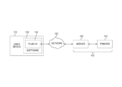
[0019] Figure 1B illustrates a block diagram of one embodiment of the
embedment
positioning tape forming system of the present disclosure.
[0020] Figure 1C illustrates a flowchart of one embodiment of the
method for
forming the embedment positioning tape of the present disclosure.
[0021] Figure 1D illustrates a flowchart of another embodiment of the
method for
forming the embedment positioning tape of the present disclosure.
[0022] Figure 2 illustrates perspective views of one embodiment of the
embedment
markers of the present disclosure.
[0023] Figure 3 illustrates perspective views of one embodiment of the
embedment
positioning system of the present disclosure.
[0024] Figure 4 illustrates perspective views of another embodiment of
the
embedment positioning system of the present disclosure.
DETAILED DESCRIPTION OF EXAMPLE EMBODIMENTS
- 6 -
CA 02894154 2015-06-05
WO 2014/089391 PCT/US2013/073483
[0025] Various embodiments of the present disclosure provide an
embedment
positioning system that facilitates the positioning of one or more embedments
along an edge of a
concrete form.
Embedment Positioning Tape
[0026] Turning now to the Figures and particularly to Figure 1A, in
one embodiment,
the present disclosure provides an embedment positioning tape, which is
generally indicated by
numeral 20. The embedment positioning tape is housed within a housing or cover
30. The
embedment positioning tape 20 is formed (such as by printing) with embedment
position
indicators indicating the positions at which a plurality of different
embedments (such as
embedment 50) are to be positioned along a concrete form (such as concrete
form 70). The
embedment positioning tape 20 is also formed (such as by printing) with a
control line location
indicator that indicates the location of a control line.
[0027] In operation, a user (such as a worker) unrolls the embedment
positioning tape
20 and attaches the embedment positioning tape 20 along an edge of the
concrete form 70 such
that the control line location indicator lines up with the actual control line
provided by the
general contractor. This enables the user to ensure that the embedment
positioning tape is
accurately positioned on the edge of the concrete form. Once the embedment
positioning tape is
attached to the edge of the concrete form, the user uses the embedment
positioning indicators to
easily position the embedments at the correct positions along the edge of the
concrete form
without having to hand-measure those positions for each individual embedment.
Additionally,
the user may use the embedment positioning tape to verify whether the
embedments are in the
correct positions along the concrete form edge both before and after the
concrete is poured.
[0028] It should be appreciated that the embedment positioning tape
may be attached
to the edge of the concrete form in any suitable manner, such as via staples,
adhesive, or
magnets. It should also be appreciated that the embedment positioning tape may
be formed
offsite and delivered to the jobsite on an as-needed basis or that the
embedment positioning tape
may be formed on the jobsite. It should further be appreciated that the
embedment positioning
tape is made of a durable, non-stretch, and weatherproof material.
[0029] The embedment positioning tape of the present disclosure solves
certain of the
above-described problems. The embedment positioning tape highlights precisely
where the
- 7 -
CA 02894154 2015-06-05
WO 2014/089391 PCT/US2013/073483
embedments are to be positioned along the edge of the concrete form, which
eliminates the need
for a user to use a tape measure to hand-measure the positions of the
embedments and, therefore,
eliminates the potential for human error in those measurements. The embedment
positioning
tape thus eliminates the time required to make such measurements as well as
the associated labor
costs. Further, the embedment positioning tape enables users to quickly and
easily verify
whether the embedments are in the correct positions along the edge of the
concrete form before
and after the concrete is poured.
[0030] Various embodiments of the present disclosure provide a system
and method
for forming the embedment positioning tape. Figure 1B illustrates a block
diagram of one
embodiment of the embedment positioning tape forming system 100. In this
illustrated
embodiment, the embedment positioning tape forming system 100 includes: (a) at
least one
central server, central controller, or remote host 130, which includes one or
more central
processing units and one or more memory devices (as described in detail
below); and (b) at least
one embedment positioning tape printer 140. In this illustrated embodiment, as
described in
detail below, the server 130 is configured to communicate over a network 120
with a plug-in 104
of a software program 102 installed on a user device 110. It should be
appreciated that the user
device may be any suitable computing device, such as (but not limited to) a
desktop computer, a
laptop computer, a tablet computer, a personal digital assistant (PDA), and a
cell phone (such as
a smartphone).
[0031] Figure 1C illustrates a flowchart of an example process or
method 200 of
operating the embedment positioning tape forming system 100. In various
embodiments, the
process 200 is represented by a set of instructions stored in one or more
memories and executed
by one or more processors. Although the process 200 is described with
reference to the
flowchart shown in Figure 1C, it should be appreciated that many other
processes of performing
the acts associated with this illustrated process may be employed. For
example, the order of
certain of the illustrated blocks may be changed, certain of the illustrated
blocks may be optional,
and/or certain of the illustrated blocks may not be employed.
[0032] In operation of this embodiment, a user of the user device 110
executes the
software program 102 to create one or more architectural drawings, such as
shop drawings,
indicating (among other features) the positions of one or more embedments
along a concrete
form, and saves the one or more architectural drawings as one or more
electronic architectural
- 8 -
CA 02894154 2015-06-05
WO 2014/089391 PCT/US2013/073483
drawing files on the user device 110. Thereafter, the software plug-in 104
extracts embedment
positioning information associated with the positions of the one or more
embedments along the
concrete form from the electronic architectural drawing files, and creates a
data file representing
the embedment positioning information. The user device 110 sends the data file
to the server
130 over the network 120. As indicated by block 210, the server 130 receives
the data file from
the user device 110. The server 130 processes the received data file and
determines, for each of
the one or more embedments, a desired position of that embedment along the
concrete form, as
indicated by block 220. The server 130 causes the embedment positioning tape
printer 140 to
print the desired positions of the one or more embedments along the concrete
form on an
embedment positioning tape, as indicated by block 230. The embedment
positioning tape is then
sent or otherwise provided to the user.
[0033] In various embodiments, instead of (or in addition to)
employing the software
plug-in, the embedment positioning tape forming system is configured to
maintain and provide a
website that is accessible by the user via the user device. The website
includes a system user
interface (system UI) that enables the user to, after accessing the website
using the user device,
use the embedment positioning tape forming system to cause the embedment
positioning tape to
be formed. In other embodiments, the embedment positioning tape forming system
employs one
or more applications (commonly referred to as "apps") downloaded to the user's
user device. In
one example, the user opens or launches an application on the user's tablet
computing device or
smartphone (i.e., the user's user device), and the application provides the
user access to the
system UI (which may be the same as the system UI provided on the website or a
modified
system UI optimized for mobile use). Thus, in these embodiments, the user is
not required to
navigate to any website to access the system UI and cause the embedment
positioning tape to be
formed. In one embodiment, the embedment positioning tape forming system
enables a user to
purchase a "premium" or "upgraded" application that includes additional
features or
functionality.
[0034] Figure 1D illustrates a flowchart of an example process or
method 300 of
operating this embodiment of the embedment positioning tape forming system. In
various
embodiments, the process 300 is represented by a set of instructions stored in
one or more
memories and executed by one or more processors. Although the process 300 is
described with
reference to the flowchart shown in Figure 1D, it should be appreciated that
many other
- 9 -
CA 02894154 2015-06-05
WO 2014/089391 PCT/US2013/073483
processes of performing the acts associated with this illustrated process may
be employed. For
example, the order of certain of the illustrated blocks may be changed,
certain of the illustrated
blocks may be optional, and/or certain of the illustrated blocks may not be
employed.
[0035] In operation of this embodiment, the user of the user device
executes the
software to create one or more architectural drawings indicating the positions
of one or more
embedments along a concrete form and saves the one or more architectural
drawings as one or
more electronic architectural drawing files on the user device. Thereafter,
the website or
application enables the user to upload the electronic architectural drawing
file(s) directly to the
server over the network. As illustrated in block 310, after receiving the
uploaded electronic
architectural drawing file(s), the server extracts embedment positioning
information from the
electronic architectural drawing file(s). The embedment positioning
information associated with
the positions of the one or more embedments along the concrete form. Using the
extracted
embedment positioning information, the server determines, for each of the one
or more
embedments, a desired position of that embedment along a concrete form, as
indicated by block
320. The server causes the embedment positioning tape printer to print the
desired positions of
the one or more embedments along the concrete form on an embedment positioning
tape, as
indicated by block 330. The embedment positioning tape is then sent or
otherwise provided to
the user.
[0036] In certain embodiments, the one or more electronic
architectural drawing files
include information in addition to the embedment positioning information that
the embedment
positioning tape forming system may extract and cause the embedment
positioning tape printer
to print onto the embedment positioning tape, such as the position of one or
more control lines
along the concrete form, the name of the jobsite, and the location of the
jobsite.
[0037] The present disclosure contemplates a variety of different
systems each having
one or more of a plurality of different features, attributes, or
characteristics. It should be
appreciated that a system as used herein refers to various configurations of:
(a) one or more
central servers, central controllers, or remote hosts; and/or (b) one or more
embedment
positioning tape printers. For brevity and clarity, unless specifically stated
otherwise, "central
server, central controller, or remote host" as used herein represents one
central server, central
controller, or remote host or a plurality of central servers, central
controllers, or remote hosts.
- 10 -
CA 02894154 2015-06-05
WO 2014/089391 PCT/US2013/073483
[0038] The central server, central controller, or remote host is any
suitable computing
device (such as a server) that includes at least one processor and at least
one memory device or
storage device. The user device includes at least one user device processor
configured to
transmit and receive data or signals representing events, messages, commands,
or any other
suitable information between the user device and the central server, central
controller, or remote
host. The at least one processor of that user device is configured to execute
the events,
messages, or commands represented by such data or signals in conjunction with
the operation of
the user device. Moreover, the at least one processor of the central server,
central controller, or
remote host is configured to transmit and receive data or signals representing
events, messages,
commands, or any other suitable information between the central server,
central controller, or
remote host and the user device. The at least one processor of the central
server, central
controller, or remote host is configured to execute the events, messages, or
commands
represented by such data or signals in conjunction with the operation of the
central server, central
controller, or remote host. It should be appreciated that one, more, or each
of the functions of the
central server, central controller, or remote host may be performed by the at
least one processor
of the user device. It should be further appreciated that one, more, or each
of the functions of the
at least one processor of the user device may be performed by the at least one
processor of the
central server, central controller, or remote host.
[0039] It should be appreciated that, in various embodiments, the
network is any
suitable data network, such as the Internet, an intranet, an internet, a
mobile communications
network, a local area network (LAN), or a wide area network (WAN). It should
be appreciated
that the central server, central controller, or remote host and the user
device are configured to
connect to the data network or remote communications link in any suitable
manner. In various
embodiments, such a connection is accomplished via: a conventional phone line
or other data
transmission line, a digital subscriber line (DSL), a T-1 line, a coaxial
cable, a fiber optic cable, a
wireless or wired routing device, a mobile communications network connection
(such as a
cellular network or mobile intern& network), or any other suitable medium.
Embedment Markers
[0040] Turning now to Figure 2, in another embodiment, the present
disclosure
provides a plurality of embedment markers, which are generally indicated by
numerals 420. In
- 11 -
CA 02894154 2015-06-05
WO 2014/089391 PCT/US2013/073483
operation, one or more users attach the embedment markers 420 to embedments
450 either
before or after the embedments are attached to the concrete form such that
after those
embedments are attached to the concrete form, the embedment markers act as
visual indicators of
the positions of the embedments. This enables the users to quickly and easily
verify the total
number of embedments as well as the positions of those embedments along the
edge of the
concrete form.
[0041] In one embodiment, the embedment markers include magnetic bases
that
enable the embedment markers to be easily attached to and detached from the
embedments.
Such embedment markers are readily reusable.
[0042] In certain embodiments, each embedment marker includes a level
sensor. In
one such embodiment, each embedment marker is configured to emit an audible
signal if the
embedment to which the embedment marker is attached is out of level by more
than a designated
amount. In another such embodiment, each embedment marker is configured to
emit a lighted
signal (e.g., a flashing light) if the embedment to which the embedment marker
is attached is out
of level by more than a designated amount. Thus, in these embodiments, the
embedment
markers enable users to quickly and easily verify whether the embedments are
sufficiently level
as well as to verify the total number of embedments and the positions of those
embedments along
the edge of the concrete form.
[0043] In other embodiments, each embedment marker includes a
transmitter
configured to communicate embedment position information representing a
position of that
embedment marker (and, therefore, the position of the embedment attached
thereto) to a receiver
unit. The receiver unit stores or is configured to access a master embedment
layout including the
desired position of each embedment, and is configured to compare the received
embedment
position information with the master embedment layout to verify that each
embedment is
positioned correctly according to the master embedment layout. The receiver
unit may also
verify that the total number of embedments is equal to the total number of
embedments included
in the master embedment layout. In one such embodiment, each embedment marker
is also
configured to communicate to the receiver unit embedment level information
representing
whether the embedment to which the embedment marker is attached is
sufficiently level.
[0044] The embedment markers of the present disclosure solve certain
of the above-
described problems. The embedment markers enable users to easily verify
whether the
- 12 -
CA 02894154 2015-06-05
WO 2014/089391 PCT/US2013/073483
embedments are in the correct positions along the edge of the concrete form
both before and after
the concrete is poured. The embedment markers thus eliminate the time required
to make such
determinations as well as the associated labor costs. Further, in certain
embodiments, the
embedment markers automatically alert users when the embedments to which they
are attached
are not sufficiently level, which eliminates the time required to manually
make such
determinations as well as the associated labor costs.
Embedment Positioning System
[0045] Turning now to Figure 3, in another embodiment, the present
disclosure
provides an embedment positioning system, which is generally indicated by
numeral 500. The
embedment positioning system 500 includes a base transmitter unit 510, a
receiver 520, and a
plurality of embedments 550 each including one or more targets 530. In
operation, a user brings
an embedment 550 to the general position at which the embedment 550 is to be
positioned along
the edge of the concrete form. The base transmitter unit 510 sends a signal
(such as a laser
signal) to the embedment 550 as the user moves the embedment 550 along the
edge of the
concrete form. The user moves the embedment 550 along the edge of the concrete
form until the
target 530 on the embedment 550 lights up, glows, or otherwise provides an
indication. When
the target 530 on the embedment 550 provides this indication, the user
attaches the embedment
550 to the concrete form. The indication thus notifies the user that the
embedment is at the
correct position along the edge of the concrete form.
[0046] Once the embedment attached to the concrete form, the user
actuates a
"confirm," "next," or other suitable button on the receiver 520, which may be
a handheld
receiver, a personal digital assistant (PDA), a smartphone, a tablet computing
device, a laptop
computing device, or any other suitable device. This indicates to the base
transmitter unit 520
that the user is ready to position the next embedment (if any). The user then
brings another
embedment to the general position at which the embedment is to be positioned
along the edge of
the concrete form and repeats this process.
[0047] In certain embodiments, the base transmitter unit includes a
camera
configured to periodically take pictures of the positions of the anchored
embedments. The base
transmitter unit then compares the positions of the anchored embedments shown
in the pictures
to a master embedment layout that includes the desired position of each
embedment. This
- 13 -
CA 02894154 2015-06-05
WO 2014/089391 PCT/US2013/073483
enables the base unit to perform periodic checks to verify that the embedments
have been
correctly positioned. In one embodiment, the base unit stores data
representing the positions of
the embedments.
[0048] Figure 4 illustrates another embodiment of the embedment
positioning system.
In operation of this embodiment, a user positions an embedment positioning
receiver 570 at the
center of an embedment 550. The base transmitter unit 510 communicates the
desired position
of the embedment 550 along the edge of the concrete form to the embedment
positioning
receiver 570. The embedment positioning receiver 570 displays, emits, or
otherwise indicates
directional signals that indicate where the user should position the embedment
550. Thus, in this
embodiment, the embedment positioning system provides real-time directional
signals to the user
to aid the user in positioning the embedment.
[0049] The embedment positioning system of the present disclosure
solves certain of
the above-described problems. The embedment positioning system highlights
precisely where
the embedments are to be positioned along the edge of the concrete form and
eliminates the need
for users to use a tape measure to hand-measure the positions of the
embedments and, therefore,
eliminates the potential for human error in those measurements. The embedment
positioning
system thus eliminates the time required to make such measurements as well as
the associated
labor costs. Further, the embedment positioning system enables users to easily
verify whether
the embedments are in the correct positions along the edge of the concrete
form before and after
the concrete is poured. Additionally, the embedment positioning system
eliminates the time and
labor required to manually make such determinations as well as the costs
associated with this
labor.
[0050] It should be understood that various changes and modifications
to the
presently preferred embodiments described herein will be apparent to those
skilled in the art.
Such changes and modifications can be made without departing from the spirit
and scope of the
present subject matter and without diminishing its intended advantages. It is
therefore intended
that such changes and modifications be covered by the appended claims.
- 14 -