Note: Descriptions are shown in the official language in which they were submitted.
CA 02894179 2015-06-11
BLOWDOWN STREAM FILTRATION TECHNIQUES FOR STEAM GENERATION IN
THERMAL IN SITU HYDROCARBON RECOVERY OPERATIONS
TECHNICAL FIELD
[001] The technical field generally relates to thermal in situ hydrocarbon
recovery
operations and more particularly to filtration of blowdown streams to be
reused for steam
generation in such operations.
BACKGROUND
[002] Thermal in situ bitumen or heavy hydrocarbon recovery operations can use
high
temperature steam for injection into a hydrocarbon-bearing reservoir. Steam
injection
heats the hydrocarbons, reducing the viscosity and increasing the mobility to
facilitate
production. Production fluids that are recovered from the reservoir are
separated into
produced hydrocarbons and produced water. The produced water is subjected to
water
treatment so that at least some of the water can be reused.
[003] Thermal in situ hydrocarbon recovery operations, such as Steam-Assisted
Gravity Drainage (SAGD), therefore include generating steam for such injection
into the
hydrocarbon-bearing reservoir. The produced water is treated to remove
contaminants
and provide treated water for use as feed water in a steam generator, such as
a drum
boiler or Once-Through Steam Generator (OTSG). Some steam generators, such as
OTSGs, produce wet steam that is separated into saturated steam and a blowdown
stream. The blowdown stream includes various contaminants, such as dissolved
organic
compounds and inorganic compounds including calcium, magnesium, silica and
various
dissolved salts. A portion of the blowdown stream can be recycled back to
water
treatment, such as a warm lime softener (WLS) or evaporators, and the rest of
the
blowdown stream is disposed of, which can involve significant costs.
[004] Contaminants in the produced water and blowdown streams are relevant to
numerous problems related to steam generation, water treatment and disposal
operations, such as fouling on equipment surfaces. Treatment of such blowdown
streams and reuse of water present in such blowdown stream in steam generation
involve various challenges, which may include accumulation of different
impurities in the
process, fouling of equipment, and energy consumption.
1
CA 02894179 2015-06-11
SUMMARY OF INVENTION
[005] Various techniques are provided for generating steam for a thermal in
situ
hydrocarbon recovery operation, in which a blowdown stream is subjected to
filtration
prior to reuse as feed water supplied to a steam generator.
[006] In one aspect, there is provided a system for in situ recovery of
hydrocarbons
including bitumen and/or heavy oil from a geological formation. The system
includes:
a Steam-Assisted Gravity Drainage (SAGD) well pair, including an injection
well
and a production well, wherein the injection well receives steam for injection
into
the geological formation so as to produce a production fluid via the
production
well;
a hydrocarbon-water separator for receiving the production fluid and producing
a
hydrocarbon-enriched stream and a produced water stream;
a water treatment unit for receiving the produced water stream and producing
treated water;
a boiler feed water tank configured to receive at least a portion of the
treated
water and provide feed water;
a Once-Through Steam Generator (OTSG) in fluid communication with the boiler
feed water tank, the OTSG receiving the feed water from the boiler feed water
tank, and producing the steam and a blowdown stream including dissolved
organic compounds, divalent cations and monovalent cations;
a nano-filtration unit in fluid communication with the OTSG to receive a
portion of
the blowdown stream, wherein the nano-filtration unit includes:
an inlet for receiving the portion of the blowdown stream as a filter feed
stream;
at least one filtration device including a membrane to remove a
substantial portion of the dissolved organic compounds and divalent
cations from the filter feed stream, thereby producing a filtered blowdown
stream and a concentrate including the dissolved organic compounds and
divalent cations; and
2
CA 2894179 2017-04-25
an outlet for expelling the filtered blowdown stream; and
a recycle line in fluid communication with the outlet of the filtration unit
and the
boiler feed water tank, to recycle the filtered blowdown stream from the
filtration
unit directly to the boiler feed water tank as a portion of the feed water.
[007] In another aspect, there is provided a system for generating steam for
use in a
steam-dependent process. The system includes:
a Once-Through Steam Generator (OTSG) producing steam and a blowdown
stream from feed water;
a filtration unit in fluid communication with the OTSG to receive at least a
portion
of the blowdown stream, wherein the filtration unit includes:
at least one filtration device including at least one membrane to remove
targeted contaminants from the at least a portion of the blowdown stream,
thereby producing a filtered blowdown stream and a concentrate including
the targeted contaminants; and
a recycle line in fluid communication with the filtration unit to recycle the
filtered
blowdown stream from the filtration unit as a portion of the feed water
upstream to
the OTSG without any further water treatment.
[007a] More particularly, there is provided a system for generating steam for
use in a
steam-dependent process, the system including:
a Once-Through Steam Generator (OTSG) producing steam and a blowdown
stream from feed water;
a filtration unit in fluid communication with the OTSG to receive at least a
portion
of the blowdown stream, wherein the filtration unit comprises:
at least one filtration device including at least one nano-filtration membrane
to
remove targeted contaminants from the at least a portion of the blowdown
stream,
the targeted contaminants comprising dissolved organic matter and polyvalent
inorganic ions, thereby producing a filtered blowdown stream and a concentrate
comprising the targeted contaminants; and
3
=
CA 2894179 2017-04-25
=
a recycle line in fluid communication with the filtration unit to recycle the
filtered
blowdown stream from the filtration unit as a portion of the feed water
upstream to
the OTSG without any further water treatment.
[008] In some implementations, the targeted contaminants may include dissolved
organic matter.
[009] In some implementations, the at least one filtration device may include
a nano-
filtration membrane configured to selectively retain dissolved organic matter
and
polyvalent inorganic ions including calcium, magnesium and silica.
[010] In some implementations, the nano-filtration membrane may have a
molecular
weight cut off (MWCO) between 200 and 3000 Da.
[011] In some implementations, pores of the nano-filtration membrane may have
a pore
size between about 0.001 pm and about 0.01 pm.
[012] In some implementations, the nano-filtration membrane may include a
softening
membrane.
3a
CA 02894179 2015-06-11
[013] In some implementations, the targeted contaminants removed by the
softening
membrane may include the polyvalent inorganic ions including calcium,
magnesium and
silica.
[014] In some implementations, the nano-filtration membrane may include a
desalination membrane.
[015] In some implementations, the targeted contaminants removed by the
desalination
membrane may include monovalent inorganic ions including sodium and chloride.
[016] In some implementations, the system may further include a bypass line in
fluid
communication with the OTSG and the recycle line, the bypass line being
configured to
bypass a part of the blowdown stream around the filtration unit as an
unfiltered
blowdown stream and add the unfiltered blowdown stream to the filtered
blowdown
stream.
[017] In some implementations, the system may further include a mixing unit to
combine the filtered blowdown stream and the unfiltered blowdown stream in
given
proportions before recycling through the recycle line as the portion of the
feed water.
[018] In some implementations, the filtration unit may include a series of
filtration
devices in fluid communication with one another so as to feed the concentrate
from an n-
stage filtration device to an (n+1)-stage filtration device, the filtered
blowdown stream
from the n-stage filtration device being recycled as feed water through the
recycle line.
[019] In some implementations, the filtration unit may include a first
assembly of
filtration devices and a second assembly of filtration devices, the first
assembly and the
second assembly being arranged in series and the filtration devices of a same
assembly
being arranged in parallel to one another, the concentrate from each
filtration device of
the first assembly being fed to the second assembly.
[020] In some implementations, the first assembly of filtration devices may
include at
least four filtration devices arranged in parallel, and wherein the second
assembly of
filtration devices may include at least two filtration devices arranged in
parallel.
In some implementations, each of the at least one filtration device may
include multiple
membrane elements, the membranes from each membrane element being arranged in
parallel in relation to each other and the membrane elements being arranged in
series
4
CA 02894179 2015-06-11
so as to feed the permeate of a first membrane element to a subsequent
membrane
element.
[021] In some implementations, the pore size of the membrane from the n-stage
filtration device may be different from the pore size of the membrane of the
(n+1)-stage
filtration device.
[022] In some implementations, the recycle line may be configured to directly
recycle
the filtered blowdown stream as feed water to the OTSG.
[023] In some implementations, the system may further include a feed water
tank in
fluid communication with the OTSG and the recycle line, the filtered blowdown
stream
being directly recycled to the feed water tank via the recycle line.
[024] In some implementations, part of the feed water may be derived from a
water
treatment unit for treating of produced water from a thermal in situ
hydrocarbon recovery
operation.
[025] In some implementations, the blowdown stream may have a pH of at least
4.
Optionally, the blowdown stream may have a pH between about 4 and 12.5.
[026] In some implementations, the at least one membrane may have a MWCO
between about 650 Da and 800 Da and may produce a filtered blowdown stream
with an
initial permeate flux between 15 and 70 GFD, at a temperature between 20 C and
80 C,
and under a constant pressure between 100 psi and 270 psi, the filtered
blowdown
stream having a dissolved organic content rejection of at least about 80% and
a total
dissolved solids rejection of at least about 40%.
[027] In some implementations, the system may include a pre-treatment unit in
fluid
communication with the filtration unit, the pre-treatment unit being
configured to prepare
the blowdown stream for filtration by modifying at least one of:
a temperature of the blowdown stream;
a pH of the blowdown stream; and
a concentration or size of suspended solids in the blowdown stream.
[028] In some implementations, the pre-treatment unit may include an
acidification
device to maintain the blowdown stream at a pH between about 4 and 12.5.
CA 02894179 2015-06-11
[029] In some implementations, the pre-treatment unit may include a
coagulation
device for adding coagulant to the blowdown stream, upstream of the filtration
unit.
[030] In another aspect, there is provided a method for in situ recovery of
hydrocarbons
from a geological formation using a Steam-Assisted Gravity Drainage (SAGD)
operation.
The method includes:
injecting steam via an injection well of a SAGD well pair to mobilize
hydrocarbons
in the geological formation;
recovering a production fluid including mobilized hydrocarbons from a SAGD
production well;
separating the production fluid into a hydrocarbon-enriched stream and a
produced water stream;
subjecting the produced water stream to water treatment to produce a treated
water;
supplying the treated water as feed water to a once-through steam generator
(OTSG) to produce steam and a blowdown stream;
nano-filtering at least a portion of the blowdown stream to remove a
substantial
portion of dissolved organic compounds and divalent cations from the blowdown
stream, thereby producing a filtered blowdown stream and a concentrate
including the dissolved organic compounds and divalent cations; and
recycling the filtered blowdown stream back to the OTSG without any further
water treatment for use as a portion of the feed water for steam generation.
[031] In another aspect, there is provided a method for generating steam in a
steam-
dependent process. The method includes:
operating a Once-Through Steam Generator (OTSG) to produce steam and a
blowdown stream from feed water;
filtering at least a portion of the blowdown stream to remove targeted
contaminants and produce a filtered blowdown stream and a concentrate
including the targeted contaminants; and
6
CA 2894179 2017-04-25
recycling the filtered blowdown stream upstream to the OTSG without any
further
water treatment for use as a portion of the feed water for steam generation.
[031a] More particularly, there is provided a method for generating steam in a
steam-
dependent process, the method including:
operating a Once-Through Steam Generator (OTSG) to produce steam and a
blowdown stream from feed water;
nano-filtering at least a portion of the blowdown stream by at least one nano-
filtration membrane configured to selectively retain targeted contaminants
from the
blowdown stream, the targeted contaminants comprising dissolved organic matter
and polyvalent inorganic ions, thereby producing a filtered blowdown stream
and
a concentrate comprising the targeted contaminants; and
recycling the filtered blowdown stream upstream to the OTSG without any
further
water treatment for use as a portion of the feed water for steam generation.
[032] In some implementations, the method may further include supplying the
filtered
blowdown stream directly from the filtering as the feed water.
[033] In some implementations, the filtering may include nano-filtering the at
least a
portion of the blowdown stream by a nano-filtration membrane configured to
selectively
retain dissolved organic matter and polyvalent inorganic ions including
calcium,
magnesium and silica.
[034] In some implementations, the nano-filtration membrane may have a
molecular
weight cut off (MWCO) between 200 and 3000 Da.
[035] In some implementations, pores of the nano-filtration membrane may have
a pore
size between 0.001 pm and 0.01 pm.
[036] In some implementations, the nano-filtration membrane may include a
softening
membrane.
[037] In some implementations, the targeted contaminants removed by the
softening
membrane may include the polyvalent inorganic ions including calcium,
magnesium and
silica.
7
CA 2894179 2017-04-25
[038] In some implementations, the nano-filtration membrane may include a
desalination
membrane.
[039] In some implementations, the targeted contaminants removed by the
desalination
membrane may include monovalent inorganic ions including sodium and chloride.
[040] In some implementations, the method may further include:
bypassing a bypass portion of the blowdown stream from filtering, to produce
an
unfiltered blowdown stream; and
adding at least part of the unfiltered blowdown stream to the filtered
blowdown
stream.
[041] In some implementations, the method may further include combining the
filtered
blowdown stream and the unfiltered blowdown stream in given proportions before
recycling as the portion of the feed water.
7a
CA 02894179 2015-06-11
[042] In some implementations, the filtering may be performed as a staged
filtration by
using the concentrate from an n-stage filtration step as feed for an (n+1)-
stage filtration
step, the filtered blowdown stream from each n-stage filtration step being
recycled as
feed water.
[043] In some implementations, filtration operating conditions of the n-stage
filtration
step may be different from filtration operating conditions of the (n+1)-stage
filtration step.
[044] In some implementations, the blowdown stream may have a pH of at least
4.
[045] In some implementations, the method may further include nano-filtering
the at
least a portion of the blowdown stream with at least one membrane having a
MWCO
between 650 Da and 800 Da, and applying a constant pressure between 100 psi
and
270 psi during nano-filtering of the blowdown stream having pH between 4 and
12.5 and
temperature between 20 C and 80 C to obtain an initial permeate flux between
15 and
70 GFD of the filtered blowdown stream with a dissolved organic content
rejection of at
least about 80% and a total dissolved solids rejection of at least about 40%.
[046] In some implementations, the method may include adjusting the pH of the
blowdown stream between about 4 and 12.
[047] In some implementations, the method may further include adjusting the pH
of the
blowdown stream to between about 4 and 8 to enhance precipitation of highly
charged
contaminants from the blowdown stream and deposition of the highly charged
contaminants as a gel-like foulant layer on the at least one membrane.
[048] In some implementations, the method may include providing the pH of the
blowdown stream so as to promote sustained permeate flux.
[049] In some implementations, the pH of the blowdown stream may be adjusted
so as
to sustain the permeate flux for a filtration time of at least 60 minutes.
[050] In some implementations, the permeate flux may be sustained at at least
about
15 GFD.
[051] In some implementations, the method may further include maintaining the
constant permeate flux of the filtered blowdown stream between 40 GFD and 120
GFD
and sustaining the dissolved organic content rejection at at least about 80%
and the total
dissolved solids rejection at at least about 40% for a filtration time of at
least 60 minutes.
8
[052] In some implementations, the method may further include maintaining the
constant
pressure between about 120 psi and 180 psi to sustain stable permeate flux
between 30
GFD and 50 GFD for a filtration time of at least 60 minutes.
[053] In some implementations, the method may further include supplying the
blowdown
stream directly from the OTSG for filtering.
[054] In some implementations, the method may include pre-treating the
blowdown
stream, before filtering, by modifying at least one of:
a temperature of the blowdown stream;
a pH of the blowdown stream; and
a concentration or size of suspended solids in the blowdown stream.
[055] In some implementations, the pre-treating may include acidifying the
blowdown
stream to adjust the pH to between about 4 and 12.5.
[056] In some implementations, the pre-treating may include acidifying the
blowdown
stream to adjust the pH to between about 8 and 10.
[057] In some implementations, the pre-treating may include adding a coagulant
to the
blowdown stream.
[058] In some implementations, the coagulant may be aluminum-based and the
aluminum content may be between 200 ppm and 400 ppm.
[058a] In another aspect, there is provided a system for generating steam for
use in a
steam-dependent process, the system comprising:
a boiler producing steam and a blowdown stream from feed water;
a filtration unit in fluid communication with the boiler to receive at least a
portion of
the blowdown stream, wherein the filtration unit comprises:
at least one filtration device including at least one filtration membrane
having a
molecular weight cut off between 100 and 3000 Da, to remove targeted
contaminants from the at least a portion of the blowdown stream, the targeted
contaminants comprising dissolved organic matter, polyvalent inorganic ions
and/or monovalent inorganic ions, thereby producing a filtered blowdown stream
and a concentrate comprising the targeted contaminants; and
9
CA 2894179 2018-07-18
a recycle line in fluid communication with the filtration unit to recycle the
filtered
blowdown stream from the filtration unit as a portion of the feed water
upstream to
the boiler.
[058b] In another aspect, there is provideda method for generating steam in a
steam-
dependent process, the method comprising:
operating a boiler to produce steam and a blowdown stream from feed water;
filtering at least a portion of the blowdown stream by at least one filtration
membrane having a molecular weight cut off between 100 and 3000 Da and
configured to selectively retain targeted contaminants from the blowdown
stream,
the targeted contaminants comprising dissolved organic matter and polyvalent
inorganic ions, thereby producing a filtered blowdown stream and a concentrate
comprising the targeted contaminants; and
recycling the filtered blowdown stream upstream to the boiler for use as a
portion
of the feed water for steam generation.
[068c] In another aspect, there is provided a system for generating steam for
use in a
steam-dependent process, the system comprising:
a boiler producing steam and a blowdown stream from feed water;
a filtration unit in fluid communication with the boiler to receive at least a
portion of
the blowdown stream, wherein the filtration unit comprises:
a first filtration device including a first filtration membrane to remove a
first
targeted contaminant from the at least a portion of the blowdown stream,
the first targeted contaminant comprising dissolved organic matter, thereby
producing a permeate and a concentrate comprising the first targeted
contaminant, and
a second filtration device to receive at least a portion of the permeate, the
second filtration device including a second filtration membrane to remove a
second targeted contaminant from the at least a portion of the permeate,
the second targeted contaminant comprising monovalent and/or polyvalent
inorganic ions, and the second filtration membrane having a pore size
smaller than the first filtration membrane, thereby producing a filtered
9a
CA 2894179 2018-07-18
blowdown stream and another concentrate comprising the second targeted
contaminant; and
a recycle line in fluid communication with the filtration unit to recycle the
filtered
blowdown stream from the filtration unit as a portion of the feed water
upstream to
the boiler.
[058d] In another aspect, there is provided a method for generating steam in a
steam-
dependent process, the method comprising:
operating a boiler to produce steam and a blowdown stream from feed water;
filtering at least a portion of the blowdown stream by a first filtration
membrane
configured to selectively retain a first targeted contaminant from the
blowdown
stream, the first targeted contaminant comprising dissolved organic matter
thereby
producing a permeate and a concentrate comprising the first targeted
contaminant;
filtering at least a portion of the permeate by a second filtration membrane
configured to selectively retain a second targeted contaminant from the
permeate,
the second targeted contaminant comprising polyvalent and/or monovalent
inorganic ions, and the second filtration membrane having a pore size smaller
than
the first filtration membrane, thereby producing a filtered blowdown stream
and
another concentrate comprising the second targeted contaminant; and
recycling the filtered blowdown stream upstream to the boiler for use as a
portion
of the feed water for steam generation.
[059] It should also be noted that various features of the processes and
systems
described above and herein may be combined with other features and aspects of
the
processes and systems.
BRIEF SUMMARY OF DRAWINGS
[060] Fig 1 is a flow diagram of a steam generation system including a
blowdown filtration
unit.
[061] Hg 2 is another flow diagram of a steam generation system including a
blowdown
filtration unit.
[062] Fig 3 is another flow diagram of a steam generation system including a
blowdown
filtration unit.
9b
CA 2894179 2018-05-22
CA 02894179 2015-06-11
[063] Fig 4 is another flow diagram of a steam generation system including a
blowdown
filtration unit.
[064] Fig 5 is a diagram of a filtration device including a plurality of
filtration
membranes.
[065] Fig 6 is a flow diagram of a system for in-situ recovery of
hydrocarbons.
[066] Fig 7 is a graph of removal of dissolved organic compounds (c)/0) versus
aluminum dosage from coagulant addition (ppm) in blowdown stream at initial
pH=4, 8
and 11.9 for two different coagulants (generic aluminum sulfate and commercial
PAX-
18).
[067] Fig 8 is a graph of removal of hydrophobic acid (%) versus aluminum
dosage
from coagulant addition (ppm) in blowdown stream at initial pH=4, 8 and 11.9
for two
different coagulants (generic aluminum sulfate and commercial PA)(-18).
[068] Fig 9 is a graph of pH after coagulation versus aluminum dosage from
coagulant
addition (ppm) in blowdown stream at initial pH=4, 8 and 11.9 for two
different
coagulants (generic aluminum sulfate and commercial PA)(-18).
[069] Fig 10 is a graph of flux (%) versus filtration time of a blowdown
stream of
unadjusted pH=11.9, of pH=8 and of pH=4.
[070] Fig 11 is a graph of contaminant rejection (%) versus filtration time
(min).
[071] Fig 12 is a graph of flux (GFD) versus filtration time (min).
[072] Fig. 13 is a graph of contaminant rejection (%) versus recovery (%).
[073] Fig. 14 is a graph of permeate flux (GFD) versus recovery (%).
DETAILED DESCRIPTION
[074] As part of a thermal in situ hydrocarbon recovery operation, a blowdown
stream
from a steam generator can be subjected to filtration to remove contaminants
and the
resulting filtered blowdown stream can be recycled back as part of the feed
water of the
steam generator. Filtration of blowdown streams, such as Once-Through Steam
Generator (OTSG) blowdown, can help respond to the water needs of a steam-
dependent process, such as Steam-Assisted Gravity Drainage (SAGD). OTSG
blowdown streams can be supplied directly to filtration for removal of
contaminants, such
as dissolved organic compounds and divalent cations, and at least part of the
filtered
CA 02894179 2015-06-11
blowdown stream can be directly supplied as feed water to the OTSG, thus
avoiding
both additional water treatment steps before and after filtration as well as
recycling the
blowdown back into the produced water treatment units. The blowdown filtration
can
provide a number of advantages, such as reusing water in steam generation in
an
efficient manner and reducing fouling concerns due to contaminants in the
blowdown,
while avoiding numerous water treatment steps and the addition of the blowdown
to the
produced water for water treatment.
[075] In some implementations, physical treatment of the blowdown stream by
membrane filtration is performed to produce suitable feed water for steam
generation,
which includes at least one OTSG. Various aspects and implementations
regarding
filtration of the blowdown stream will be discussed further below.
[076] Figs 1 to 5 show different steam generation system implementations
including
units for filtering a blowdown stream from an OTSG and recycling the filtered
blowdown
stream as feed water for the OTSG. Fig 6 shows an implementation of the steam
generation system, as shown in Figs 1 to 5, as part of a SAGD system. These
figures
will be discussed and referred to in greater detail further below.
[077] In some implementations, the steam generation system includes a steam
generator which produces steam and a blowdown stream from feed water. It
should be
noted that steam generators such as OTSGs generate a wet steam stream that is
separated into a dry saturated steam stream and a blowdown stream, and that
this
separation step can be considered to be part of the steam generator. The
blowdown
stream contains various contaminants including dissolved organic and inorganic
matter,
monovalent ions, polyvalent ions and suspended solids. In order to remove at
least part
of these contaminants from the blowdown stream, the system also includes a
filtration
unit in fluid communication with the steam generator to receive the blowdown
stream for
filtration thereof.
[078] It should be understood that the steam generator can include any
apparatus for
generating steam with a steam quality suitable for use in various
applications. The steam
generator may include an OTSG or another boiler that generates a blowdown
stream
having contaminants concentrations suited for treatment by filtration. The
OTSG can be
part of a Heat-Recovery Steam Generation (HRSG) system, where hot exhaust gas
derived from an electricity generation process, and potentially further heated
using
additional duct firing, is used in the OTSG to heat the boiler feed water.
11
CA 02894179 2015-06-11
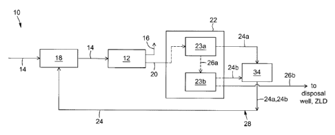
[079] Fig 1 shows an example of a steam generation system 10 including a
boiler 12
receiving feed water 14 for generating steam 16. The boiler 12 is in fluid
communication
with a feed water tank 18 in which the feed water is stored for further use by
the boiler
12. The boiler 12 also generates a blowdown stream 20 including contaminants
that are
present in the feed water 14. For OTSGs, approximately 10 to 30 wt% of the
feed water
becomes blowdown and there is thus approximately a three- to ten-fold
concentration of
the contaminants in the blowdown stream.
[080] In some implementations, a portion of the feed water is derived from
produced
water from thermal in situ hydrocarbon recovery operations. Some of the
contaminants
contained in the produced water can therefore be found in the feed water and
are further
concentrated in the blowdown stream exiting the steam generator, as noted
above.
Direct recycling of the blowdown stream would thus lead to accumulation of
contaminants in the steam generation process as well as increased risk of
fouling and
inefficiencies in equipment operation. More regarding the contaminants of the
blowdown
stream is discussed further below.
Blowdown stream contaminants
[081] In some implementations, the blowdown stream may contain contaminants
including Dissolved Organic Matter (DOM), dissolved inorganic matter such as
silica,
monovalent ions and polyvalent ions.
[082] Typically, blowdown streams from thermal in situ hydrocarbon recovery
operations have a high content of DOM. The DOM concentration build-up in the
blowdown stream can be due to a lack of DOM-specific removal steps in
conventional
produced water treatment operations. Furthermore, the high pH present in some
conventional produced water treatment processes (e.g., evaporation) can
enhance the
solubility of the organic matter in the water.
[083] In addition, OTSG blowdown streams from thermal in situ hydrocarbon
recovery
operations often include monovalent ions including sodium and chloride ions,
and
polyvalent ions including barium, calcium, iron, magnesium. Such ions are
dissolved and
also have different properties that have an impact in terms of removal,
detection and
problems within the steam generation system.
12
CA 02894179 2015-06-11
Filtration implementations
[084] Referring to Fig 1, the steam generation system 10 includes a filtration
unit 22 for
removing targeted contaminants from the blowdown stream 20. At least a portion
of the
blowdown stream 20 is sent to the filtration unit 22 to produce a filtered
blowdown
stream 24 (also referred to as permeate) and a concentrate 26 including the
targeted
contaminants. The filtration unit 22 can be in fluid communication with the
feed water
tank 18 so as to recycle the filtered blowdown stream 24 as a portion of the
feed water
14 via a recycle line 28. The rest of the blowdown stream 20 can be sent to
disposal,
which may include a zero liquid discharge (ZLD) system.
[085] In some implementations, the filtration unit 22 can include at least one
filtration
device and each filtration device can include at least one membrane having
characteristics tailored for removal of one or more of the targeted
contaminants that can
include DOM, monovalent ions and/or polyvalent ions.
[086] In some implementations, at least one of the membranes of a given
filtration
device may be a nano-filtration membrane. The filtration device including one
or more
nano-filtration membranes may be referred to as a nano-filtration device.
Optionally, the
nano-filtration membrane characteristics can include a Molecular Weight Cut
Off
(MWCO) between about 100 and 3000 Da and an average pore size between about
0.001 pm and about 0.01 pm. It should be noted that the MWCO refers to the
lowest
molecular weight solute in which 90% of the solute is retained by the
membrane. The
membrane performance can be evaluated by monitoring the flux decline or the
rejection
of certain targeted contaminants. As will be further detailed below, the
membrane
performance can be influenced by various factors including pH, temperature,
and the
nature of contaminants. A nano-filtration membrane can offer a filtration
performance
suited for an OTSG blowdown stream used in a SAGD operation, as nano-
filtration
membranes have been found to tolerate high pH, high temperatures, be
reasonably
tolerant of organic matter, and provide effective removal of the contaminants
that lead to
decreased performance of OTSGs without requiring treatment of the blowdown
before or
after nano-filtration. Nano-filtration membranes that are oleophobic or
strongly
hydrophilic can be advantageous for nano-filtration of OTSG blowdown. Nano-
filtration
membranes that can operate at elevated pH and temperature are advantageous for
nano-filtration of OTSG blowdown.
13
CA 02894179 2015-06-11
[087] In some implementations, at least one membrane of the filtration device
may be
made from polymeric material or ceramic material.
[088] In some implementations, depending on the average pore size range of the
membrane, the nano-filtration membrane may be a softening membrane, a
desalination
membrane or a combination thereof. For example, a softening membrane can be
used
to remove polyvalent ions, such as calcium and magnesium, from the blowdown
stream
and allow monovalent ions to pass through. In other implementations, a
desalination
membrane can be used to remove monovalent ions as well.
[089] The use of the above-mentioned filtration treatment in a steam-dependent
process can enable a feed water quality tailored for steam generation without
having to
perform any further water treatment of the blowdown stream. In some scenarios,
part of
the blowdown can be directly supplied to the filtration unit, and the filtered
blowdown can
be supplied directly to the boiler feed water tank, and thus the only
equipment involved
other than the filtration unit would be the piping, instrumentation, valves,
and possibly
pumps required to displace the stream. The filtered blowdown stream may be
directly
recycled as feed water for generation of steam, i.e., without any physical
and/or
chemical treatment. In the case of thermal in situ recovery operations such as
SAGD,
filtering the blowdown stream without any pre-treatment or further water
treatment
enables lower equipment and chemical costs as well as not diminishing the
produced
water treatment capacity.
[090] In some other scenarios, there may be other units that are provided
before and/or
after the filtration unit. For example, the filtered blowdown stream may be
heated by a
heat exchanger before recycling upstream to the steam generator, and/or the
blowdown
stream may be cooled prior to supplying to the filtration unit. Other units
can be provided
to make minor adjustments to the chemistry and/or operating conditions of the
blowdown
or filtered blowdown, while still avoiding significant water treatment
interventions.
[091] It should be noted that the one or more filtration devices may be
adapted to
perform dead-end filtration and/or cross-flow filtration. Optionally, the
filtration device can
include at least one membrane that may be configured for dead-end filtration
where the
blowdown stream flows through the membrane due to a difference in pressure,
the
contaminants being retained in the concentrate and the filtered blowdown
stream being
released at the other end. Optionally, the filtration device can include at
least one
membrane that may be configured for cross-flow filtration where the blowdown
stream
14
CA 02894179 2015-06-11
flows tangentially across the surface of the membrane, such tangential flow
aiding in
washing away contaminants that may potentially accumulate on the membrane
surface.
[092] It should be further noted that membrane characteristics, such as pore
size,
material, configuration, etc., can be modified according to various factors,
such as the
process operating conditions, the nature of the blowdown contaminants, and/or
geographical and seasonal variations in water quality within the system. Such
adaptability of the membranes may provide enhancements in terms of operation
at
considerably higher temperatures, ability to back flush, and cleaning
capabilities to
improve membrane performance and lifetime while minimizing steam generation
system
downtime.
Filtration by-pass implementations
[093] In some implementations, a portion of the blowdown stream can be
bypassed
around the filtration unit as an unfiltered portion. The filtered portion of
the blowdown
stream can be mixed with the unfiltered portion, so as to create feed water
with an
acceptable concentration of targeted contaminants for steam generation. The
proportion
of bypassed versus filtered blowdown can be varied depending on the desired
contaminant levels for the feed water. There may therefore be one or more
measurement devices for measuring contaminant levels in the blowdown and/or in
the
feed water, and the bypassed proportion can be adjusted depending on the
measured
contaminant levels and the desired contaminant levels. This implementation can
enable,
for example, slowing down the flux decline of the membrane, since a lower
quantity of
contaminants would be filtered compared to sending all of the blowdown stream
into the
filtration unit.
[094] Referring to Fig 2, the steam generation system 10 can include a bypass
line 30
in fluid communication with the boiler 12 to bypass a portion of the blowdown
stream 20
around the filtration unit 22 as an unfiltered blowdown stream 32. The
filtered blowdown
stream 24 and the unfiltered blowdown stream 32 can be combined in given
proportions
before recycling through the recycle line 28 as the portion of the feed water
14.
[095] In some implementations, between 25% and 100% of the blowdown stream may
be supplied to the filtration unit, while the remaining portion of the
blowdown stream is
bypassed and can be mixed into the filtered blowdown or sent to disposal. The
amount
CA 02894179 2015-06-11
of unfiltered blowdown that is bypassed and mixed into the filtered blowdown
can be
selected depending on the filtration membrane characteristics and the desired
contaminant levels in the feed water, such that when a given membrane removes
more
contaminants than is required for recycling as feed water, adding the amount
of
unfiltered blowdown can enable additional water to be recycled while staying
below the
desired contaminant levels. The combined stream of filtered and unfiltered
blowdown
may be provided so as to have a DOM content reduction of at least 40% and a
TDS
content reduction of at least 10% compared to the initial untreated blowdown.
Optionally,
the TDS content reduction may be of 40% compared to the initial untreated
blowdown.
Multi-stage filtration implementations
[096] The filtration unit may include a plurality of filtration devices that
may be arranged
in series to perform staged filtration. For example, staged filtration may be
chosen to
enhance contaminant removal efficiency and/or increase contaminant
concentration in
the final concentrate. The staged filtration may be provided to selectively
remove at least
a first contaminant with a first filtration device and at least a second
contaminant with a
second filtration device, thereby limiting flux decline while reducing fouling
of
membranes of each of the filtration devices.
[097] In some implementations, the filtration unit includes a plurality of
filtration devices
in fluid communication with one another so as to feed the concentrate from an
n-stage
filtration device to an (n+1)-stage filtration device. The filtered blowdown
stream from the
n-stage filtration device may be recycled as feed water through the recycle
line. This
staged filtration configuration can increase overall water recovery from the
blowdown.
[098] In some implementations, the filtration unit can include a plurality of
filtration
devices, which can be arranged in series. Referring to Fig 3, the steam
generation
system includes a filtration unit 22 having two filtration devices 23a and
23b. Each
filtration device 23a, 23b may include one or more membranes (not shown in Fig
3) as
described above. The blowdown stream 24 from the OTSG boiler 12 is fed to the
first
filtration device 23a to remove targeted contaminants from the blowdown stream
24, and
to produce a first filtered blowdown stream 24a and a first concentrate 26a
containing
the targeted contaminants. The first concentrate 26a is then fed into the
second filtration
device 23b to produce a second filtered blowdown stream 24b and a second
concentrate
26b containing the targeted contaminants. The second concentrate 26b,
including the
16
CA 02894179 2015-06-11
contaminants from the first concentrate, can be sent to disposal, for example
a disposal
well or a ZLD system. The first filtered blowdown stream 24a and the second
filtered
blowdown stream 24b can be combined in a mixing unit 34 or simple pipe
connection
(e.g., Tee) so as to be recycled to the feed water tank 18 via the recycle
line 28 for
further use as feed water 14.
[099] In some implementations, a filtration unit can include a combination of
filtration
devices, some of which are arranged in series and other are arranged in
parallel. The
filtration devices which are arranged in parallel can be referred to as an
assembly (or
bank) of filtration devices. Referring to Fig 4, the steam generation system
includes a
filtration unit 22 having a first assembly A of filtration devices (filtration
stage 1) and a
second assembly B of filtration devices (filtration stage 2). The first and
second
assemblies A and B are arranged in series so as to feed a first concentrate
26A
containing the targeted contaminants from the first assembly A to the second
assembly
B. As illustrated, the first assembly A can include multiple (e.g., four)
filtration devices
23A arranged in parallel and the second assembly B can include multiple (e.g.,
two)
filtration devices 23B. First and second filtered blowdown streams 24A and 24B
from the
first and second assemblies A and B can be mixed as a filtered blowdown stream
24
which is fed to the feed water tank 18 via the recycle line 28 for further use
as feed water
14. The use of filtration devices arranged in parallel can increase the
overall membrane
filtration active area to treat the blowdown stream.
[100] Optionally, a filtration device can include a plurality of membranes to
obtain a
given membrane filtration surface area. The membranes can also be arranged in
series,
in parallel, or according to a combination thereof. In addition, the membranes
used in
each filtration device can be the same or can differ from one another
according to
surface area, average pore size, material, etc., if desired.
[101] In some implementations, the filtration device can include a plurality
of
membranes or membrane elements which are arranged inside a single pressure
vessel,
producing a permeate and a concentrate. Referring to Fig 5, the filtration
device 23
includes three membrane elements 35a, 35b, 35c arranged in series such that
the
concentrate of the first membrane element becomes the feed to the subsequent
membrane element, and so on. Each membrane element can include a spiral-wound
type membrane as illustrated in Fig 5. The permeate 24 from the first membrane
element 35a is sent to the second membrane element 35b via a conduit 58, which
may
17
CA 02894179 2015-06-11
include an 0-ring connector. The concentrate 26a from the first membrane
element 35a
is fed to the spiral wound membrane of the second membrane element 35b; and
the
concentrate 26b from the second membrane element 35b is fed to the spiral
wound
membrane of the third membrane element 35c. The concentrate 26c from the third
membrane element 35c is then evacuated separately via an appropriate conduit.
The
concentrates 26a, 26b, 26c from the membrane elements 35a, 35b, 35c
respectively are
isolated from one another with concentrate seals 60.
[102] In some implementations, the staged filtration may be tailored to the
quality
needed for the feed water. Optionally, the average pore size of the membranes
of the n-
stage filtration device may be different from the average pore size of the
membranes of
the (n+1)-stage filtration device. Further optionally, each filtration device
may include a
softening membrane to remove polyvalent ions, including calcium, magnesium and
silica, and a desalination membrane to remove monovalent ions (also referred
to as
salts) including sodium and chloride ions.
[103] It should be understood that the staged filtration implementation is not
limited to
the above mentioned configurations where the concentrates are serially
filtered. In one
implementation, the filtration unit can include a first filtration device
including a first
membrane for removing a first target contaminant, and a second filtration
device
configured to receive the permeate of the first filtration device and
including a second
membrane for removing a second target contaminant that is smaller than the
first target
contaminant, thereby producing a permeate from which both contaminants have
been
substantially removed. For example, the first membrane can be a softening
membrane
for removing divalent cations and DOM, and the second membrane can be a
desalination membrane for removing monovalent cations. By targeting different
contaminants in different filtration devices, the overall water quality can be
increased
while not incurring substantial build-up on the membranes with smaller pore
sizes. In
another implementation, the filtration unit can include a plurality of
filtration devices
arranged in series, each filtration device including for example a plurality
of membranes
arranged in a single pressure vessel so as to define a membrane module. In
another
implementation, the filtration unit can include a plurality of filtration
devices (or
membrane modules) arranged in parallel so as to perform filtration of various
portions of
the blowdown stream, permeate, concentrate or a combination thereof. It should
be
noted that the filtration unit may include combined configurations of
filtration devices in
18
CA 02894179 2015-06-11
series and in parallel to tailor the filtration treatment to the feed water
quality
requirements. The plurality of filtration devices may also be arranged as a
bank of
devices where the filtration devices are configured in parallel with one
another.
SAGD implementations
[104] Fig 6 schematically illustrates an example of a SAGD thermal in situ
hydrocarbon
recovery operation, which uses a well pair 36 within a reservoir 38 to recover
hydrocarbons. The well pair 36 includes an injection well 37 and an underlying
production well 38. The injection well 37 is employed to inject a mobilizing
fluid, such as
steam 16, into the reservoir 38 to mobilize the hydrocarbons. Other fluids can
be co-
injected with steam. Condensate and mobilized hydrocarbons are recovered via
the
production well 38 as production fluid 40. The production fluid 40 is supplied
to an oil-
water separator 42 to give a produced hydrocarbons stream 44 (e.g., produced
bitumen)
and produced water 46. Diluent 48 can be added to enhance the separation of
the oil
from the water, and in such scenarios the produced hydrocarbons stream 44 is
diluted
with diluent. The produced water 46 includes various organic and inorganic
contaminants, from the hydrocarbons and the minerals present in the reservoir.
Some of
the contaminants can lead to fouling of downstream equipment.
[105] Referring still to Fig 6, the produced water 46 is supplied to a water
treatment unit
50 for further chemical and/or physical treatment. At least part of the
contaminants from
the produced water 46 may be removed or processed in the water treatment unit
50. The
water treatment unit 50 may include various equipment, such as de-oilers,
evaporators,
lime softeners (e.g., warm or hot), cation exchangers (e.g., weak acid),
filters, etc., in
order to produce the treated water suitable for use as feed water in the steam
generator.
The treated produced water 52 is then supplied to the steam generation system
10. The
steam generation system 10 includes the boiler feed water tank 18 that can
receive the
treated produced water to form the feed water 14. The feed water 14 is fed to
at least
one OTSG 11 which may be part of a bank of several OTSGs in parallel. The OTSG
11
generates wet steam 54 including about 20% liquid and is supplied to a steam-
water
separator 13 that produces dry steam 16 and a blowdown stream 20. The dry
steam 16
is used, at least in part, as the steam injected into the reservoir 38. The
blowdown
stream 20, including contaminants from the produced water 46, is fed to a
filtration unit,
such as a nano-filtration unit 22 including at least one membrane to remove at
least
19
CA 02894179 2015-06-11
DOM and polyvalent ions. Optionally, the nano-filtration unit 22 may also be
configured
to remove monovalent ions. The nano-filtration unit 22 produces a filtered
blowdown
stream 24 which can be directly recycled by the recycle line 28 to the boiler
feed water
tank 18 without any further water treatment.
[106] In some implementations, the nano-filtration step of the blowdown stream
from
SAGD operations can enable a DOM rejection rate between 40% and 90%,
optionally of
85%, and a Total Dissolved Solids (TDS) rejection rate between 10% and 50%,
optionally of 40%.
[107] It should be noted that implementations of the method and system can
include
pre-treating the blowdown stream with coagulation and/or acidification pre-
treatment,
which may be adapted at least in part based on the experimental data discussed
herein.
Other implementations can include no chemical pre-treatment of the blowdown or
possibly selecting operating conditions at which coagulation and acidification
pre-
treatment have minimal or no effect on subsequent filtration performance.
[108] It should be also understood that filtration operating conditions
include at least
membrane pore size, TDS rejection, DOM rejection, pH of the blowdown stream,
temperature and pressure of the blowdown stream and permeate flux (of the
filtered
blowdown stream).
EXPERIMENTATION & EXAMPLES
[109] The following section relates to experiments and examples that help
illustrate
possible implementations and/or advantages of the systems and processes
described
herein. Figs 7 to 14 are based on experimental data derived from a series of
blowdown
filtration experiments evaluating membrane performance (with or without
acidification
and/or coagulation pre-treatment of the blowdown) and identifying filtration
parameters,
as described below.
[110] Acidification and coagulation tests were performed on blowdown stream
samples
to evaluate impact of performing a pre-treatment step and to select a
potential coagulant
suited for an enhanced pre-treatment step prior to membrane filtration.
[111] Filtration tests were performed with dead-end membrane filtration and
cross-flow
membrane filtration to test and enhance the membrane performance for treating
an
CA 02894179 2015-06-11
OTSG blowdown stream used in a SAGD operation for recovering bitumen from an
oil
sands reservoir.
[112] Dead-end filtration tests were performed at room temperature using a
stainless
steel pressure vessel (Sterlitech, HP475011"). The vessel was pressurized
using high
purity nitrogen gas and constant stirring was maintained using a suspended
magnetic
stir bar operated at 700 rpm. Dead-end filtration was used for preliminary
flux decline
tests.
[113] Cross-flow filtration tests were performed using a flat-sheet cross flow
cell
(Sterlitech SEPA Cell TM) operated at 70 C with a constant cross flow rate
maintained at
1 GPM, which corresponded to a Reynolds number of 3500. Two sets of cross flow
filtration tests were performed:
1) recirculation mode for 1 hour with complete return of all permeate to the
feed
tank to observe the effect of initial flux on membrane performance; and
2) bleed mode with the permeate removed from the system to observe the effect
of product water recovery on membrane performance.
[114] All tests were operated at constant pressure to observe flux decline and
rejection
of Dissolved Organic Carbon (DOC) and conductivity.
Characterization of the blowdown stream samples
[115] Experiments were performed on aliquots of blowdown streams to
characterize
Total Dissolved Solids (TDS), Total Suspended Solids (TSS), Total Organic
Carbon
(TOC), Dissolved Organic Carbon (DOC) and specific ions concentrations.
Conductivity,
pH, temperature and scaling potential were also measured. Characterization of
the
blowdown stream facilitated for an efficient selection of coagulant candidates
and
membrane candidates for bench testing. The commercial nano-filtration membrane
series chosen for the tests can be continuously operated at temperatures and
pH of up
to 70 C and 13.5, respectively. The series contains three commercially
available
membranes that span a Molecular Weight Cut Off (MWCO) between 720 Da and 3000
Da.
21
CA 02894179 2015-06-11
Experimental series 1: Coagulation treatment tests
[116] A series of coagulation tests was performed to study the effect of
coagulant type,
dose, and initial pH on DOG removal from the blowdown stream samples at
elevated
temperature. The commercial polyaluminum chloride (PA)(l8TM, from Kemira) was
compared to generic aluminum sulfate with coagulant dose selected to maintain
an
identical concentration of dissolved aluminum (see Table 1).
[117] A multi-holder heating shaker was used to perform six coagulation tests
simultaneously at a temperature of 85 C to match an expected boiler blowdown
stream
temperature in the field. The coagulation protocol involved an initial fast
mixing at 1000
rpm for one minute followed by a slow mixing at 200 rpm for 20 minutes. All
samples
were then allowed to cool and settle overnight before any analytical
measurements were
made.
[118] Experimental analyses included measuring final solution pH, turbidity,
and
conductivity as well as supernatant DOC, specific UV absorbance (SUVA), color,
and
hydrophobic acid content. It should be noted that hydrophobic acid (HoA)
content was
measured by measuring the change in DOG after acidification to pH 2.
Table 1
Test # Coagulant Coagulant Aluminum Total [AI3]
Initial pH
dose (mg/L) content by
weight (%)
1 11.9
2 8
3 4
4 Al2(SO4)3 269 15.8 42.5 11.9
Al2(SO4)3 269 15.8 42.5 8
6 Al2(SO4)3 269 15.8 42.5 4
7 Al2(SO4)3 538 15.8 85 11.9
8 Al2(SO4)3 538 15.8 85 8
22
CA 02894179 2015-06-11
9 Al2(SO4)3 538 15.8 85 4
Al2(S043 2692 15.8 425 11.9
11 Al2(SO4)3 2692 15.8 425 8
12 Al2(SO4)3 2692 15.8 425 4
13 PAX-18 TM 500 8.5 42.5 11.9
14 PAX-18 TM 500 8.5 42.5 8
_
PAX-18 TM 500 8.5 42.5 4
16 PAX-181M 1000 8.5 85 11.9
17 PAX-18 TM 1000 8.5 85 8
18 PAX-18 TM 1000 8.5 85 4
19 PAX-18 TM 5000 8.5 425 11.9
PAX-18 TM 5000 8.5 425 8
21 PAX-18 TM 5000 8.5 425 4
[119] Results of the coagulation tests performed on the samples from Table 1
are
shown in graphic form in Figs 7 to 9.
[120] Referring to Figs 7 and 8, when organic removal was maximized (i.e., at
high
coagulant doses), the behavior of p1jç18TM and generic aluminum sulfate were
essentially identical. Removal of 43% of DOG and 98% of HoA was maximized with
an
excessive aluminum dose of 425 ppm. However, in comparison to pre-
acidification, it
should be noted that DOC and HoA removal was only marginally lower (28% and
91%,
respectively) just by acidification down to pH 4 without any coagulant added.
[121] Referring to Fig 9, initial pH has proven to be a factor which greatly
affects the
extent of organic precipitation and removal. The effect of coagulant addition
can be
mostly explained when considering the coagulant as an acid to promote the
spontaneous precipitation of hydrophobic acids. Fig 9 shows the effect of
coagulant
addition on solution pH with both p18TM and generic aluminum sulfate
coagulants,
behaving identically as effective acidifiers. Ineffective removal at an
initial pH of 11.9 was
23
CA 02894179 2015-06-11
primarily due to the inefficiency of the coagulant to reduce pH. Even when pH
was
lowered to 9 at an aluminum dose of 425 mg/L, which is within the optimum pH
range for
PAX18TM, removal only marginally improved to about 5% and about 20% for DOC
and
HoA, respectively. As initial pH was lowered, the alkalinity of the blowdown
stream
sample was reduced and it became easier for the coagulant to further reduce
pH, which
resulted in improved organic removal primarily by direct precipitation of HoA.
Experimental series 2: Dead-end filtration at room temperature
[122] Bench-scale dead-end filtration tests were performed to study the effect
of in-line
coagulation and initial pH on rejection of targeted contaminants (also
referred to as
solutes) from the blowdown stream sample as well as membrane performance
stability.
The chosen membrane HydraCoRe70pHTTm has a MWCO of 720 Da with an observed
rejection of about 85% for TOC and about 40% for TDS at room temperature as
reported
in Table 2 for a blowdown stream of unadjusted pH 11.9. Filtration resulted in
significant
color removal from the blowdown stream samples.
Table 2
Conductivity
Sample pH DOC
rejection (Y0)
rejection (%)
Blowdown stream 11.9
(filter feed)
Blowdown stream
12.0 39.9 84.9
permeate
blowdown stream +
1000 ppm PAX-18 11.6
TM filter feed
blowdown stream +
1000 ppm PAX-18 11.6 47.6 85.1
TM permeate
blowdown stream
8.0
filter feed (pH=8)
blowdown stream 7.7 62.5 88
permeate (pH=8)
blowdown stream 4.0
filter feed (pH=4)
blowdown stream 4.5 70.5 45.1
permeate (pH=4)
24
CA 02894179 2015-06-11
[123] According to Table 2, DOC rejection was relatively unaffected by in-line
coagulation with 1000 ppm of pj8TM or acidification to pH 8, and was
substantially
lowered when with acidification to pH 4.
[124] As seen during the coagulation tests, acidification and coagulation pre-
treatment
did not result in significant removal of dissolved organics by the membrane.
Results from
Table 2 indicate that, at initial pH=4, the non-precipitated dissolved
organics remaining
in the acidified blowdown stream were less effectively removed by nano-
filtration,
resulting in almost half the observed DOG rejection for unadjusted blowdown
stream.
The opposite effect was observed with respect to salt passage in that
conductivity
rejection increased at lower pH.
[125] These observations can be explained by the effect of pH on electrostatic
membrane-solute interactions. Increased passage of dissolved organics at low
pH is
most likely due to protonation of acidic organic functional groups, resulting
in charge
neutralization and hindered electrostatic repulsion by the charged membrane
surface.
However, salt rejection increased as pH decreased, which was due to the
precipitation
and deposition of a highly charged gel-like foulant layer on the membrane
surface. This
foulant layer increased rejection of salt ions by electrostatic forces
because, unlike
dissolved organic matter, salt ions possess strong point charges which are
unaffected by
pH.
[126] Effect of pre-treatment by coagulation and/or acidification on flux
decline was
also studied, with results reported in Fig 10. Unadjusted blowdown had one of
the best
performances when analyzing flux decline during the dead-end filtration tests.
The most
significant flux decline was observed during the filtration of blowdown stream
samples at
pH 4. Almost 40% flux loss was observed within the first 10 minutes at which
flux
stabilized at around 10 GFD. Visual examination of the membrane after
filtration
revealed that the observed flux loss was due to significant deposition of
precipitated
organics on the membrane surface.
[127] Still referring to Fig 10, in-line coagulation with 1000 ppm of pAX18TM
resulted in
a more gradual and slower rate of flux decline (almost 20% flux after 60
minutes). Flux
decline by in-line coagulation was also attributed to surface fouling of
precipitated
material, but visual examination of the membrane revealed that there was less
precipitate formed during in-line coagulation and that acidification to pH 4
was
characterized by a significantly denser and more gelatinous foulant.
CA 02894179 2015-06-11
Still referring to Fig 10, the most sustainable flux was achieved with the BBD
either
unadjusted with a natural pH of 11.9 or acidified to pH 8. Filtration of
blowdown stream
sample having an unadjusted pH of 11.9 appeared to be the most economical and
sustainable option because it required the lowest applied pressure (150 psi)
to reach an
initial target flux of 16 GFD as seen in Table 3 (which was similar to the 165
psi pressure
required during in-line coagulation with 1000 ppm of p18TM coagulant). As
intrinsic
membrane pure water permeability was unchanged between pH 4 and pH 8, the
additional rise in applied pressure may be due to added resistance by the
gelatinous
foulant layer deposited on the membrane surface.
Table 3
NF Membrane pure water
pH permeability (22 C) Applied pressure during
(GFD/psi) filtration treatment (psi)
11.9 0.291 150
8.0 0.202 260
4.0 0.204 350
Experimental series 3: Cross flow filtration at elevated temperature
[128] Cross flow filtration tests were performed at 70 C in order to determine
optimal
operational settings (e.g., flux and recovery) under field-like conditions.
[129] A first set of cross flow experiments was performed in batch,
recirculation mode
to test the effect of applied pressure (initial flux) on solute rejection and
performance
stability. A high cross flow of 1 GPM was maintained to establish a high
shear, turbulent
mixing regime in the channel with a target Reynolds number of 3500. Constant
applied
pressures of 70, 150, and 230 psi were targeted, which resulted in initial
fluxes of 35, 44,
and 100 GFD.
[130] Fig 11 illustrates DOC and TDS rejection during nano-filtration of a
boiler
blowdown sample of unadjusted pH using a membrane having a Molecular Weight
Cut
Off (MWCO) of 720 Da in cross flow, permeate recirculation mode at 70 C and
with (a)
35 GFD initial flux at constant pressure of 70 psi, (b) 44 GFD initial flux at
constant
pressure of 150 psi, and (c) 100 GFD initial flux at constant pressure of 230
psi. Results
26
CA 02894179 2015-06-11
indicate that the intermediate operation at 150 psi led to the best permeate
quality.
There was not a significant difference in rejection when operated at 44 or 100
GFD initial
flux in which DOC and TDS rejection were relatively stable at 80% and 45%,
respectively, for the full duration of the tests. In addition, these results
suggest that the
solubility or molecular conformation of the DOM was not strongly affected by
temperature, which is affirmed by the similar DOC rejection between cross flow
filtration
at 70 C and the dead-end filtration performed at room temperature discussed
above.
[131] Fig 12 illustrates flux decline during the filtration of a boiler
blowdown sample of
unadjusted pH using a membrane having a MWCO of 720 Da in cross flow, permeate
recirculation mode at 70 C and with (a) 35 GFD initial flux at constant
pressure of 70
psi, (b) 44 GFD initial flux at constant pressure of 150 psi, and (c) 100 GFD
initial flux at
constant pressure of 230 psi. Operation at 44 GFD was determined to be the
most
optimal amongst those tested because it was shown to have the most stable
performance and was least affected by surface fouling. Although operation at
all tested
initial fluxes was relatively sustainable and stable throughout all the tests,
membrane
quality was the best when operated at an applied pressure of 150 psi and
initial flux of
44 GFD.
[132] A second set of cross flow experiments was performed as a "crash-out"
test in
which permeate was removed from the system in order to continually concentrate
the
boiler blowdown feed to determine the limiting recovery at which the membrane
failed.
The test was performed with an applied pressure of 150 psi because it was
shown to
have the most sustainable combination of minimal surface fouling and maximum
DOC
and TDS rejection (optimal performance with respect to flux stability and
solute
rejection).
[133] Fig 13 illustrates the effect of recovery on DOC and TDS rejection
during the
filtration of a boiler blowdown sample of unadjusted pH using a membrane
having a
MWCO of 720 Da in cross flow mode at a constant pressure of 150 psi and a
temperature of 70 C. Referring to Fig 13, stable permeate quality was achieved
up to
approximately 70% recovery. Rejection began to slightly drop to final values
of about
70% for DOC removal and about 30% for TDS removal, at 85% recovery.
[134] Fig 14 illustrates the effect of recovery on permeate flux during the
filtration of a
boiler blowdown sample of unadjusted pH using a membrane having a MWCO of 720
Da in cross flow mode at a constant pressure of 150 psi and a temperature of
70 C.
27
CA 02894179 2015-06-11
[135] Referring to Figs 13 and 14, although permeate quality was maintained
relatively
well with a loss in rejection from 10% to 15% at recovery up to 85%, flux
decline suffered
more heavily. Minimal flux decline was observed with recovery up to 60%.
However, flux
dropped significantly at recoveries greater than 60% with final flux loss of
about 75% at a
recovery of 85%. The majority of flux decline was due to increased solution
resistance
by the build-up of osmotic pressure as opposed to membrane fouling and cake
formation.
[136] Bench-scale studies from experimental series 1 and 2 show that direct
nano-
filtration of chemically unadjusted boiler blowdown stream at its original pH
provides
good performance with respect to solute rejection and flux stability.
Experimental series
3 further suggest that an exemplary target operating pressure of 150 psi with
an initial
flux of approximately 44 GFD can produce high quality permeate without
significant
membrane fouling.
Experimental series 4: Scale-up modeling and pilot-level design
[137] A preliminary design for a pilot-scale nano-filtration system was
created based on
results and recommendations from empirical bench studies as well as membrane
manufacturer information and modeling tools. The objective of this preliminary
design
was to develop and assess the configuration of the pilot system.
[138] A two-stage configuration as generally illustrated in Fig 4 was modeled.
Each of
the first and second stages includes a bank of filtration devices which are
arranged in
parallel. Each filtration device includes a pressure vessel containing three
membrane
elements in series, as seen on Fig 5. According to Table 4, two configurations
were
tested based on different operational specifications for a total feed
throughput of 30
GPM and recovery of 70%;
1) optimal flux determined from above bench tests of 44 GFD (75 LMH); and
2) conservative flux of 15 GFD (26 LMH) recommended by the membrane
manufacturer.
28
CA 02894179 2015-06-11
Table 4
Filtration device
(vessel) Membranes
Total
Design configuration per vessel /
membrane SEC (kWh/m3)
scenario Total
area (m2)
(Stage 1: Stage membranes
2)
Option I 2 : 1 6 / 18 117 0.51
Option II 6: 3 6 / 54 351 0.28
[139] Feed pressures of 150 psi and 75 psi were assumed for options I and II
respectively, with an average pressure drop of 15 psi estimated across each
stage. To
achieve at least 70% recovery, a two-stage plant is suggested to obtain
permeate TOG
below 1000 ppm for example.
[140] Although observations made in this experimental studies suggest that a
system
designed around a permeate flux of 44 GFD is the more optimal design, it is
important to
note that several long-term performance parameters were not studied such as
long-term
membrane performance stability, clean-in-place flux recovery, etc. The current
two-stage
design achieves a given target permeate quality, however, more elaborate
designs can
be considered (e.g., multiple permeate passes) to achieve higher purity
permeate if
desired.
[141] In addition, in some implementations, concentrate management may include
other options aside from direct disposal (e.g. zero liquid discharge system).
29