Note: Descriptions are shown in the official language in which they were submitted.
CA 02894181 2015-06-11
MEDICAL LENS ASSEMBLIES AND STERILE DRAPES
WITH A LENS
ASSEMBLY
FIELD OF THE INVENTION
100011 The present invention relates generally to optical devices requiring
a sterile
field. More particularly, the present invention relates to medical lens
assemblies and sterile
drapes with one or more lens assemblies for maintaining a sterile field.
BACKGROUND
[0002] During a surgical operation, the surgical site and surrounding areas
must
remain sterile. A "surgical field" is an environmentally-controlled area in a
typical
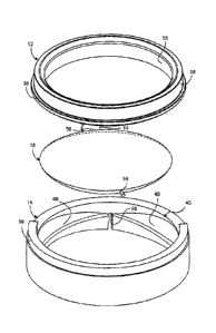
hospital operating room where the risk of infection, such as from naturally
occurring
organisms (e.g., bacteria), is minimized or eliminated. The sterility of the
surgical field is
typically controlled by limiting the introduction of infection-causing
bacteria and other
contaminants. In general, this is achieved by implementing strict regulations
over the
personnel and equipment present in the operating room.
[0003] Surgical drapes are often utilized during surgery in the operating
room to
minimize the risk of infection to surgical patients and to protect medical
equipment from the
surgical field. An array of different surgical drapes may be placed over the
patient and the
medical equipment to create a sterile barrier, preventing microorganisms and
other
contaminants that may cause infections from migrating to and from exposed
tissue, bodily
fluids, etc. For example, bodily fluids secreted during surgery that would
otherwise settle on
medical equipment, which would then become contaminated and potentially
hazardous, will
instead ultimately settle on the drapes and not on the draped medical
equipment.
[0004] Optical devices, such as surgical microscopes and cameras, have
become an
integral part of many operating rooms. Microscopes used for surgery are
generally
permanent fixtures of the operating room, typically mounted to the ceiling or
a wall, or
supported on a floor-mounted stand. Surgical microscopes often have an
articulated
cantilever support arrangement to facilitate movement of the microscope over
an operating
zone. Surgical microscopes normally take on very complex shapes, often having
several sets
1
CA 02894181 2015-06-11
of eyepieces that permit the surgeon and others to simultaneously view the
magnified area
under the microscope's objective lens. In addition to the ocular segments, one
or more
viewing tubes and/or laser arms (depending on design) project out from the
microscope
housing.
[0005] Due to its complex geometry, it is very time consuming and difficult
to
thoroughly sterilize an entire microscope assembly before and after each
surgical procedure.
As such, it is common practice to cover the microscope with a disposable
surgical drape.
The drape typically comprises a flexible sheet-form material that covers all
of the
components of the surgical microscope, including the ocular ports, the viewing
tubes, the
microscope head, and the structure that supports the head. The disposable
surgical drape is
typically manufactured and packaged under sterile conditions so that, when
unpackaged and
placed on a microscope, the drape creates a sterile field around the
microscope and its
components.
[0006] The microscope drape is often initially affixed to the microscope at
the lens
housing for the objective lens, to orient the drape with respect to other
structure of the
microscope. For example, some microscope drapes include an annular positioning
sleeve
that is attached to or integral with an elongated tubular cover. The
positioning sleeve fits
onto the objective lens housing of the microscope to initially affix the
sterile drape to the
microscope assembly. Once the surgical drape is attached to the objective lens
housing, the
remaining portions of the drape can be conveniently unfolded and positioned to
cover the
remainder of the microscope assembly.
[0007] In order to protect the objective lens without obstructing the view
of the
surgical area, a transparent protective lens (also referred to in the art as
"lens cover")
adapted to shield the objective lens is usually associated with the drape
assembly. For
example, in some prior art configurations, a housing comprising a rigid
mounting ring,
which encloses a transparent-plastic lens, is integrally-formed with the
drape. The mounting
ring housing is adapted to attach, typically via a separate adaptor or clamp,
to the outer
diameter of the microscope objective lens housing. Some designs incorporate an
interchangeable lens cover that can be removed from the lens cover housing and
replaced
with a substitute lens cover.
[0008] Unlike typical microscopes, the illuminating light source of many
surgical
microscopes comes from above and shines onto the lens cover covering the
objective lens,
2
CA 02894181 2015-06-11
which may generate glare when the surgeon looks through the microscope.
Moreover, during
surgical operations, the lens cover can be splattered by fluids from the
surgery, such as
blood, which will obscure the surgeon's vision. To rectify this problem,
someone on the
surgical team is conventionally required to either wipe the lens cover (which
can further
obscure the vision), remove and replace the lens cover (which requires a lens
cover be taken
from another drape assembly), or replace the entire drape (which temporarily
breaks the
sterile field, is time consuming, and wastes another entire drape assembly).
Finally,
different surgical microscopes use different size objective lenses. Thus, a
facility with a
variety of different surgical microscopes is required to carry an array of
different surgical
drape assemblies with lens housings and lens covers of various sizes,
increasing overhead
costs and unnecessarily complicating the preparation process for the operating
room.
SUMMARY OF THE INVENTION
10008a1 According to the present invention, there is also provided a drape
assembly for creating a barrier between a sterile field and an optical device
having an
objective lens, the drape assembly comprising:
a drape body comprising a flexible material sized to cover at least a
portion of the optical device;
a lens housing attached to the drape body and configured to engage with
the optical device to attach thereto proximate to the objective lens;
a lens cover holder removably attached to the lens housing to rotate about
a first axis; and
a lens cover mounted to the lens cover holder to pivot about a second axis
different from the first axis.
10008b1 According to the present invention, there is also provided a
surgical drape
assembly for creating a barrier between a sterile field of an operating room
and a surgical
microscope having at least one objective lens circumscribed by an annular
objective lens
housing, the surgical drape assembly comprising:
a drape body comprising a sheet-like material sized to cover at least a
portion of the surgical microscope;
3
CA 02894181 2015-06-11
an annular lens housing fixed to the drape body, the annular lens housing
being configured to circumscribe the objective lens housing and thereby
removably
attach the drape body to the surgical microscope;
an annular lens cover holder defining an internal chamber, the lens cover
holder being removably mounted to the annular lens housing to rotate about a
first axis
generally coaxial with a viewing axis of the objective lens; and
a substantially-transparent lens cover positioned inside and spanning
across the internal chamber of the lens cover holder, the lens cover being
hinged to the
lens cover holder to pivot about a second axis generally transverse with
respect to the
viewing axis of the objective lens.
[0008c] Preferably, according to the present invention, there is provided a
lens
assembly for a medical drape adapted to cover at least a portion of a medical
device with
an objective lens, the lens assembly comprising:
an annular lens housing attachable to the medical drape, the lens housing
being configured to engage with and thereby attach to the medical device;
an annular lens cover holder removably attachable to the annular lens
housing; the annular lens cover holder defining an internal chamber, and
a lens cover configured to shield the objective lens, the lens cover being
disposed within the internal chamber of the annular lens cover holder and
hinged to the
annular lens cover holder such that the lens cover is selectively pivotable
with respect to
the lens cover holder.
[0008d] Preferably, according to the present invention, there is also
provided a lens
assembly for a medical drape adapted to cover at least a portion of a medical
device
having an objective lens, the lens assembly comprising:
an annular lens housing attachable to the medical drape, the lens housing
being configured to engage with and thereby attach to the medical device;
an annular lens cover holder removably attachable to the annular lens
housing; and
a lens cover configured to shield the objective lens, the lens cover being
hinged to the annular lens cover holder such that the lens cover is
selectively pivotable
with respect to the lens cover holder,
wherein one of the annular lens housing and the annular lens cover holder
includes a flange protruding therefrom, and wherein the other of the annular
lens housing
4
CA 02894181 2015-06-11
and the annular lens cover holder includes a complementary arcuate slot
configured to
receive the flange and thereby attach the lens cover holder to the lens
housing.
BRIEF DESCRIPTION OF THE DRAWINGS
[0009] Various advantages of the invention will become apparent upon
reading
the following detailed description and upon reference to the drawings.
[0010] FIG. I is an exploded perspective-view illustration of a protective
lens
assembly in accordance with one embodiment of the present invention;
[0011] FIG. 2 is a cross-sectional side-view illustration of a sterile
drape
assembly in accordance with one embodiment of the present invention; and
[0012] FIG. 3 is a plan-view illustration of a lens cover holder in
accordance with
one embodiment of the present invention.
[0013] While the invention is susceptible to various modifications and
alternative
forms, specific embodiments are shown by way of example in the drawings and
will be
described in detail herein. It should be understood, however, that the
invention is not
intended to be limited to the particular forms disclosed. Rather, the
invention is to cover
all modifications, equivalents, and alternatives.
DESCRIPTION OF ILLUSTRATIVE EMBODIMENTS
[0014] While this invention is susceptible of embodiment in many different
forms, there is shown in the drawings and will herein be described in detail
representative embodiments of the invention with the understanding that the
present
disclosure is to be considered as an exemplification of the principles of the
invention and
is not intended to limit the broad aspect of the invention to the embodiments
illustrated.
To that extent, elements and limitations that are disclosed, for example, in
the Drawings,
Abstract, and Description of the Illustrative Embodiments section, but not
explicitly set
forth in the claims, should not be incorporated into the claims, singly or
collectively, by
implication, inference or otherwise.
[0015] The present invention will be described herein in the context of a
surgical
lens assembly and a sterile surgical drape assembly for covering a surgical
microscope
and creating a barrier between a sterile field of an operating room and a
surgical
microscope. However, the present invention is by no means limited to this
particular
application. By way of non-limiting example, the concepts of the present
invention may
CA 02894181 2015-06-11
just as easily be incorporated into sterile drape assemblies used in any
procedure
requiring a sterile field, including surgical procedures, non-surgical medical
procedures,
and non-medical operations (e.g., in a scientific research clean room).
Moreover, the lens
assemblies and drape assemblies of the present invention may be used on
surgical
microscopes and various other optical devices, such as medical imaging
equipment (e.g.,
surgical cameras), operating room light fixtures, etc. Finally, the drawings
presented
herein are not to scale and are provided purely for instructional purposes. As
such, absent
explicit claim language to the contrary, the individual and relative
dimensions and
orientations shown in the drawings are not to be considered limiting.
[0016] Referring to the drawings, wherein like reference numerals refer to
like
components throughout the several views, FIG. 1 provides an exploded
perspective-view
illustration of an exemplary medical lens assembly, designated generally as
10, in
accordance with various aspects of the present invention. The medical lens
assembly 10
includes three primary components: an annular lens housing 12, an annular lens
cover
holder 14, and a transparent, disc-shaped lens cover 16. Although depicted in
FIG. 1 as
circular, donut-shaped (i.e., toroidal) components, the lens housing 12 and
lens cover holder
14 may take on additional shapes (e.g., elliptical, polygonal, etc.),
individually or
collectively, depending on the intended application and design requirements of
the lens
assembly 10. Likewise, the lens cover 16 may take on additional geometric
configurations.
[0017] The lens housing 12 is attached or attachable to a surgical drape
20 to
form a drape assembly 18, as seen in FIG. 2. By way of example, the lens
housing 12
may be received in a complementary aperture 21 that is formed through a
portion of the
drape body 23. An adhesive may then be applied to the outer periphery of the
lens
housing 12 along the interface between the drape 20 and the lens housing 12,
whereby
the lens housing 12, and thus the entire lens assembly 10 of FIG. 2, is
coupled to the
drape 20. Alternatively, the lens housing 12 may be mechanically fastened to
(e.g., via
fasteners) or integrally formed with the drape body 23.
[0018] According to one intended application, the drape assembly 18 of
FIG. 2 may
be employed, as explained above, to create a physical barrier between a
sterile field of
an operating room and medical device, represented herein as a surgical
microscope
(shown hidden at 22 in FIG. 2). In general, the microscope 22 includes an
objective lens
24 that is circumscribed by, and generally encased within a cylindrical
objective lens
housing 26. The microscope 22 includes many other conventional components,
such as a
microscope body or main housing, one or more eyepieces, a light source, etc.
that are
6
CA 02894181 2015-06-11
well known in the art. Since these components are well known in the art, and
are per se
not part of the subject invention, these structures will not be discussed or
illustrated in
detail herein.
[0019] The lens housing 12 is configured to engage with and thereby attach
to the
medical device 22. In the illustrated embodiment, for example, the annular
lens housing 12
comprises an outer backing ring, designated as 28 in FIG. 1, with an inner-
diameter surface
30 comprised of a flexible material. According to one potential configuration,
the outer ring
28 is fabricated from a rigid polymer, such as polypropylene, with an
overmolded, soft
thermoplastic-elastomer (TPE) forming the inner-diameter surface 30.
Alternatively, other
materials can be used, such as polyethylene, ABS, or any thermal plastic. The
lens housing
12 may be axially pressed or fed onto the outer surface of the objective lens
housing 26 of
the surgical microscope 22. When circumscribing the objective lens 24, the
inner-diameter
surface 30 of the lens housing 12 compresses against and frictionally engages
the outer-
diameter surface of the objective lens housing 26, thereby attaching the drape
assembly 18,
including the lens assembly 10 and drape body 23, to the surgical microscope
22.
[0020] In the embodiment illustrated in FIG. 2, the lens housing 12 is
provided
with a ramped surface 32 that extends continuously around a forward inner-edge
thereof.
The ramped surface 32 acts as an angled alignment feature which facilitates
engagement
between the lens housing 12 and microscope 22 by properly orienting and
axially
aligning the lens housing 12 with the objective lens housing 26 when being
pressed
together. The lens assembly 10 may be removed from the microscope 22 by
pulling on or
otherwise disengaging the lens housing 12 from the objective lens housing 26.
It is also
envisioned that the lens assembly 10, namely lens housing 12, be operatively
coupled to
the microscope 22 by alternative means (e.g., via complementary helical
threads, snap-
fasteners, latches, adaptors, combinations thereof, etc.).
[0021] With continuing reference to FIG. 2, the inner-diameter surface 30
of the
annular lens housing 12 may include an optional plurality of compliant
protrusions 34 that
project radially inwardly therefrom. When the lens housing 12 is pressed onto
the
objective lens housing 26, the compliant protrusions 34 compress or squeeze
between the
inner-diameter surface 30 of the lens housing 12 and the outer-diameter
surface of the
objective lens housing 26, thereby increasing the frictional force between the
lens
housing 12 and objective lens housing 26. Three protrusions 34 are illustrated
in FIG. 2;
however, more or fewer than three protrusions 34 may be incorporated into the
lens
7
CA 02894181 2015-06-11
housing 12 design. This embodiment allows the inner-diameter surface 30 and
the outer
backing ring 28 to be molded and formed from the same material.
[0022] The surgical drape 20 is preferably made of materials now known or
hereinafter developed that are commonly used in medical drapes. Such materials
may
include, but are not limited to, coated papers and pretreated and/or pre-
impregnated
cloths, including non-woven and woven fabrics, such as spunbond polypropylene
(PPSB), spunlace, spunbond meltblown spunbond (SMS), and combinations thereof.
The drape material may also comprise bi-component non-woven materials, tri-
laminates,
bi-laminates, combinations thereof, and/or any variation of such fabrics. The
material
may include hydro-entangled materials and other fluid-resistant materials.
However, one
preferred material for the surgical drape 20 is a clear plastic, such as
polyethylene or
polyurethane, as the transparency eases application to the surgical microscope
22. It is
also possible for the plastic to be of a darker shade, while still being
transparent, in
order to reduce glare from the drape itself. An "eco drape" type material is
also
envisioned for the surgical drape 20, such as unbleached drape materials
and/or
fluorocarbon free drape materials that are biodegradable and/or compostable.
[0023] The size and shape of the drape body 23 is sufficient to cover at
least a
portion, but preferably all of the surgical microscope 22. The geometry and
dimensions of
the drape 20 may be varied depending upon factors such as the size and design
of the
microscope 22 and other practical considerations. It is generally desirable
that the drape
20 be provided with the appropriate extensions and necessary openings that
cover and/or
allow access to the various microscope oculars. The drape 20 may also include
optional
strips of cloth or plastic (not shown), which allow the drape body 23 to be
tightened and
secured to the microscope 22. For instance, plastic straps may be adhered or
otherwise
fixed at one end to an outer-side surface of the drape body 23, and provided
with adhesive
on the opposite end such that the user can wrap the straps around loose drape
material,
then secure the loose drape material to the microscope 22.
[0024] Referencing both FIGS. 1 and 2, the medical lens assembly 10
includes a
disposable and/or interchangeable lens cover holder 14, wherein the lens cover
holder
14 is easily attachable to and, in some embodiments, detachable from the lens
housing
12. According to one exemplary configuration, the lens housing 12 includes a
circular
flange 36 that protrudes radially outwardly from a bottom edge of the lens
housing 12.
In the illustrated embodiment, the flange 36 extends continuously around the
outer
perimeter of the annular lens housing 12. Alternatively, the circular flange
36 may be
8
CA 02894181 2015-06-11
broken down into a plurality of individual segments, each of which projects
radially
outwardly from the lens housing 12.
[0025] Continuing with the above example, the lens cover holder 14 includes
a
complementary arcuate slot 38 that is configured to receive and mate with the
flange 36,
thereby attaching the lens cover holder 14 to the lens housing 12. According
to the
embodiment illustrated in FIG. 1, for example, the complementary arcuate slot
38 is a
C-shaped channel that projects upwardly from the top surface of the lens cover
holder 14.
In this example, the arcuate slot 38 extends over approximately 180 degrees
about the
upper surface of the annular lens cover holder 14, as best seen in FIG. 3. In
one preferred
configuration, the arcuate slot 38 extends over approximately 200 degrees,
with a
diameter of at least about 68 mm. To provide a more secure connection and
eliminate
inadvertent play between the lens housing 12 and the lens cover holder 12, the
inner
diameter of the arcuate slot 38 is preferably the same as, or just larger
than, the outer
diameter of the flange 36, as seen in FIG. 2. Recognizably, in an alternate
arrangement,
the circular flange 36 may be project from the lens cover holder 14, whereas
the
complementary arcuate slot 38 would be disposed on an appropriate surface of
the lens
housing 12. In yet another alternate arrangement, it is also possible that the
lens housing
12 and the lens cover holder 12 be fabricated as an inseparable, single-piece
unitary
structure.
[0026] In order to attach the lens cover holder 14 to the lens housing 12
(and, thus,
the drape assembly 18 in the embodiment of FIG. 2), the lens housing 12 and/or
lens cover
holder 14 are shifted or slid towards one another along a mutual lateral-plane
- e.g., in a
shearing-type motion. The flange 36 is pressed into the arcuate slot 38 until
the lens housing
12 and the lens cover holder 14 (and, thus, the flange 36 and slot 38) are
generally
concentric. Due to the length of the circular arc of the arcuate slot 38, the
arcuate slot 38
acts to cup and retain the flange 36 therein. The flange 36 and/or slot 38 may
be fabricated
from a flexible material to facilitate the flange 36 being press-fit into
engagement with the
arcuate slot 38.
[0027] The lens cover holder 14 is selectively rotatable with respect to
the lens
housing 12 when operatively engaged therewith. That is, when the flange 36 is
properly
positioned inside the arcuate slot 38, the entire lens cover holder 14,
including the lens
cover 16, can be selectively rotated about a first axis A (FIG. 2) in both the
clockwise
and counterclockwise direction without having to disengage the lens cover
holder 14
from the lens housing 12 and/or the drape body 23. As explained below, the
selective
9
= CA 02894181 2015-06-11
rotation of the lens cover holder 14 is in addition to, and independent of,
the selective
pivoting of the lens cover 16.
[0028] According to one advantageous facet of the present
invention, the lens
housing 12 can be designed as a universal interface for attaching a standard-
sized lens cover
holder 14 to any of an array of different microscopes with objective lenses of
varying sizes.
For instance, multiple versions of the lens housing 12 can be designed with an
attachment
flange 36 that has a common, predetermined outer circumference to mate with a
standardized complementary arcuate slot 38 of a predetermined diameter and
geometric
configuration. The inner circumference of the lens housing 12, however, can be
adjusted to
accommodate (e.g., press-fit onto and frictionally engage) different-sized
objective lens
housings.
[0029] A universal lens cover holder 14 and lens cover 16, as
taught herein, allows
the end user to have a universal store of lens cover holders separate from a
stock of surgical
microscope drape assemblies. This feature helps reduce overhead costs by
eliminating the
need to stockpile a variety of different replacement drape assemblies and/or
replacement lens
cover holders. This system also eliminates the need for a separate permanent
or semi-
permanent adaptor attached to the objective lens.
[0030] Referring to FIGS. 2 and 3, the lens cover holder 14
secures the lens cover
16 at an angled position, shielding the objective lens 24 and separating the
microscope 22
from the sterile field. By way of example, the lens cover 16 is mounted,
hinged or otherwise
attached to the lens cover holder 14 such that the lens cover 16 can be
selectively pivoted
with respect to the lens cover holder 14. As seen with reference to the
embodiment
illustrated in FIG. 2, the lens cover holder 14 includes an internal chamber,
designated
generally at 40 in FIG. 2, within which the lens cover 16 is hingedly attached
- e.g., via
integrally-formed pivot arms 56 received in complementary holes 58 formed in
the lens
cover holder 14 (only one of which as visible in FIG. 1, but a second hole
being formed on
an opposing side of the lens cover holder 14 to the one shown). Alternatively,
the lens cover
16 may be mounted on hinges that are integrally-formed with the lens cover
holder 14. The
lens cover 16 spans transversely across the internal chamber 40 of the lens
cover holder 14,
effectively blocking the path between longitudinally offset openings 42 and 44
of the lens
cover holder 14.
[0031] The lens cover 16 pivots about a second axis B that is
different from the first
axis about which the lens cover holder 14 rotates, as seen with comparative
reference to
CA 02894181 2015-06-11
FIGS. 2 and 3. In one particular facet, the second axis B is generally
orthogonal with respect
to the first axis A. The lens cover pivot axis B, for example, may be oriented
generally
transversely with respect to the longitudinal axis of the annular lens cover
holder 14; the
lens cover holder axis of rotation A being coaxially aligned with the
longitudinal axis of the
lens cover holder 14. Likewise, as seen in FIG. 2, the first axis A may be
generally coaxially
oriented with respect to the viewing axis (i.e., the longitudinal axis) of the
objective lens 24,
whereas the second axis B may be generally transverse with respect to the
viewing axis of
the objective lens 24. The angular and planar offset between the lens cover
housing 14 axis
of rotation A and the lens cover 16 axis of pivot B may be varied depending
upon such
factors as the intended application, design requirements, and other practical
concerns
relating the lens assembly 10 and drape assembly 18. To that end, the lens
cover 16 pivot
angle 0, FIG. 2, which is preferably at least about 20 degrees, may be
modified as required.
An optional tilt knob 54 may be operatively attached to or integrally formed
with the lens
cover 16, providing the user a mechanical interface for selectively pivoting
the lens cover
16.
100321 The internal chamber 40 illustrated in FIGS. 1 and 2 is a butterfly
chamber,
with first and second semi-circular, wedge-shaped sections 46 and 48,
respectively. In other
words, each section 46, 48 is shown in FIGS. 1 and 2 as an approximately 20'
truncated-
segment of a sphere with a radius that is generally coextensive with the
radius of the lens
cover 16. The first wedge-shaped section 46 nests a first-half of the circular
lens cover 18,
whereas the second wedge-shaped section 48 nests a second-half of the circular
lens cover
18. The internal chamber 40 of the lens cover holder 14 also includes first
and second
angularly offset shoulders 50 and 52, respectively. The shoulders 50, 52
cooperate to limit
the range of pivoting of the lens cover 16 by obstructing the rotational path
of the lens cover
16. By way of clarification, when the lens cover 16 reaches a predetermined
angular
threshold (e.g., 20 in FIG. 2), each shoulder 50, 52 will press against a
respective opposing
portion of the lens cover 16, restricting the lens cover 16 from transitioning
any further.
[0033] In the embodiment shown, the lens cover 16 is shown as a thin,
flat, circular
lens that is fabricated from a transparent or generally-transparent material,
such as
polycarbonate. The lens cover 16 may be coated or laminated with anti-glare or
anti-fog
materials. The lens cover holder 14, on the other hand, is a generally-rigid,
opaque
material, such as polypropylene, that may colored black or other comparable
pigments.
11
= CA 02894181 2015-06-11
The pivotable lens cover 16 described hereinabove deflects unwanted glare away
from
the ocular path and allows the end user to re-direct the glare to whatever
direction he/she
desires. In embodiments where the lens cover 16 is not curved, distortion of
the original
microscope vision is further minimized. Also, by coloring the lens cover
housing (e.g.,
black), the amount of light being reflected back to the lens cover 16 is
minimized.
[0034] The medical lens assembly 10 described hereinabove allows
for the
replacement of only the removable lens cover holder 14 when the lens cover 16
is obscured
by fluids. This eliminates requiring the user to waste an entire, new drape
assembly to find a
replacement for the lens cover. This particular facet of the present invention
also eliminates
the necessity of having to operate without a lens cover or having to wipe the
lens cover, thus
potentially obscuring visual clarity. In addition, the lens cover holder is
removed and
attached horizontally, decreasing the chance of the lens cover dropping into
the surgical site
during removal or attachment. The lens cover holder also attaches to the lens
housing
without telescoping, thus preserving the visual scope of the microscope.
Exemplary Alternate Embodiments
[0035] The following exemplary embodiments of the invention are
not intended to
represent each embodiment, or every aspect, of the present invention. The
above features and
advantages, and other features and advantages of the present invention, will
become more
readily apparent from the following description.
[0036] According to one embodiment of the present invention, a
lens assembly for a
medical drape is featured. The lens assembly comprises an annular lens housing
that is
attachable (e.g., via adhesives) to the medical drape. The lens housing is
configured to
engage with and thereby attach to the medical device. An annular lens cover
holder is
removably attachable to the lens housing. The lens assembly also includes a
lens cover that
is configured to shield the objective lens. The lens cover is hinged to the
lens cover holder
such that the lens cover is selectively pivotable with respect to the lens
cover holder.
[0037] In accordance with one optional facet of the present
invention, the lens cover
holder has an internal chamber within which the lens cover pivots. Optionally,
the internal
chamber of the lens cover holder includes first and second angularly offset
shoulders. Each
shoulder presses against a respective portion of the lens cover to thereby
restrict the pivot
angle of the lens cover.
12
= CA 02894181 2015-06-11
[0038] In accordance with another optional facet, the lens cover
pivots about an axis
that is generally transverse with respect to a longitudinal axis of the
annular lens cover
holder. It may be desirable that the lens cover be able to pivot at least 20
degrees. To that
end, the lens cover may be provided with a tilt knob for selectively pivoting
the lens cover.
[0039] As part of another optional facet of the present
invention, the lens housing or
the lens cover holder includes a flange that protrudes therefrom. Optionally,
the flange
extends around an outer perimeter of the annular lens housing or the annular
lens cover
holder. The other of the lens housing and the lens cover holder include a
complementary
arcuate slot that receives the flange, thereby attaching the lens cover holder
to the lens
housing. Optionally, the arcuate slot extends over 180 degrees about an upper
surface of the
annular lens housing or annular lens cover holder. The flange may be
fabricated from a
flexible material such that the flange can be press-fit into engagement with
the arcuate slot.
[0040] According to yet another aspect, the annular lens housing
has an inner-
diameter surface comprised of a flexible material. The flexible material
allows the inner-
diameter surface to frictionally engage with an outer-diameter surface of an
objective lens
housing and thereby attach the lens housing to the medical device.
Additionally, or as an
alternative thereto, the inner-diameter surface of the annular lens housing
may be provided
with a plurality of compliant protrusions that project inward therefrom. The
protrusions
engage with the outer-diameter surface of the objective lens housing to
provide
additional/alternative means for attaching the lens housing to the medical
device.
[0041] As part of yet another aspect of the present invention,
the lens housing and
lens cover holder both have a common, fixed outer diameter, which eliminates
the
possibility of the lens cover holder and lens housing from telescoping with
respect to one
another. In contrast, the inner diameter of the lens housing may be
selectively modifiable to
accommodate objective lens housings of varying outer diameters. This optional
configuration
provides for a universal lens cover holder that is interchangeable with an
array of lens
housings that accommodate objective lens housings of varying sizes.
[0042] According to another embodiment of the present invention,
a drape assembly
is provided for creating a barrier between a sterile field and an optical
device, such as a
surgical microscope or camera. In this embodiment, the drape assembly includes
a drape
body comprising a flexible material sized to cover at least a portion of the
optical device. A
lens housing, which is attached to the drape body, is engageable with the
optical device
to attach thereto proximate to the objective lens of the optical device. The
drape
assembly also includes a lens cover holder that is removably attached to the
lens housing
13
= CA 02894181 2015-06-11
to rotate about a first axis. A lens cover is mounted to the lens cover holder
to pivot
about a second axis that is different from the first axis.
[0043] In accordance with one optional facet of the present
invention, the second
axis is generally orthogonal with respect to the first axis.
[0044] As part of another optional aspect, a flange protrudes
laterally from a bottom
edge of the lens housing. In this instance, a complementary C-shaped slot
projects upwardly
from a top surface of the lens cover holder. The C-shaped slot is configured
to receive the
flange and thereby attach the lens cover holder to the lens housing. Ideally,
the C-shaped
slot extends over 180 degrees about the top surface of the lens cover holder.
[0045] According to another optional facet, the lens cover
holder defines an internal
chamber. The lens cover is positioned inside and spans across the internal
chamber of the
lens cover holder. The internal chamber of the lens cover holder may be
provided with
angularly offset shoulders, each of which is configured to obstruct the
movement of the lens
cover and thereby limit the pivoting range of the lens cover.
[0046] In accordance with yet another embodiment of the
invention, a surgical
drape assembly is presented for creating a barrier between a sterile field of
an operating
room and a surgical microscope. In this embodiment, the surgical drape
assembly includes a
drape body comprising a sheet-like material sized to cover substantially all
of the surgical
microscope. An annular lens housing is fixed to the drape body. The lens
housing is
configured to press-fit onto an annular objective lens housing of the surgical
microscope,
whereby the drape body is removably attached to the surgical microscope. An
annular lens
cover holder with an internal chamber is removably mounted to the lens housing
to rotate
about a first axis that is generally coaxial with a viewing axis of the
microscope's objective
lens. The surgical drape assembly also includes a substantially-transparent
lens cover that is
positioned inside and spans across the internal chamber of the lens cover
holder. The lens
cover is hinged to the lens cover holder to pivot about a second axis that is
generally
transverse with respect to the viewing axis of the objective lens.
[0047] While the present invention has been described with
reference to one or more
particular embodiments, those skilled in the art will recognize that many
changes may be
made thereto.
14