Note: Descriptions are shown in the official language in which they were submitted.
CA 02894199 2015-06-08
WO 2014/090431 PCT/EP2013/071063
1
An Evaporator And Process For Use Thereof
BACKGROUND OF THE INVENTION
The present invention relates to an evaporator adapted for a counter-current
flow of at least one liquid and vapor therein. The present invention also
relates
to a process for using said evaporator to separate at least two components
and the use of said evaporator in the purification and/or concentration of a
thermally-sensitive compound and/or in the removal of a solvent.
An evaporator is a device that transforms a liquid material into a vapor form,
and evaporators may be used to separate compounds based on their relative
boiling points and volatility. Evaporation processes are of utility, for
example,
in the work-up after a chemical reaction to isolate, concentrate and/or purify
the product(s) in a variety of industrial processes. Evaporation is thus
widely
used to concentrate foods and chemicals as well as to recover solvents. The
purified or concentrated substances may be inorganic in nature such as
metallic compounds, organic such as fine chemicals or natural products, or
organometallic compounds. The removed substances may be water, solvents
and/or reaction byproducts or other impurities.
In a typical evaporation system, a liquid containing the desired product is
fed
into an evaporator and is heated by a heat source. The applied heat converts
a volatile component in the liquid into vapor. The vapor is removed from the
rest of the liquid in a separator and then condensed by a condenser. The thus
concentrated liquid product may be either fed into a second evaporator unit,
recirculated or removed. The evaporator may be operated at reduced
pressure of typically about 2 to 10 mbar absolute so as to favorably reduce
the boiling points of the components, thus allowing temperature-sensitive
products to be purified and/or concentrated at lower temperatures.
CA 02894199 2015-06-08
WO 2014/090431 PCT/EP2013/071063
- 2 -
Various types of evaporators are known, such as the falling film, flash,
rising
film (long tube vertical), climbing and falling plate, wiped film, and
multiple
effect evaporators. For example, US 2004/0182692 Al discloses a falling film
evaporator. Typical of such evaporation systems is the use of a series of
equipment that provide standard units of operation, for example, an
evaporator unit followed by a condenser unit, optionally with an intervening
separator unit. These separate units are contained in pressure vessels with
their own individual shells and connected together by piping. The use of
longer piping having smaller diameters and with more bends generates more
pressure drop and thus limits the vacuum level that may be achieved in the
evaporator. For example, a typical vapor line between an evaporator and
condenser may cause a pressure drop of about 1 mbar, which is then on the
same order of magnitude as the operating pressure of the evaporator itself.
Such typical pressure drops may undesirably increase the pressure in the
evaporation section by about 10 `)/0 to a factor of about 3. Furthermore the
use
of such separate units makes the system more costly and complex to design
and operate, as well as causing it to have a large room requirement
("footprint").
More elaborate evaporator systems are improved by using a mist eliminator
unit between the evaporator unit and the condenser unit or by using a feed
preheater unit upstream of the evaporator unit for heat recovery. The feed
preheater unit is in general heated with the liquid that is leaving at the
bottom
of the evaporation unit. However, in cases where most of the feed is
evaporated, the largest fraction is the vapor fraction. Feed preheating by
means of the vapor fraction is more challenging as a partial condenser is
required. This partial condenser creates even more pressure drop for the
vapor that flows in total through the evaporator, demister, feed preheater and
condenser. Therefore attempting to improve the evaporator by the addition of
these additional units limit the vacuum that may be achieved and thus higher
operating temperatures are required which unnecessarily damages thermally-
sensitive compounds.
CA 02894199 2015-06-08
WO 2014/090431 PCT/EP2013/071063
- 3 -
It is noted that wiped film evaporators may be used for treating thermally-
sensitive compounds; however, such evaporators still require the use of
several shells and they also rely on moving parts, which requires both
increased maintenance and investment costs.
In conclusion, it would be desirable to have an evaporator capable of
operating at lower pressures and thus also temperatures and that would thus
be better suited for purification of thermally-sensitive compounds, especially
those having low viscosity (i.e. less than or equal to about 20 millipascal-
second), than those of the prior art, and while also offering an integrated
system not requiring piping between sub-units and separate pressure vessel
shells for each sub-unit thus reducing the cost, complexity and footprint.
SUMMARY OF THE INVENTION
Starting from this state of the art, it is an object of the invention to
provide a
simplified evaporator that does not suffer from the previous mentioned
deficiencies, particularly resulting in higher operating pressures and thus
temperatures, and also that eliminates the requirement for piping between
sub-units and several pressure vessel shells. Further objects of the invention
include providing a process for using said evaporator and a use of said
evaporator or process in the purification and/or concentration of a preferably
thermally-sensitive compound, preferably one of low viscosity, and/or in the
removal of a solvent, or in the separation of a compound having a boiling
point under atmospheric pressure at a temperature above its thermal
decomposition temperature.
According to the invention, these objects are achieved by an evaporator
adapted for a counter-current flow of at least one liquid and one vapor
therein,
comprising: a first inlet for a first liquid feed stream, a first outlet for a
first
liquid output stream, a second outlet for a first vapor stream, an evaporator
CA 02894199 2015-06-08
WO 2014/090431 PCT/EP2013/071063
- 4 -
sub-unit comprising an evaporating means for evaporation of a liquid to
produce a vapor, an internal sub-unit having a surface embodied such that a
contact is provided between a vapor and a liquid and a mass transfer is
provided between the vapor and the liquid, a heat exchanger sub-unit
.. comprising a heat exchanging means embodied such that a heat exchange is
provided between a liquid stream, preferably the feed stream or a cooling or
heating stream, and a liquid or vapor contained within the evaporator, and a
condenser sub-unit comprising a condensing means for condensing the vapor
to a condensate, wherein the first inlet, the first outlet, second outlet, the
.. evaporator sub-unit, the internal sub-unit, the heat exchanger sub-unit,
and
the condenser sub-unit are all in fluid and/or vapor communication with one
another and are contained within one common vessel, and wherein the
internal sub-unit is located substantially above the evaporator sub-unit, the
heat exchanger sub-unit is located substantially above the evaporator sub-
unit, preferably substantially above the internal sub-unit, and the condenser
sub-unit is located substantially above the heat exchanger sub-unit and the
internal sub-unit, and wherein the first inlet is located in a lower portion
of the
vessel, preferably substantially above the evaporator sub-unit, the first
outlet
is located substantially below the evaporator sub-unit, and the second outlet
is
located substantially above the evaporator sub-unit and the first inlet.
According to the invention, these further objects are achieved firstly by a
process to separate at least two components, wherein to a said evaporator, a
first liquid feed stream comprising the at least two components is fed by
means of the first inlet, the feed stream passes into the evaporator sub-unit,
in
which a vapor stream is formed from the feed stream by means of heat and
mass transfer in an evaporating means, preferably in contact with the heated
surfaces, wherein the vapor stream exits in a substantially upward direction
from the sub-unit, and wherein the remaining non-vaporized feed stream exits
in a substantially downward direction from the sub-unit and is subsequently
removed as a first liquid output stream comprising a first component of the at
least two components by means of the first outlet, the vapor stream,
optionally
containing a mist, passes into the internal subunit, in which the mist, if
CA 02894199 2015-06-08
WO 2014/090431 PCT/EP2013/071063
- 5 -
present, is removed from the vapor stream, and the mist is, optionally
collected, withdrawn from the evaporator and/or returned by means of gravity
to the evaporator sub-unit, the vapor stream passes into the heat exchanger
sub-unit, in which a heat transfer occurs between the vapor stream and a
liquid stream, preferably the feed stream or a cooling or heating stream,
wherein, if the liquid stream is the feed stream, the heat transfer occurs
prior
to the feed stream passing into the vessel through the first inlet, wherein a
first
portion of the vapor stream is condensed within the condenser sub-unit in a
condensing means to form a first condensed stream which is partially or fully
withdrawn from the evaporator and/or returned by means of gravity to the
evaporator sub-unit and a second non-condensed portion of the vapor stream
is removed as a first vapor stream comprising a second component of the at
least two components by means of the second outlet.
Said evaporator and said process is used in accordance with the invention in
the purification and/or concentration of a thermally-sensitive compound,
preferably one of low viscosity, and/or in the removal of a solvent, or in the
separation of a high-boiling compound. As will be discussed, such compounds
and processes particularly benefit from the present invention.
The present invention achieves these objects and provides a solution to this
problem by means of a common vessel within which are contained the first
inlet, the first outlet, second outlet, the evaporator sub-unit, the internal
sub-
unit, the heat exchanger sub-unit, and the condenser sub-unit, all of which
are
in fluid and/or vapor communication with one another. As a result, the sub-
units no longer are contained in separate pressure vessels with their own
individual shells and connected together by piping. In this manner, the cost
and complexity of the evaporator according to the invention are reduced.
Furthermore the elimination of the piping allows the pressure drops to be
reduced and thus higher vacuum levels may be achieved in the evaporator
sub-unit and lower operating temperatures may be used. This beneficial
reduction in the required operating temperature then also contributes to a
CA 02894199 2015-06-08
WO 2014/090431 PCT/EP2013/071063
- 6 -
reduction in the degradation of thermally-sensitive compounds, particularly
those having low viscosities.
Further contributing to the achievement of these objects and provision of a
solution to this problem by the present invention are the particular
configuration and geometric arrangement of the inlets, outlets and sub-units
within the one common vessel. The internal sub-unit [vessel internals such as
distributing, contacting (mass transfer), defoaming, coalescing, or demisting
internals] is located substantially above the evaporator sub-unit, the heat
exchanger sub-unit is located substantially above the evaporator sub-unit,
preferably substantially above the internal sub-unit, and the condenser sub-
unit is located substantially above the heat exchanger sub-unit and the
internal sub-unit, and wherein the first inlet is located in a lower portion
of the
vessel, preferably substantially above the evaporator sub-unit, the first
outlet
is located substantially below the evaporator sub-unit, and the second outlet
is
.. located substantially above the evaporator sub-unit and the first inlet.
This
particular arrangement allows for the necessary fluid and/or vapor
communication between the inlets, outlets, and sub-units for operation of the
evaporator to take place using gravity and convection to provide the required
flows without the need for moving parts such as pumps. Furthermore the
specified location of the heat-exchanger sub-unit allows for feed preheating
against the vapor fraction, which is particularly beneficial in cases where
most
of the liquid feed stream to the evaporator sub-unit is evaporated.
These results are then surprisingly achieved without the need for any special
elaborate apparatuses involving the combination of multiple separate
.. preheater, evaporator, separator and condenser sub-units, each with their
own separate pressure vessel shells, sets of vessel internals (such as
distributing, contacting, defoaming, coalescing, or demisting internals), sets
of
feed pumps and sets of process and level controllers and with extensive
piping between sub-units.
CA 02894199 2015-06-08
WO 2014/090431 PCT/EP2013/071063
- 7 -
In a preferred embodiment of the evaporator or process, the evaporator sub-
unit is a falling film evaporator sub-unit comprising one or more heated
surfaces, wherein the surfaces are preferably those of tubes, channels, or
plates. The use of a falling film evaporator is advantageous because it is a
static device and does not need complex rotating parts like wiped film
evaporators do. In a more specific preferred embodiment, the one or more
heated surfaces are substantially vertical, which improves heat transfer and
allows them to be gravity driven and thus eliminates the need for a pump.
According to another preferred embodiment of the evaporator or the process,
the heat exchanger sub-unit is a feed preheater sub-unit for preheating the
feed stream and the internal sub-unit is a mist eliminator sub-unit for
eliminating a mist. A feed preheater may be beneficially used to provide heat
integration and thus reduce energy consumption. The process of evaporation
creates mists by the entrainment of liquid droplets into the gas stream.
Entrainment causes carry-over of less volatile components and reduces the
efficiency of the separation process. Therefore the use of a mist eliminator
sub-unit will be beneficial in improving the separation.
According to yet another preferred embodiment of the evaporator and the
process, the evaporator additionally comprises a first collector, preferably
having a jacket for providing thermal isolation, located in an upper portion
of
the vessel and substantially below the heat exchanger sub-unit, and
substantially above the evaporator sub-unit, and embodied such that a
condensate is collected and the collected condensate is partially or fully
withdrawn from or refluxed within the common vessel. The use of a collector
is beneficial in that the condensate can be selectively removed from the
vessel. Otherwise it would simply return to the evaporator sub-unit and be re-
evaporated causing unnecessary cycling, energy consumption, and thermal
treatment. These same benefits may be obtained in an alternative preferred
embodiment in which the evaporator additionally comprises a second collector
for collecting a liquid, preferably from the condenser sub-unit, or from one
or
more static sections.
CA 02894199 2015-06-08
WO 2014/090431 PCT/EP2013/071063
- 8 -
In further or more specific preferred embodiments, the evaporator comprises
a distributor for distributing a liquid, preferably distributing to the
evaporator
sub-unit or to the static section. Distributors will optimize the distribution
of
liquids in the evaporator and thus increase the efficiency of the evaporator
and the separation process.
According to a further other preferred embodiment of the evaporator and the
process, the evaporator additionally comprises a boot, wherein the boot is
contained within the common vessel and is located in the lower portion and
substantially below the evaporator sub-unit. The provision of a boot is
beneficial in that it minimizes liquid hold-up in the evaporator vessel and
thus
reduces the residence time at elevated temperatures of the materials to be
separated.
According to yet a further other preferred embodiment of the evaporator and
the process, the evaporator uses a means other than piping for leading the
liquid and the vapor between any of the sub-units. The lack of piping
beneficially reduces the pressure losses, cost, footprint and risk of
leakages.
According to still yet a further preferred embodiment of the evaporator and
the
process, moving parts are absent within the common vessel, which then
beneficially reduces maintenance, operational complexity, energy
consumption, as well as their associated costs.
In yet another preferred embodiment of evaporator and the process, the
evaporator additionally comprises one or more static sections, wherein the
one or more sections are located substantially above the evaporator sub-unit
and substantially below the condenser sub-unit, and wherein the sections
each comprise a packing and/or trays. In the present application the term
"static section" refers to an internal section having no moving parts. The use
of static sections provides more surface area for mass transfer, thus making
the separation more efficient.
CA 02894199 2015-06-08
WO 2014/090431 PCT/EP2013/071063
- 9 -
In a preferred embodiment of the process, the feed stream and the first liquid
output stream comprise a compound having a thermal degradation
temperature of from 10 to 300, preferably from 20 to 275, most preferably 30
to 250 C, and preferably one having a viscosity at the operating temperature
.. of less than or equal to 20, preferably 10, most preferably 2 millipascal-
second. Compounds having such sensitivity to thermal degradation can
particularly benefit from the low operating temperatures achievable with the
evaporator and the process of the invention. The invention is particularly
beneficial for such compounds also having low viscosity because they do not
then require significant energy input in order to improve their flow
properties.
This may be important, for example, when a falling film evaporator sub-unit is
used which has one or more substantially vertical heated surfaces. It is noted
that rotating film evaporator systems are the state of the art for evaporation
at
low pressure (less than 2 mbar); however, such evaporators require the use
of moving parts, which is undesirable.
In another preferred embodiment of the process, the feed stream and the first
vapor stream comprise a solvent. The evaporator and the process of the
invention have been found to be particularly well-suited to separation
processes involving the removal of solvents. The presence of solvents in the
feed advantageously contributes to reducing viscosity and liquid flow, which
is
of benefit, particularly in gravity-driven processes. Furthermore many
thermally-sensitive compounds will be prepared, reacted and handled in dilute
solution so that they readily flow and mix with other compounds etc. without
requiring the application of excessive temperatures that may result in their
thermal degradation.
In yet another preferred embodiment of the process, the pressure within the
evaporator sub-unit is less than 10, preferably 5, more preferably 2, most
preferably 1 mbar. The ability to achieve such low operating pressures makes
possible the use of low operating temperatures, which is of importance in
minimizing the thermal degradation of thermally-sensitive compounds.
Furthermore the ability to use low operating temperatures is economically
- 10 -
beneficial in terms of reducing the duty consumption and the operating costs
of the evaporator and the process.
Further aspects of the present invention include the use of the evaporator of
the invention or the process of the invention in the purification and/or
concentration of a compound having a thermal degradation temperature of
from 10 to 300, preferably from 20 to 275, most preferably 30 to 250 C, and
preferably one having a viscosity at the operating temperature of less than or
equal to 20, preferably 10, most preferably 2 millipascal-second, and/or in
the
removal of a solvent, or in the separation of a compound having a boiling
point under atmospheric pressure at a temperature above its thermal
decomposition temperature. Such uses with these compounds and processes
particularly benefit from the previously discussed advantages of the
evaporator and process of the invention. The latter compounds having boiling
points above their thermal decomposition temperatures are particularly
thermally sensitive and thus also particularly benefit from the low operating
temperatures and pressures achievable in the invention.
The thermal decomposition temperature of a substance is the temperature at
which the substance chemically decomposes. The thermal decomposition
temperature of a substance may be determined by a variety of conventional
thermoanalytical methods well known in the art such as differential scanning
calorimetry (DSC) or thermogravimetric analysis (TGA), optionally connected
to coupled in-line characterization equipment such as gas chromatography,
mass spectrometry or FTIR spectrometers in the case of TGA. The viscosity
may be determined by conventional methods well known in the art including
capillary viscometers such as Ubelohde, Ostwald, and Cannon-Fenske
viscometers or viscometers such as the cone/plate or falling ball viscometers.
One skilled in the art will understand that the combination of the subject
matters of the various embodiments of the invention is possible without
limitation in the invention to the extent that such combinations are
technically
feasible. In this combination of subject matters, the subject matter of any
one
CA 2894199 2019-11-22
-11 -
process embodiment may be combined with the subject matter of one or more
other process embodiments or the subject matter of one or more evaporator
embodiments or the subject matter of a mixture of one or more process
embodiments and evaporator embodiments. By analogy, the subject matter of
any one evaporator embodiment may be combined with the subject matter of
one or more other evaporator embodiments or the subject matter of one or
more process embodiments or the subject matter of a mixture of one or more
process embodiments and evaporator embodiments. By way of example, the
subject matter of any one embodiment may be combined with the subject
matters of any number of the other embodiments without limitation to the
extent that such combinations are technically feasible.
For example, the subject matter of one of the above-mentioned preferred
evaporator embodiments may be combined with the subject matter of one or
more of the other above-mentioned preferred process embodiments or vice
versa without limitation.
BRIEF DESCRIPTION OF THE DRAWINGS
CA 2894199 2019-11-22
CA 02894199 2015-06-08
WO 2014/090431 PCT/EP2013/071063
- 12 -
The invention will be explained in more detail hereinafter with reference to
various embodiments of the invention as well as to the drawings. The
schematic drawings show:
Fig. 1 shows a schematic view of an evaporator system according to
the prior art.
Fig. 2 shows a schematic view of an embodiment of an evaporator
according to the invention in which the internal sub-unit and its
surface are located above the evaporator sub-unit but below the
heat exchanger sub-unit.
Fig. 3 shows a schematic view of a preferred embodiment of an
evaporator according to the invention, in which the internal sub-
unit and its surface are located above both the evaporator sub-
unit and the heat exchanger sub-unit and in which within the
common vessel of the evaporator is a falling film evaporator sub-
unit comprising one or more heated surfaces, a static section, a
collector and a distributor.
Fig. 4 shows a schematic view of another preferred embodiment of an
evaporator according to the invention, in which a mist eliminator
sub-unit for eliminating a mist is located above both the
evaporator sub-unit and the feed preheater sub-unit, and in
which within the common vessel of the evaporator is a falling film
evaporator sub-unit comprising one or more heated surfaces, a
first collector having a jacket, a second collector, and a boot.
Fig. 5 shows a schematic view of a preferred embodiment of a liquid
distributor for use with the evaporator according to the invention.
DETAILED DESCRIPTION OF THE INVENTION
CA 02894199 2015-06-08
WO 2014/090431 PCT/EP2013/071063
- 13 -
FIG. 1 shows a schematic view of an evaporator system according to the prior
art, which as a whole is labeled with reference number 1001'. This system
1001' consists of four separate sub-units, each contained in their own
pressure vessels with their own individual shells and connected together by
piping 1200'. The four sub-units are a feed pre-heater 1050', an evaporator
sub-unit 1070', a separator 1090', and a condenser 1100'. Such conventional
systems suffer from large pressure drops and are costly and complex to
design and operate, as well as have a large "footprint".
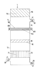
FIG. 2 shows a schematic view of an embodiment of an evaporator according
to the invention, which as a whole is labeled with reference number 1. The
evaporator 1 is not specifically limited as to form, shape, construction or
composition unless specifically indicated otherwise. Any suitable material
that
can be fabricated can be made into an evaporator 1. For reasons of economy,
evaporators are often made from stainless steel or another material indicated
for the specific application. Evaporator internal components are generally
made from metals depending upon the process requirements. In one
embodiment the evaporator 1 and its components are constructed of metals.
Suitable metals include carbon steel, stainless steel, nickel alloys, copper
alloys, titanium and zirconium.
The embodiment in FIG. 2 shows a substantially vertical evaporator 1, but it
will be understood by one skilled in the art that other orientations of the
evaporator 1 are possible, so long as technically feasible.
Evaporators and their construction and operation are well known in the art,
for
example, as disclosed in Handbook of Evaporation Technology, by P.E.
Minton, published in 1986 by Noyes (ISBN 0-8115-1097-7), Fundamentals
and modeling of separation processes: absorption, distillation, evaporation
and extraction, by C.D. Holland, published in 1975 by Prentice-Hall (ISBN 0-
13-344390-6), and Selecting Evaporators For Process Applications, by W.B.
Glover, Chemical Engineering Progress, Dec. 2004, p. 26 ¨ 33,
www.cepmagazine.org. Unless indicated otherwise, conventional construction
CA 02894199 2015-06-08
WO 2014/090431 PCT/EP2013/071063
- 14 -
materials and means, as well as components and auxiliaries, may be used for
the evaporator 1, and the column 1 may be operated in an evaporation
process in a conventional manner as known in the art. For example, these
cited reference handbooks and textbooks disclose a variety of conventional
means for evaporating, heat exchanging and condensing for use in
evaporators.
The evaporator 1 is adapted for a counter-current flow of at least one liquid
and one vapor therein and comprises within one common vessel 12, all in
fluid and/or vapor communication with one another: a first inlet 21 for a
first
liquid feed stream 30, a first outlet 41 for a first liquid output stream 50,
a
second outlet 42 for a first vapor stream 60, an evaporator sub-unit 70
comprising an evaporating means 71 for evaporation of a liquid to produce a
vapor, an internal sub-unit 90 having a surface 92 embodied such that a
contact is provided between a vapor and a liquid and a mass transfer is
provided between the vapor and the liquid, a heat exchanger sub-unit 100
comprising a heat exchanging means 102 embodied such that a heat
exchange is provided between a liquid stream 300, preferably the feed stream
30 or a cooling or heating stream (not shown in the Figures), and a liquid or
vapor contained within the evaporator 1, and a condenser sub-unit 110
comprising a condensing means 112 for condensing the vapor to a
condensate, wherein the internal sub-unit 90 is located substantially above
the evaporator sub-unit 70, the heat exchanger sub-unit 100 is located
substantially above the evaporator sub-unit 70, preferably substantially above
the internal sub-unit 90, and the condenser sub-unit 110 is located
substantially above the heat exchanger sub-unit 100 and the internal sub-unit
90. Note: the internal sub-unit 90 and its surface 92 are located above the
evaporator sub-unit 100 but below the heat exchanger sub-unit 100 in the
specific embodiment shown in FIG. 2.
The liquid streams 30 and 50 and vapor stream 60 are not specifically limited
and each may comprise one or more organic compounds, solvents, water or
mixtures thereof.
CA 02894199 2015-06-08
WO 2014/090431 PCT/EP2013/071063
- 15 -
The evaporator sub-unit 70 comprises an evaporating means 71 for
evaporation of a liquid to produce a vapor, which is conventional as known in
the art and not specifically limited. The evaporating means 71 evaporates a
liquid to a vapor as it passes in countercurrent flow through sub-unit 70.
Suitable evaporating means 71 may comprise one or more heated surfaces
80, wherein the surfaces 80 are preferably those of tubes, channels, or
plates.
The internal sub-unit 90 has a surface 92 embodied such that a contact is
provided between a vapor and a liquid and a mass transfer is provided
between the vapor and the liquid. The sub-unit 90 is conventional as known in
the art and not specifically limited, and, for example, it may be an
impingement separator of the wire mesh, vane, swirl or demister type. In a
preferred embodiment, internal sub-unit 90 is a mist eliminator sub-unit 94
for
eliminating a mist.
The heat exchanger sub-unit 100 comprises a heat exchanging means 102
embodied such that a heat exchange is provided between a liquid stream 300,
preferably the feed stream 30 or a cooling or heating stream (not shown), and
a liquid or vapor contained within the evaporator 1. The liquid stream 300 may
be used after the heat exchange in the evaporator 1, e.g. as the feed stream
30, or it may be used as a feed stream for another system. The heat
exchanger sub-unit 100 and means 102 are conventional as known in the art
and not specifically limited. For example, the sub-unit 100 may be of the
tubular, plate, extended surface, regenerative, shell and tube types, and the
flow arrangement may be single pass, such as counter, parallel, cross, split
or
divided flow types. In a preferred embodiment (not shown in Fig. 2, but shown
in Fig. 4), the heat exchanger sub-unit 100 is a feed preheater sub-unit 105
for preheating the feed stream 30.
The condenser sub-unit 110 comprises a condensing means 112 for
condensing the vapor to a condensate. The condenser sub-unit 110 and
means 112 are conventional as known in the art and not specifically limited,
and, for example, the sub-unit 110 may be a surface condenser such as a
CA 02894199 2015-06-08
WO 2014/090431 PCT/EP2013/071063
- 16 -
shell and tube heat exchanger, or a Liebig, West, Allihn, Davies, Graham,
coil,
Dimroth, spiral, or Friedrichs condenser. The coolant may be air, water, or
other gaseous, liquid or solid coolant.
The common vessel 12 is not specifically limited as to form, shape or
composition. In the embodiment shown in FIG. 2 it is cylindrical in shape. The
first inlet 21, first outlet 41, and second outlet 42 are all conventional, as
known in the art. The first inlet 21 is located in a lower portion of the
vessel
13, preferably substantially above the evaporator sub-unit 70, the first
outlet
41 is located substantially below the evaporator sub-unit 70, and the second
outlet 42 is located substantially above the evaporator sub-unit 70 and the
first
inlet 21. The locations of the inlet 21 and outlets 41 and 42 within the
evaporator 1 are not specifically further limited. In the embodiment shown in
FIG. 2 the inlet 21 is located substantially below the evaporator sub-unit 70.
One skilled in the art will understand that the reverse geometry thereof is
within the scope of the invention.
In the embodiment shown in FIG. 3, the internal sub-unit 90 and its surface 92
are located above both the evaporator sub-unit 70 and the heat exchanger
sub-unit 100 and in which within the common vessel 12 of the evaporator 1 is
a falling film evaporator sub-unit 72 comprising one or more heated surfaces
80, a static section 130, a second collector 154 and a distributor 160.
As shown in FIG. 3, in several preferred embodiments the one or more heated
surfaces 80 are substantially vertical in order to make use of gravity as a
force. In some embodiments the surfaces 80 are preferably those of tubes,
channels, or plates in order to have a large surface area and favorable flow
properties.
One skilled in the art will understand that other arrangements of the static
section 130 and the collector 154 and distributor 160 are possible. In some
preferred embodiments the one or more sections 130 are located substantially
above the evaporator sub-unit 70 and substantially below the condenser sub-
unit 110. For example, in one embodiment the static section 130, collector
CA 02894199 2015-06-08
WO 2014/090431 PCT/EP2013/071063
-17-
154, and distributor 160 are all above internal sub-unit 90, and in another
embodiment the collector 154 and distributor 160 collect liquid from and
distribute liquid to the evaporator sub-unit 70, respectively.
Each static section 130 comprises a packing and/or trays. In one preferred
embodiment structured packing is used due to its superior performance. In
certain embodiments the packing comprises mass transfer elements known in
the art as random packings, such as Raschig and/or Pall rings, saddles, such
as e.g. Berl saddles, spheres, hooks, or by the tradenames NORPACTM, B10-
NETTm, or HelXTM. In certain other embodiments, the packing comprises
structured packings such as those known by the trademarks MellapakTm,
MontzPakTM, RaluPakTM, SMVTm, or Raschig SuperPakTM. In another
preferred embodiment, a combination of trays and structured packing is
made, preferably one in which a dual flow tray is located in between each
packing element.
The collector 154 and distributor 160 are conventional and well-known in the
art for the collection or distribution of liquids in separation devices such
as
columns or evaporators. Collector types include chimney tray, Chevron-type,
trough liquid, and deck liquid collectors. Collectors are typically used for
total
draw-off of a liquid to product or pump-around pump down loops, partial draw-
off of a liquid with overflow continuing down the evaporator 1, or the
collection
of liquid for mixing. Typically Chevron-type and trough liquid collector
plates
require less height than deck-style collectors, and thus they are preferred
where height is limited.
One skilled in the art will understand that that the performance of an
evaporator sub-unit 70 and/or static section 130 can be significantly affected
by how uniformly the feed and solvent inlet streams are distributed to their
cross section. The requirements for distribution and redistribution vary
depending upon the type of internals (packing, trays, agitators, or baffles)
and
the impact of the internals on the flow of dispersed and continuous phases
within the evaporator 1. Important aspects of the distributor 160 include the
CA 02894199 2015-06-08
WO 2014/090431 PCT/EP2013/071063
- 18 -
number of holes and the hole pattern (geometric layout), hole size, number of
downcomers or upcomers (if used) and their placement, the maximum to
minimum flow rates the design can handle (turndown ratio), and resistance to
fouling. Liquid distributors are typically used to achieve uniform liquid
distribution across the evaporator cross section, and distributors 160 will
often
be located above the evaporator sub-unit 70 and/or the static section 130.
Useful distributor 160 types include splash plate, channel types with bottom
holes or lateral tubes, pipe orifice, chimney tray, ladder type, pan, deck,
trough, pipe arm, trickling or spraying device, spray condenser, sprinkler,
spray, and weir overflow distributors.
FIG. 4 shows a schematic view of yet another preferred embodiment of an
evaporator 1 according to the invention, in which within the common vessel 12
a mist eliminator sub-unit 94 for eliminating a mist is located above both the
evaporator sub-unit (Note: In this figure it is more specifically a falling
film sub-
unit 72) and below the feed preheater sub-unit 105, and in which within the
common vessel 12 of the evaporator is a falling film evaporator sub-unit 72
comprising one or more heated surfaces 80, a first collector 150 having a
jacket 152 for providing thermal isolation, and a second collector 154. The
double-wall jacketing acts as a thermal insulation and reduces the re-
evaporation of collected condensate and condensation on the bottom side of
the first collector 150. The collected condensate may be fully or partially
withdrawn or used in refluxing in the case of a reflux condenser.
As exemplified by this specific embodiment in FIG. 4, the evaporator 1 may
also additionally comprise a boot 120 contained within the lower portion 13 of
the common vessel 12 and located substantially below the evaporator sub-
unit 70, which is a falling film evaporator sub-unit 72 in this specific
embodiment. The boot 120 is not specifically limited as to form, shape,
construction or composition unless specifically indicated otherwise. In order
to
minimize liquid hold-up, the boot 120 will generally have a diameter that is
smaller than the diameter of the lower portion 13 of the common vessel 12. In
order to minimize the use of piping and thus residence time and degradation,
CA 02894199 2015-06-08
WO 2014/090431 PCT/EP2013/071063
- 19 -
it will be preferred that the boot 120 is contained within the common vessel
12. For the case of liquids having suspended solids, it will be preferred to
locate the first outlet 41 on the side rather than the bottom of the boot 120
so
as to allow the solids to settle to the bottom of the boot 120 and be removed.
FIG. 5 shows a preferred embodiment of the liquid distributor 160 for
distribution to a falling film evaporator. In this embodiment, the liquid
flows first
thru a channel 200 and at the end of the channel into a ring channel 210 and
from there flows thru openings 220 onto the tube plate 230 comprising vertical
tubes 240. Such a preferred design of the distributor 160 allows an optimal
distribution of liquid to the falling film evaporator while still remaining
relatively
"open" to allow the rising vapor to pass in counter-current flow to the
descending liquid.
In order to minimize pressure losses in the evaporator 1 in many preferred
embodiments, a means other than piping 1200' is used for leading the liquid
and the vapor between any of the sub-units 70, 90, 100, and 110. As can be
seen from the embodiments in Fig. 1 ¨ 4, the use of piping 1200' may be
avoided by locating the sub-units near each other within one common vessel
12 such that the sub-units are all in fluid and/or vapor communication with
one
another.
In order to minimize investment and maintenance costs, moving parts are
absent within the common vessel 12 in several preferred embodiments of the
evaporator 1.
Although not shown in the schematic figures for simplicity, one skilled in the
art will understand that other conventional evaporator and separation device
internals may be used without limitation in the invention, such as feed
devices
like feed pipes and/or sumps, bed limiters, support plates and grids,
dispersers, disperser/support plates, continuous phase distributors, packing
support and hold-down plates, entrainment separators, and
retainers/redistributors. Suitable internals are disclosed for example in the
CA 02894199 2015-06-08
WO 2014/090431 PCT/EP2013/071063
- 20 -
technical brochure "Internals for Packed Columns" from Sulzer Chenntech as
publication 22.51.06.40 ¨ X11.09 ¨ 50.
Auxiliaries for the evaporator 1 are conventional and well-known in the art
and
include electrical supplies, coolant and heating fluid supplies and
distributions,
level controllers, pumps, valves, pipes and lines, reservoirs, drums, tanks,
and
sensors for measuring such parameters as flow, temperatures and levels. The
evaporator 1 and the separation process will be conveniently controlled by
means of a computer interface equipped with appropriate sensors.
Another aspect of the invention is a process to separate at least two
components, wherein to an evaporator 1 of the invention, a first liquid feed
stream 30 comprising the at least two components is fed by means of the first
inlet 21, the feed stream 30 passes into the evaporator sub-unit 70, in which
a
vapor stream 32 is formed from the feed stream 30 by means of heat and
mass transfer, preferably in contact with the heated surfaces 80, wherein the
vapor stream 32 exits in a substantially upward direction from the sub-unit
70,
and wherein the remaining non-vaporized feed stream 31 exits in a
substantially downward direction from the sub-unit 70 and is subsequently
removed as a first liquid output stream 50 comprising a first component of the
at least two components by means of the first outlet 41. The vapor stream 32,
optionally containing a mist, passes into the internal subunit 90, in which
the
mist, if present, is removed from the vapor stream 32, and the mist is,
optionally collected, withdrawn from the evaporator 1 and/or returned by
means of gravity to the evaporator sub-unit 70, the vapor stream 32 passes
into the heat exchanger sub-unit 100, in which a heat transfer occurs between
the vapor stream 32 and a liquid stream 300, preferably the feed stream 30 or
a cooling or heating stream (not shown in Figures), wherein, if the liquid
stream is the feed stream 30 the heat transfer occurs prior to the feed stream
passing into the vessel 12 through the first inlet 21, and wherein a first
portion of the vapor stream 32' is condensed within the condenser sub-unit
30 110 to form a first condensed stream 36 which is partially or fully
withdrawn
from the evaporator 1 and/or returned by means of gravity to the evaporator
CA 02894199 2015-06-08
WO 2014/090431 PCT/EP2013/071063
-21 -
sub-unit 70 and a second non-condensed portion of the vapor stream 32" is
removed as a first vapor stream 60 comprising a second component of the at
least two components by means of the second outlet 42. An example specific
embodiment of such a separation process of the invention is illustrated
schematically in FIG. 3 for the case of that specific embodiment of the
evaporator 1.
Evaporation processes are well known in the art, for example, as disclosed in
the earlier cited text- and reference books. Unless indicated otherwise,
conventional evaporation processes and their various liquid feed streams 30
and operating parameters and conditions may be used in the evaporation
processes according to the invention and making use of the evaporator 1.
This separation process of the invention has the benefit of making possible a
reduction in the operating temperature of the process. This is both more
economical and makes the process milder, thereby minimizing problems of
thermal degradation and decomposition of thermally-sensitive fine
compounds. In preferred embodiments, the feed stream 30 and the first liquid
output stream 50 comprise a compound having a thermal degradation
temperature of from 10 to 300, preferably from 20 to 275, most preferably 30
to 250 C, and preferably one having a viscosity at the operating temperature
of less than or equal to 20, preferably 10, most preferably 2 millipascal-
second. In the present application, the "operating temperature" concerning the
viscosity value refers to the measured temperature of the liquid in the lower
portion 13 within the common vessel 12. As an example, several heavy fatty
acid monoesters have viscosities of between about 8 to about 1 millipascal-
second as their temperatures vary from about 40 to about 240 C. The
evaporation process of the invention is particularly well suited for the
removal
of solvents from such thermally-sensitive compounds. In some preferred
embodiments, the feed stream 30 and the first vapor stream 60 comprise a
solvent.
CA 02894199 2015-06-08
WO 2014/090431 PCT/EP2013/071063
- 22 -
In many preferred embodiments of the process, a relatively low operating
temperature is achieved by means of a suitably low pressure within the
evaporator sub-unit 70, in some preferred embodiments the pressure is less
than 10, preferably 5, more preferably 2, most preferably 1 mbar.
Yet another aspect of the present invention is the use of the evaporator 1 or
the separation process of the invention in the purification and/or
concentration
of a compound having a thermal degradation temperature of from 10 to 300,
preferably from 20 to 275, most preferably 30 to 250 C, and preferably one
having a viscosity at the operating temperature of less than or equal to 20,
preferably 10, most preferably 2 millipascal-second, and/or in the removal of
a
solvent, or in the separation of a compound having a boiling point under
atmospheric pressure at a temperature above its thermal decomposition
temperature. As discussed earlier, the evaporator 1 and process of the
invention bring significant benefits when separating such compounds.
EXAMPLES
The following examples are set forth to provide those of ordinary skill in the
art
with a detailed description of how the evaporator 1 adapted for a counter-
current flow of at least one liquid and one vapor therein, processes, and uses
claimed herein are evaluated, and they are not intended to limit the scope of
what the inventors regard as their invention.
In these examples, the evaporator and process of the invention were
successfully used in a typical application for the purification of a heavy
fatty
acid monoester composed of a C8 alcohol and a C18 fatty acid. The fatty acid
monoester had a normal boiling point of about 465 C, about 250 C at 10
mmHg, and about 215 C at 1 mm Hg. The fatty acid monoester had a
thermal decomposition temperature of about 250 C. The viscosity of the
monoester was about 1 millipascal-second at about 220 C.
In particular, the purification was carried out using an evaporator 1 as shown
in FIG. 4. The evaporation took place at a reduced pressure of less than 4
CA 02894199 2015-06-08
WO 2014/090431 PCT/EP2013/071063
- 23 -
mbar (top pressure) measured at the second outlet 42 for the first vapor
stream 60 as shown in Figure 4. The pressure measured over the liquid level
in the lower portion 13 of the common vessel 12 was about 1 mbar greater
than the top pressure. A temperature of less than 240 C was measured in the
boiling liquid contained in the boot 120.
During stable operation the heavy fatty acid monoester could be produced
with the desired quality. For example, the acid number was less than 0.25 mg
KOH/g, and it remained constant relative to that of the feed to the
evaporator.
Furthermore the heavy fatty acid monoester obtained was colorless and had
color indices Y (yellow) and R (red) of both less than 1, and had no
detectable
turbidity. In contrast, the residue obtained from the bottom of the evaporator
was dark brown in appearance. The feed to the evaporator contained di- and
triglyceride components; however, these components were undetectable in
the distilled monoester product. The residual concentration of monoester in
the first liquid output stream 50 (bottom residue) removed via the first
outlet
41 was less than 80 % (corresponding to less than 1 % of the feed in this
example).
In a second comparative trial, a purification of the same feed stream
containing the same heavy fatty acid monoester was carried out on an
evaporator system according to the prior art, similar to the one shown in FIG.
1, and with a comparable specific evaporation rate as in the previous
example. However, the desired product quality could not be achieved in this
system of the prior art because of the significant pressure drop over the
entire
unit. Although the pressure after the condenser could be reduced to about 2
mbar, the temperature of the boiling liquid was however greater than 250 C.
This temperature correlates for this same ester composition with a pressure
drop of more than 4 mbar. The minimum operating temperature achievable in
this prior art system was therefore about 10 C higher than that obtainable
with the evaporator and process of the invention. This higher operating
temperature resulted in significant thermal degradation and discoloration of
the monoester product obtained.
CA 02894199 2015-06-08
WO 2014/090431 PCT/EP2013/071063
- 24 -
While various embodiments have been set forth for the purpose of illustration,
the foregoing descriptions should not be deemed to be a limitation on the
scope herein. Accordingly, various modifications, adaptations, and
alternatives can occur to one skilled in the art without departing from the
spirit
and scope herein.