Note: Descriptions are shown in the official language in which they were submitted.
1
DEVICE FOR HANDLING DRILL STRING COMPONENTS OF A DRILL STRING,
METHOD FOR HANDLING DRILL STRING COMPONENTS AND ROCK DRILLING RIG
FIELD
The present invention relates to a handling device for a
rock drill rig for handling drill string components for a drill
string, wherein a gripping device for gripping a drill string
component is displaceable between a drill string position in the
rock drill rig and a delivering position outside the rock drill
rig. The invention also relates to a method and a rock drill rig.
BACKGROUND
During drilling of long bore holes for e.g. exploration
drilling, considerable time is consumed for handling drill string
components during drilling, when the drill string is subsequently
lengthened, as well as for replacement of drill bit which has to
be performed regularly because of ongoing wear of drill bits
during drilling.
Different suggestions have been made to facilitate this
handling, one of which being a handling device for a rock drill
rig being previously known from AU-B-64377/96, wherein drill
string components are brought into a supporting device in the
form of a one way sleeve for the transfer of the drill string
component between a horizontal and a vertical position. This
known device does not provide stable handling of the drill string
components.
SUMMARY
One aim of the present invention is to provide a device as
mentioned initially which allows flexible and still secure
handling of drill string components.
CA 2894259 2020-03-18
2
According to a broad aspect, this aim is obtained with a
handling device for a rock drill rig for a handling drill string
component for a drill string being driveable by a rotator that is
displaceable along a feed beam of the rock drill rig, the
handling device comprising: a gripping device for gripping the
drill string component, the gripping device being displaceable
between a drill string position in the rock drill rig and a
delivering position outside the rock drill rig; a linear guide to
be arranged in connection with and in parallel with the feed
beam; a slide being displaceable along the linear guide; a swing
arm configured to support the gripping device, the swing arm
being supported by the slide; a first rotator; a swing arm
support connected to the slide, the swing arm support and the
first rotator being configured to swing drive the swing arm and
the supported gripping device around a first rotational axis
being parallel to and at a distance from a longitudinal axis of
the drill string component when being gripped by the gripping
device; a second rotator configured to swing drive with respect
to the slide, the swing arm support, the swing arm and the
supported gripping device around a second rotation axis, the
second rotation axis forming an angle with a longitudinal axis of
the linear guide and forming an angle with the first rotational
axis, and a third rotator configured to swing the gripping device
to the drill string position and to further swing drive the swing
arm support, the swing arm and the supported gripping device
around a third rotational axis parallel to the linear guide.
According to another broad aspect, there is provided a rock
drill rig comprising a rotator being displaceable along a feed
beam and a handling device, the handling device comprising: a
linear guide to be arranged in connection with and in parallel
with the feed beam; a slide being displaceable along the linear
guide; a first rotator; a swing arm configured to support a
CA 2894259 2020-03-18
3
gripping device, the swing arm being supported by the slide; a
swing arm support connected to the slide, the swing arm support
and the first rotator being configured to swing drive the swing
arm and the supported gripping device around a first rotational
axis being parallel to and at a distance from a longitudinal axis
of a drill string component when being gripped by the gripping
device; a second rotator configured to swing drive with respect
to the slide, the swing arm support, the swing arm and the
supported gripping device around a second rotation axis, the
second rotation axis forming an angle with a longitudinal axis of
the linear guide and forming an angle with the first rotational
axis; and a third rotator configured to swing the gripping device
to a drill string position and to further swing drive the swing
arm support, the swing arm and the supported gripping device
around a third rotational axis parallel to the linear guide.
Hereby a flexible handling device is provided which is
capable of performing accurate transfers of drill string
components, on the one hand into the drill string position
because of the combination of the construction of the gripping
device with axially separated gripper pairs and the extensive
control possibilities being offered through the three specially
positioned rotators. By swinging the swing arm around the first
rotational axis, the gripping device can be turned for example in
against and out from the drill string position. It also results
in that the gripping device can be fine adjusted in order to grip
a drill string having a position somewhat deviating from an exact
delivering position. A turning radius for swinging of a drill
string component is also adjustable, for example to different
sized feed beams being applied according to the invention.
The combination of the ability to swing and the slide being
displaceable along the linear guide allows that the delivering
position is easily varied in vertical direction for the freedom
CA 2894259 2020-03-18
4
of positioning magazines of different sizes and heights, and such
that even magazine having a plurality of horizontal levels can be
used in connection with the invention.
With "delivering position" is here intended a position of a
drill string component to be gripped by the gripping device
(pick-up position), as well as a position for a drill string
component to be released by the gripping device (release
position). This can normally be a defined position in a magazine,
but it can also be another specified position of a drill string
component intended to be gripped or released.
The linear guide is preferably a separate unit being
attachable to the feed beam. Hereby it can be arranged for a
standard rig without requirements to amend the feed beam etc. It
can also be applied in an existing rig without major
modifications thereto. It should, however, be noted that it is
possible within the scope of the invention to construct the
linear guide as a unit together with the feed beam.
The third rotational axis is preferably positioned between
the linear guide and fastening points therefore on the feed beam,
wherein the ability to swing around the third rotation axis,
being parallel to the linear guide, also includes swing driving
the linear guide. This gives possibility of having a great
movement range of the handling device and allows higher degree of
rigidity of components supporting the slide compared to if the
third rotational axis would be positioned between the slide and
the gripping device.
It is particularly preferred that the gripping device is
supported axially displaceably drivable along a swing arm, as
seen in an axial direction of a gripped drill string component.
This gives advantages in respect of positioning the gripping
device in axial direction in respect of a drill string component
to be gripped. Not least in combination with the displaceability
CA 2894259 2020-03-18
5
along the linear guide. Further, the displaceability along the
swing arm allows increased possibilities of adjusting a
delivering position for drilling operations in different
inclinations of the feed beam and thereby the linear guide. This
displaceablity along the swing arm is suitably realised with the
aid of a hydraulic cylinder.
A support for the second rotator is suitably rigidly
connected to the slide. It is further preferred that a first exit
axis, protruding from the first rotator, is rigidly connected to
the swing arm, and that a second exit axis protruding from the
second rotator is rigidly connected to a main portion of the
first rotator. This allows a stable and compact construction.
It is preferred that the second rotational axis forms
essentially a right angle to the linear guide as well as to the
first rotational axis.
The linear guide preferably includes a linear driving
device for the slide in the form of chain drive or a hydraulic
cylinder.
The handling device preferably also includes a magazine
having support members for supporting drill string components.
These units can be tuned to each other in an advantageous way for
achieving co-adjustment of the movement pattern thereof. The
magazine is suitably displaceably connected to the rock drill
rig, which is advantageous for adapting to i.a. an existing
inclination of the feed beam. In particular the magazine is
displaceable in directions in parallel to axial directions of
drill string components being received in the magazine.
The magazine preferably includes support members in the
form of component brackets in a plurality of levels, wherein the
component brackets on one level are removable for allowing access
to drill string components on a lower level.
CA 2894259 2020-03-18
6
Said support members are suitably arranged for receiving a
plurality or drill string components on the same level, wherein
said support members are adjustable to incline towards the
delivering position when it is a pick-up position for the
gripping device, and from the delivering position when it is a
release position for the gripping device.
The gripping device has preferably a considerable axial
extension in relation to the length of a drill string component
and preferably includes at least two axially separated gripper
pairs in order to achieve stable gripping of a drill string
component for minimal tendency to wobble.
According to a further broad aspect, there is provided a
method for handling a drill string component of a drill string of
a rock drill rig, the drill string being driveable by a rotator
that is displaceable along a feed beam of the rock drill rig, the
method comprising: displacing a slide along a linear guide to be
arranged in parallel with the feed beam; gripping the drill
string component with a gripping device being supported by the
slide; displacing the gripping device between a drill string
position in the rock drill rig and a delivering position outside
the rock drill rig; swinging a swing arm supporting the gripping
device with respect to a swing arm support being connected to the
slide around a first rotational axis, being parallel to and at a
distance from a longitudinal axis of the drill string component
when being gripped by the gripping device; swinging the swing arm
support and the swing arm with the supported gripping device with
respect to the slide around a second rotation axis, the second
rotation axis forming an angle with a longitudinal axis of the
linear guide and forming an angle with the first rotational axis,
and swinging the swing arm support and the swing arm with the
supported gripping device around a third rotational axis parallel
CA 2894259 2020-03-18
7
to the linear guide for swinging the gripping device to the drill
string position.
Through this method, advantages are achieved corresponding
to what is related to the inventive device.
Features corresponding to subordinate device features
according to the above are applicable in connection with the
inventive method and result in corresponding advantages.
The invention also relates to a rock drill rig having a
rotator being displaceable along a feed beam and including an
inventive handling device.
BRIEF DESCRIPTION OF DRAWINGS
The invention will now be described in greater detail by
way of embodiments and with reference to the drawings. In the
drawings:
Fig. 1 shows a rock drill rig equipped with a feed beam for
a rock drilling machine and a linear guide for a device for
handling drill string components,
Fig. 2 shows the device for handling drill string
components in Fig. 1 separated from the feed beam and in a
greater scale,
Fig. 3 shows an enlarged view of a detail of the device for
handling drill string components in a greater scale,
Fig. 4 shows the device of Fig. 2 in another position,
Fig. 5 shows diagrammatically a block diagram of a sequence
of a method according to the invention, and
Figs. 6 a, b, c and d show diagrammatically the movements
of the device during a method sequence.
DETAILLED DESCRIPTION OF EMBODIMENTS
Variants, examples and preferred embodiments of the
invention are described hereinbelow. Fig. 1 shows
CA 2894259 2020-03-18
7a
diagrammatically a rock drill rig 1, which is equipped with a
feed beam 2 whereon a (drilling machine) slide 3 supporting a
rock drilling machine 4 is movable to and fro. On the feed beam 2
there is fastened a device 5 for handling drill string components
including a linear guide 6 whereon a (handling) slide 7 with a
gripping device 8 is movable to and fro.
The device for handling drill string components 5 is
arranged to handle drill string components being stored in a
magazine (not shown) for drill string components close to the
rock drill rig and to successively position them in a drill
string position of the rock drilling machine 4. The device for
handling drill string components 5 is also arranged to
successively remove drill string components from the drill string
position and place them in said magazine when the drill string is
taken out from a bore hole, for example when it is time to
replace the drill bit.
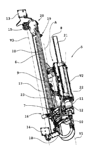
In Fig. 2, the linear guide 6 is shown and the to and fro
movable slide 7, whereon is attached the gripping device 8
which includes two axially separated gripper pairs 9 as seen in
an axial direction of a gripped drill string component. The
gripping device 8 is supported axially displaceable along a swing
arm 21, also seen in an axial direction of a gripped drill string
component. The swing arm 21 is connected to a swing arm fastener
22 and is in turn, with supported gripping device 8, and in
respect to the slide 7, swing drivable with the aid of a first
rotator 11 around a first rotational axis V1 being parallel to
and at a distant from an axis A of a drill string component (not
shown) being gripped by the gripping device.
Through this ability to be swing driven, the position of
the gripping device can be fine adjusted laterally, e.g. prior
CA 2894259 2020-03-18
CA 02894259 2015-06-08
WO 2014/098708 PCT/SE2013/051375
8
to gripping a drill string component in order to overcome
unintentional deviation from a desired delivering position.
The swing arm 21 with supported gripping device 8 is
swing drivable by a second rotator 12, in respect of a support
23 and the slide 7, around a second rotational axis V2 forming
an angle with the linear guide 6 as well as with the first
rotational axis Vi. This swingability results in that the
swing arm 21 can be swung from a position where it is parallel
to the linear guide 6 to positions for forming an angle
between the swing arm 21 and the linear guide 6.
The swing arm support 22 and thereby the swing arm 21
with supported gripping device 8 is further, with the aid of a
third rotator 15, swing drivable around a third rotational
axis V3 being parallel to the linear guide 6, for swinging the
gripping device into the drill string position.
In this case the third rotational axis V3 is positioned
between the linear guide 6 and fastening points therefore on
the feed beam 2, whereby the ability to be swing driven around
the third rotational axis V3, being parallel to the linear
guide 6, also includes swing driving the linear guide 6. The
device 5 for handling drill string components is thus in this
case fastened to the feed beam 2 over a first support 13 and a
second support 14. The linear guide 6 with supported slide 7
(and components carried by the slide) is swingable in respect
of the supports 13 and 14 and to the feed beam by a third
rotator 15 around the third rotational axis V3.
The gripping device 8 also provides an axial stop 10 for
a gripped drill string component.
In the shown embodiment, the first rotational axis V1 is
perpendicular to the second rotational axis V2 which in turn
is perpendicular to the third rotational axis V3. The second
rotational axis V2, however, is positioned at a distance from
CA 02894259 2015-06-08
WO 2014/098708
PCT/SE2013/051375
9
and does not intersect either with the first rotational axis
V1 or with the third rotational axis V3.
The slide 7 is further equipped with a safety brake 16
which co-operates with a brake beam 17 being arranged along
the linear guide 6 and being provided with a brake surface on
each side. The safety brake 16 is in the shown example a
normally locked clamping brake which in unloaded condition
clamps on the brake beam 17 such that the slide 7 with
associated gripping device 8 is locked in respect of the
linear guide for preventing that the slide with the gripping
device, possibly with gripped, heavy drill string component,
falls to a lowermost position, whereby serious risks for
injury on the operator and possible other persons in the
vicinity could occur.
The slide 7 also has other means for co-operation with a
drive chain, which is indicated with interrupted lines at 18.
This drive chain is driven by a driver device 19, partly
being shown in Fig. 2, for a movement to and fro of the slide
7 along the linear guide 6. The drive chain is positioned in a
loop so that it co-operates with the driver device 19 over a
drive transmission 20 and a not shown freely rotatable chain
wheel positioned at the lower part of the linear guide 6, as
it is shown in Fig. 2.
Fig. 3 shows the arrangement of the slide 7 in greater
scale, and in a somewhat altered perspective for clarifying
purposes. The slide has here been brought to an upper position
close to the first support 13. A hydraulic cylinder 48 is
arranged along the swing arm 21 for driving the gripping
device 8 to and fro.
Fig. 4 shows the device 5 with the swing arm 21 swung
down around the axis V2 such that it together with the
gripping device 8 is in a horizontal position, normally suited
for gripping a drill string component. Since the slide 7 is
CA 02894259 2015-06-08
WO 2014/098708 PCT/SE2013/051375
displaceable up and down along the linear guide 6 and the
gripping device is displaceable along the swing arm 21, the
gripping device can be adjusted vertically as well as
longitudinally in order to be adequately positioned to a drill
5 string component to be gripped. Further, swingability around
the axis V1 allows possibility of adjustment laterally in case
this could be required.
Fig. 5 shows a block diagram of a sequence of a method
for handling and in this case gripping and positioning of a
10 drill string component to a drill string position according to
the invention, wherein:
Position 41 indicates the start of the sequence.
Position 42 indicates that the gripping device with open
gripper pairs is aligned to a drill string component in a
delivering position in a magazine by rotating the swing arm
and possibly axially displacing the gripping device thereon.
Position 43 indicates that the gripping device is brought down
to a grip position of the gripper pairs by swinging the swing
arm and/or displacing it downwards of the slide with supported
gripping device. See Fig. 6a.
Position 44 indicates that the gripper pairs of the gripping
device is brought to grip the drill string component.
Position 45 indicates that the slide with the gripped gripping
device is displaced upwardly, the swing arm is swung upwardly
to a position where it is essentially parallel to the linear
guide. See Fig. 6b. The swing arm is now swung such that the
gripping device is redirected about 180 . See Fig. 6c.
Position 46 indicates that the third rotator is activated for
swinging of the drill string component to the drill string
position. See Fig. 6d.
Position 47 indicates threading together of the drill string
component with a component belonging to the drill string by
activating the rotator of the rock drill rig, opening the
CA 02894259 2015-06-08
WO 2014/098708 PCT/SE2013/051375
11
gripper pairs, removing the gripping device from the drill
string component and thereupon ending the sequence.
The different swing movements can in certain cases occur
overlapping and in reverse order which is obvious to the
person skilled in the art. In certain cases the drill string
component needs to be axially displaced and be re-gripped
within the scope of the sequence step of position 44 in order
to ensure that the end of the drill string component abuts an
end stop being associating with the gripping device.
The invention can be varied within the scope of the
following claims. The rotators can be arranged differently and
with other mutual angles than what is shown on the Figures.
It is possible to supplement the device according to the
invention with an automatic control for positioning, gripping
and transferring drill string components between a drill
string position in a rig and a magazine.
With reference to Fig. 6a, the handling device 5 suitably
includes a magazine 99 having support members 98 for drill
string components 100. The magazine is suitably displaceably
connected to the rock drill rig in order to facilitate
positioning in different angular positions of the feed beam.
In particular, the magazine is suitably displaceable in
directions parallel to axial directions of drill string
components being received in the magazine. Further, it is
preferred that the magazine includes support members 98 in the
form of component brackets in a plurality of levels and that
the component brackets on one level are removable for access
to drill string components on a lower level, wherein suitably
said support members are arranged for receiving a plurality of
drill string components on the same level, wherein said
support members are adjustable for inclination towards the
delivering position when it is a pick-up position of the
CA 02894259 2015-06-08
WO 2014/098708 PCT/SE2013/051375
12
gripping device and from the delivering position when it is a
release position for the gripping device.