Note: Descriptions are shown in the official language in which they were submitted.
MULTI-STAGE DUCT FIRED HEAT RECOVERY STEAM GENERATOR
AND METHODS OF USE
Field
One or more embodiments relate to, for example, a multi-stage/high temperature
duct
fired heat recovery steam generator and related methods thereof.
Background
A heat recovery steam generator or HRSG is a heat exchange apparatus that
recovers heat from a hot gas stream to produce steam. The hot gas stream can
be provided,
for example, by the hot exhaust from a gas turbine. Gas turbines with no heat-
recovery steam
generators (HRSGs) are approximately 35 to 40% thermally efficient. Gas
turbines with
non-fired heat-recovery steam generators (HRSGs) are approximately 75 to 80%
thermally
efficient, wherein the HRSGs generate steam utilizing the energy in the gas
turbine exhaust,
the quality and quantity of which depend on flow characteristics and
temperature of the
exhaust gas. Typical gas turbine exhaust contains 13-15% oxygen by volume.
Prior art gas turbines with a single stage of duct firing (duct burner or
supplemental burner) are approximately 80 to 85% thermally efficient, because
any fuel
added to duct firing the HRSG is 100% thermally efficiency. Exhaust downstream
of a
single stage of duct firing contains approximately 10-12% oxygen by volume.
One reason
for the inefficiency of the prior art turbines is that significant amounts of
air are compressed
not only for combustion process, but also as cooling air for the turbine
combustor, vanes and
turbine blades.
The invention relates to a multi-stage / high temperature duct-firing HRSG,
which can utilize the remaining oxygen in the gas turbine exhaust down to less
than 5%, and
thereby increase the overall thermal efficiency significantly, e.g., at least
92%.
1
Date recue / Date received 2021-12-03
Summary
[0006] In one aspect, embodiments disclosed herein relate to a Multi-Stage
/High
Temperature duct-fired heat recovery steam generator HRSG exhibiting increased
efficiency
and steam volume production as compared to other heat recovery steam
generators.
[0007] In another aspect, the invention relates to a system to produce steam
for a
thermal enhanced oil recovery (EOR) operation using a heat recovery steam
generator
(HRSG) assembly. The system comprises: at least a feed water supply for
providing water
to be converted to steam; a gas turbine connected to an electrical generator
producing
electrical power, the gas turbine generates exhaust gas at a temperature of at
least 1000 F,
and wherein the exhaust gas contains at least 10% oxygen as available oxygen;
an exhaust
duct configured to receive the exhaust gas from the gas turbine; at least two
duct burners
arranged in at least two stages in series, a first duct burner and a
subsequent duct burner; at
least a gas supply for providing gas having a calorific range at least 1000
BTU/scf to the duct
burners; a plurality of evaporators for transferring heat from the duct
burners to the water to
generate steam, with at least one evaporator corresponding to each of the duct
burners,
wherein the at least one evaporator is arranged downstream from the
corresponding duct
burner; wherein the first duct burner in series is configured to receive the
exhaust gas from
the gas turbine thereby using the available oxygen in the exhaust gas and
reducing oxygen
concentration, and flow the exhaust gas having a reduced oxygen concentration
downstream
to the evaporator corresponding to the first duct burner, and then to the
subsequent duct
burner in series, wherein the subsequent duct burner in series is configured
to receive the
exhaust gas having a reduced oxygen concentration after the evaporator
corresponding to the
first burner, thereby further reducing the oxygen concentration in the exhaust
gas and flow
the exhaust gas having a further reduced oxygen concentration to the
evaporator
corresponding to the subsequent duct burner; wherein the evaporators are
arranged in
parallel with respect to receiving the feed water supply for converting water
into steam of at
least 65% steam quality; and wherein the exhaust gas exiting the HRSG assembly
contains
less than 5% oxygen concentration.
[0007a] In accordance with another aspect, there is a system to produce steam
for a
thermal enhanced oil recovery (EOR) operation, the system comprising:
at least one feed water supply that provides water to be converted to steam; a
gas
turbine connected to an electrical generator that produces electrical power,
wherein the gas
turbine generates exhaust gas at a temperature of at least 1000 F., and
wherein the exhaust
2
Date recue / Date received 2021-12-03
gas contains at least 10% oxygen as available oxygen; and a heat recovery
steam generator
(HRSG) assembly comprising:
an exhaust duct configured to receive the exhaust gas from the gas turbine;
at least two duct burners arranged in series that include a first duct burner
and a
subsequent duct burner, wherein each duct burner has a plurality of burner
sections arranged
in a generally vertical plane, and wherein at least one perforated plate is
located upstream of
the subsequent duct burner and is configured to disperse and distribute
available oxygen
within the subsequent duct burner;
at least a gas supply for providing gas having a calorific output of at least
1000
BTU/scf to the at least two duct burners and the gas turbine;
a plurality of evaporators for transferring heat from the at least two duct
burners to the
water to generate steam, wherein at least one evaporator corresponds to each
of the duct
burners, and wherein each at least one evaporator is arranged downstream from
its
corresponding duct burner relative to a flow of the exhaust gas;
wherein the first duct burner is arranged in series with the subsequent duct
burner
relative to the flow of exhaust gas and is configured to receive the exhaust
gas from the gas
turbine, use available oxygen in the exhaust gas thereby reducing oxygen
concentration, and
pass exhaust gas having a reduced oxygen concentration relative to the exhaust
gas from the
gas turbine downstream relative to the at least one evaporator corresponding
to the first duct
burner and then to the subsequent duct burner in series;
wherein the subsequent duct burner is configured to receive the exhaust gas
having a
reduced oxygen concentration after it has passed through the at least one
evaporator
corresponding to the first burner, further reduce oxygen concentration in the
exhaust gas, pass
exhaust gas having a further reduced oxygen concentration relative to the
exhaust gas with a
reduced oxygen concentration to the evaporator corresponding to the subsequent
duct burner;
wherein the plurality of evaporators are arranged in parallel with respect to
a flow of
feed water received from the at least one feed water supply;
wherein the plurality of evaporators are configured to convert water into
steam that
has a steam quality of at least 65%; and
wherein exhaust gas exiting the HRSG assembly contains oxygen in a range of 2%
to
8%.
[000713] In accordance with a further aspect, there is a method to produce
steam for
a thermal enhanced oil recovery (EOR) operation, the method comprising:
2a
Date recue / Date received 2021-12-03
providing at least one feed water supply that provides water to be converted
to steam;
providing a gas turbine connected to an electrical generator that produces
electrical
power, wherein the gas turbine generates exhaust gas at a temperature of at
least 1000 F, and
wherein the exhaust gas contains at least 10% oxygen as available oxygen; and
providing a heat recovery steam generator (HRSG) assembly comprising:
an exhaust duct configured to receive the exhaust gas from the gas turbine;
at least two duct burners arranged in series that includes a first duct burner
and
a subsequent duct burner, wherein each duct burner has a plurality of burner
sections
arranged in a generally vertical plane, and wherein at least one perforated
plate is
located upstream of the subsequent duct burner and is configured to disperse
and
distribute available oxygen within the subsequent duct burner;
at least a gas supply for providing gas having a calorific output of at least
1000
BTU/scf to the at least two duct burners and the gas turbine;
a plurality of evaporators for transferring heat from the at least two duct
burners to the water to generate steam, wherein at least one evaporator
corresponds to
each of the duct burners, and wherein each at least one evaporator is arranged
downstream from its corresponding duct burner relative to a flow of the
exhaust gas;
wherein the first duct burner is arranged in series with the subsequent duct
burner
relative to the flow of exhaust gas and is configured to receive the exhaust
gas from the gas
turbine, use available oxygen in the exhaust gas thereby reducing oxygen
concentration, and
pass exhaust gas having a reduced oxygen concentration relative to the exhaust
gas from the
gas turbine downstream relative to the at least one evaporator corresponding
to the first duct
burner and then to the subsequent duct burner in series;
wherein the subsequent duct burner is configured to receive the exhaust gas
having a
reduced oxygen concentration after it has passed through the at least one
evaporator
corresponding to the first burner, further reduce oxygen concentration in the
exhaust gas, pass
exhaust gas having a further reduced oxygen concentration relative to the
exhaust gas with a
reduced oxygen concentration to the evaporator corresponding to the subsequent
duct burner;
wherein the plurality of evaporators are arranged in parallel with respect to
a flow of
feed water received from the at least one feed water supply;
wherein the plurality of evaporators are configured to convert water into
steam that
has a steam quality of at least 65%; and
wherein exhaust gas exiting the HRSG assembly contains oxygen in a range of 2%
to
8%; and
2b
Date recue / Date received 2021-12-03
operating the HRSG assembly to generate steam from the at least one feed water
supply.
Brief Description of the Figures
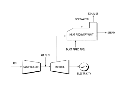
[0008] Figure 1 illustrates a process flow diagram of a typical cogeneration
(electric
power and steam).
[0009] Figure 2 illustrates an embodiment of a Multi-Stage/High Temperature
duct-
fired heat recovery steam generator with two (2) duct burners.
2c
Date recue / Date received 2021-12-03
[0010] Figures 3A and 3B illustrate a thermal profile diagram associated with
using
the embodiment of the Multi-Stage! High Temperature HRSG shown in Figure 2,
with
Figure 3B is an exploded view showing the thermal profile at the pinch point.
Detailed Description
[0011] The following terms will be used throughout the specification and will
have
the following meanings unless otherwise indicated.
[0012] "HRSG" means heat recovery steam generator(s).
[0013] "Duct" refers to a conduit, e.g., for carrying the exhaust gas through
the heat
exchanger tubes of heat recovery steam generators (HRSG).
[0014] "Duct burner" refers to a supplemental burner assembly for HRSG's, with
pipe (duct) sections that produce high flame temperature of about 1700 F to
3000 F,
including thermal radiation. In one embodiment, the duct burner is of a grid-
style to reduce
pressure drop and spread the heat out across the duct, comprising an array of
fuel manifolds
(e.g., openings in the form of nozzles or drilled orifices) to deliver fuel
into the turbine
exhaust stream of the HRSG. The fuel in one embodiment is directed through a
distribution
.. grid of vertical and horizontal sections. Duct burners are known in the
art, e.g., disclosed in
US Patent Publication No. U52014/0099591; US Patent Nos. 3843309; 6453852; and
3830620.
[0015] "Multi-Stage," "multi stage" or "multi-staged" as used in conjunction
with
duct fired, duct burner or duct firing means having a plurality (at least two)
duct burners in
.. series in a HRSG.
[0016] "High Temperature" or "high temperature" when used in conjunction with
duct burner or duct firing refers to having a gas temperature exhaust from any
of the multi-
stage duct burners at a temperature of at least 1600 F.
[0017] -Utility quality gas" refers to gas as available from sources such as
utility
companies, having a HHV (higher heating value) calorific range of at least
1000 BTU/scf, , as
opposed to low BTU sources, e.g., having a HHV calorific range of less than
900 Btu/scf.
[0018] The invention relates to a high efficiency multi-stage duct fired heat
recovery
steam generator (HRSG) to generate steam for use in thermal enhanced oil
recovery (EOR)
applications. The HRSG may be of any type, including natural circulation
HRSGs, forced
.. circulation HRSGs, or once-through HRSGs.
[0019] Once Through Steam Generator: In one embodiment, the HRSG is equipped
with high pressure and temperature tubing (in series or parallel
configurations) to transfer
3
Date recue / Date received 2021-12-03
CA 02894371 2015-06-16
.. heat from gas turbine exhaust and HRSG duct burners into steam, by heating
the feed water
in the high pressure and temperature tubing to a steam quality of at least
65%. The generated
steam has a steam quality of at least 70% in a second embodiment, and at least
75% in a
third embodiment.
[0020] The multi-staged duct fired HRSG has low turbine exhaust gas (TEG)
oxygen
level, e.g., less than 5% in one embodiment; less than 3% in a second
embodiment; and less
than 2% in a third embodiment. The multi-staged duct fired HRSG may be used in
cogeneration or combined cycle applications or modes. In a cogeneration
application, a
compressor coupled to a turbine having a combustion chamber in between,
generates an
exhaust gas. The exhaust gas enters the power turbine and then the HRSG, where
it is used to
.. produce steam. The hot excess air has enough oxygen, e.g., 12 to 15% to
support further
combustion and increase the theinial efficiency of the process to make more
steam with
minimal amounts of fuel, since the air is already hot at >= 1000 F.
[0021] In the inventive multi-stage duct fired HRSG, the available hot oxygen
is
utilized down to 5% or less, for a significant increase in steam production
significantly with
.. very little additional utility fuel gas compared to a single-stage duct
fired HRSG. In one
embodiment, the thermal efficiency of the HRSG is increased to at least 92%.
The thermal
efficiency is maximized with the use of a plurality of duct burners of grid-
style configuration
arranged in series, with each duct burner located upstream of the
corresponding evaporator /
radiant section. In one embodiment, the feed water stream to the evaporators
is split into a
plurality of streams in parallel, one for each duct burner / evaporator
section. The hot exhaust
gas from the turbine (over 1000 F) is directed to the duct burners in series,
allowing further
combustion and maximizing thermal efficiency.
[0022] Duct Burners: The duct burners can be of the same or different
configurations. In one embodiment, at least one of the duct burners has a
rectangular cross-
section and fits into the ductwork carrying the exhaust gases. In another
embodiment, the
duct burner can be of other shapes, e.g., circular shape. In yet another
embodiment, the duct
burner further includes vertical or horizontal fuel gas grids feeding fuel
nozzles for heating
the exhaust gas stream. In one embodiment, each duct burner is an assembly
having a
plurality of gas fired sections arranged in a generally vertical plane within
a case. Each
.. section includes a firing runner pipe that extends transversely through the
easing. Each firing
runner pipe defines a plurality of orifices that open or point generally in
the direction of the
gas turbine exhaust flow. The orifices are configured for discharge of the
combustible gas,
e.g., utility quality gas. Optionally in one embodiment, a flame stabilizer is
provided so that
4
CA 02894371 2015-06-16
when the combustible gas is ignited, the flame stabilizer allows the flame to
be sustained
generally along the runner pipe.
[0023] In certain embodiments, the duct burners may comprise a high-
temperature
material or cladding or coating to withstand high-temperature firing. The duct
burners may
be configured to add heat to the gas turbine exhaust stream.
[0024] The plurality of duct burners (supplemental burners) may be configured
to
burn a variety of different fuels from natural gas to oil. In one embodiment,
the fuel is utility
quality gas in a single duct, and without any supplemental air. The gas flow
begins at the
discharge end of the combustion turbine, flows in a single pass through
various modules (e.g.,
duct burners and corresponding evaporators) in the HRSG and escapes to
atmosphere through
the stack. The exhaust gas is directed to the HRSG modules by its inlet duct.
[0025] Evaporator Sections: The term evaporator may be used interchangeably
with
evaporator / radiant, as the "evaporator" on the steam side can be referred to
as "radiant" on
the combustion side. The multiple duct burners as used in the HRSG are capable
of multi-
stage/high temperature duct firing, with at least one burner for each
evaporator section or
stage. In certain embodiments, there may be two evaporator stages with a
burner for each
stage. In another embodiment, the HRSG has at least three duct burners and
three evaporator
sections.
[0026] The evaporators are heat exchangers, or any type of equipment built for
efficient heat transfer from one medium to another. Evaporator sections are
where the
boiling process or steam generation occurs. As heat energy is absorbed by
water from the gas
stream, the water temperature increases. When water reaches the boiling point
or saturation
temperature, some of the water evaporates or vaporizes to steam. The
evaporator sections can
be any of single-pass, two- and three-row modules. The single pass is on the
water side and is
vertically up. The modules feed a steam/water mixture to the riser pipes. The
modules are fed
with water from the downcomer/feeder header assembly to replace the water
exiting as a
steam/water mixture.
[0027] Economizer: In one embodiment, the HRSG may further include one or more
economizers providing preheated water to the evaporators. Economizer is known
in the art,
which are heat exchange devices that heat fluids, usually water, up to but not
normally
beyond the boiling point of that fluid. In one embodiment, the economizer
sections are
composed of extended or finned tube surface modules. The economizer section
includes
multipass, three-row modules with required drains and vents. These modules are
arranged in
a series/parallel configuration to reach the desired final water temperature
and capacity.
5
CA 02894371 2015-06-16
=
Water flow rate control through the economizer is achieved through the drum
level control
instruments.
[0028] Feed Water Source: The water for use in the HRSG can be any type of
water,
fresh water, waste water, recycled water or water recovered from oil & gas
operations such as
produced water. Produced water from oil recovery operations typically has
relatively high
concentrations of organics, silica, boron, hardness, suspended and dissolved
solids. In one
embodiment, a water treatment unit with one or more water softeners, walnut
filters, ion
exchange units, etc., is provided to purify the water as feed to the HRSG.
[0029] Methods of Operation: Multi-stage duct firing may have any number of
stages, with the turbine exhaust gas temperature showing an increase in
temperature (after
flowing through a duct burner), followed by a decrease in temperature (after
heat transfer
flowing through the evaporator section corresponding to the duct burner),
followed by an
increase in temperature (after the next duct burner in series), followed by a
decrease in
temperature (due to heat transfer to the corresponding evaporator section), so
on and so forth
in subsequent stages with a duct burner and corresponding evaporator section.
For each
stage of duct firing, there is a corresponding decrease in oxygen level of the
exhaust gas,
resulting in an oxygen level in the gas exhausting the stack of 5% or less
depending on the
number of stages.
[0030] The multi-stage duct firing may be configured to use substantially all
available
oxygen in said gas turbine exhaust gas thereby reducing said oxygen levels to
below about
5%, or below about 3% in other embodiments, or below about 2% in yet other
embodiments.
In certain embodiments, no supplemental air is provided to the combustion
process to reduce
oxygen levels in the gas turbine exhaust gas. In other embodiments, negligible
amounts of
supplemental air may be provided to the combustion process to reduce oxygen
levels in the
gas turbine exhaust gas. In one embodiment, the dispersion and distribution of
available
oxygen in the second and subsequent burners (downstream from the first one)
with the use of
perforated plates.
[0031] In operation in one embodiment, the 1st stage duct firing is heated to
a
temperature of at least 1700 F. After heat transfer to the plurality of
evaporator tubes
(evaporator section corresponding to the 1st duct burner), the exhaust gas
temperature is
reduced, e.g., to 600 F. In the subsequent stage duct firing with the
subsequent duct burner in
series, the temperature is brought up, e.g., to at least 1500 F, or at least
1700 F. After the
exhaust gas flows through the 2nd corresponding evaporator section with a
plurality of
evaporator tubes, the temperature is brought back down to at least 800 F. or
at least 500 F, or
6
CA 02894371 2015-06-16
at least 600 F. In one embodiment, the gas turbine exhaust gas is heated in
each of the
subsequent duct burners to at least 1500 F, or at least 1700 F, or at least
2000 F, prior to the
gas entering the evaporator section corresponding to the subsequent duct
burner. The gas
turbine exhaust then enters the economizer section where the gas turbine
exhaust temperature
is further reduced due to heat transfer.
[0032] The configuration of the duct burners and conditions can be effectively
modeled using CFD (computational fluid dynamics). The CFD model can be carried
out
using methods known in the art, with variables including but not limited to
duct geometry;
nozzle location; distribution and sizes of the nozzle(s), distance between
nozzles and
evaporator(s), and distribution devices (if any such as perforated plates and
/ or baffles).
[0033] In one embodiment, the duct burners are configured using a commercially
available software package, e.g., FLUENTTm model, DbCalcTM model, etc., to
specify
minimum duct dimensions and profile plate designs. CFD models may take into
consideration certain variables and / or make certain assumptions regarding
various variables
including but not limited to flow rate of exhaust gas to the burner, minimum
and maximum
exhaust gas temperature to the burner, firing rate, burner head gas pressure
range, burner
head orientation (either horizontal or vertical parallel to exhaust gas flow),
burner head
configuration (straight, H or I arrangements), flame lengths, differential air
pressure range
(across the burner), exhaust gas velocity range to the burner, firing rates
(as BTU/h).
[0034] Depending on the CFD model being utilized, the duct burner output
configuration may include but is not limited to: heat input (BTU/h), burner
length, minimum
duct width and height, profile plate dimension, burner turndown (minimum
achievable heat
input), required pressure drop across the burner, and burner head gas
pressure. In another
embodiment, a CFD model is used using compressible flow relations for flow
cross orifices
in the duct burner to estimate jet penetration and mass flow rate from each
jet of the duct
burner, allowing optimizing the fuel feed pressure, fuel flow rate, metering
hole size, flow
rate of exhaust gas, and duct pressure. In another embodiment, the CFD model
is used to
optimize the metering hole size, number of holes, fuel feed pressure, fuel
mass flow, energy
flow rate, and maximum possible flow.
[0035] CFD modeling of HRSG systems under different scenarios, e.g., comparing
dual duct firing (two duct burners in series) with HRSG systems under any of
simple cycle,
no duct firing, and a single duct burner shows that on the average, the
thermal efficiency
shows an increase of at least 50% over a simple cycle operation, at least 5%
over no duct
firing operation, and at least 3% over a single duct burner operation. In one
embodiment of
7
CA 02894371 2015-06-16
a thermal EOR operation, the use of a dual duct firing allows an increase in
steam generation
rate (as barrels of steam per day or BSPD) of at least 50% over a simple cycle
system; at least
40% over a no duct firing system; and at least 20% over a single duct burner
system.
[0036] Methods for CFD modeling are known in the art, for example, disclosed
in
International Journal of Energy Engineering (IJEE), Jun. 2013, Vol. 3 Iss. 3,
PP. 74-79 ("The
CFD Modeling of Heat Recovery Steam Generator Inlet Duct" by Amen et al.); and
Master
Thesis titled "CFD Modeling of Heat Recovery Steam Generator and its
Components using
Fluent" dated 2006, by Veera Venkata Sunil Kumar Vytl of University of
Kentucky, included
herein by reference in their entirety.
[0037] Figures: Reference will be made to the Figures, showing a various
embodiments of the invention.
[0038] Figure 1 illustrates an exemplary cogeneration process flow diagram of
a
HRSG. Air is compressed in the Gas Turbine (GT) axial compressor ,fuel is
injected into the
GT combustor, and power is generated in the GT Power Turbine which drives the
gas turbine
5, and generates electricity. Gas turbine exhaust gas 6 enters the heat
recovery unit (HRSG)
10 where the exhaust gas 6 is used by the HRSG 10 to convert the feed water
and produce
steam 11 for various applications, including for example heavy oil thermal
enhanced oil
recovery (EOR) production where it is used to reduce viscosity of the heavy
oil.
[0039] Figure 2 illustrates an exemplary embodiment of a Multi-Stage/High
Temperature duct-fired heat recovery steam generator (HRSG) 10, which exhibits
increased
efficiency of at least 92% in producing greater steam volume. As illustrated,
the shaft of the
turbine 5 is connected to an electrical generator 1 which then produces
electrical power. The
waste heat is recovered from the combustion turbine exhaust gas stream by the
HRSG, which
is coupled to the gas turbine 5.
[0040] The HRSG 10 includes multiple evaporator / radiant sections 12,
configured as
heat exchangers. The HRSG is also provided with a plurality of duct burners
14. Utility
quality fuel 2 is provided to the gas turbine 5 and duct burners 14. Each of
duct burners 14
is located upstream of each of the corresponding evaporator / radiant section
12. The duct
burners may be configured to add heat to the gas turbine exhaust stream
received from the
gas turbine, prior to the exhaust stream 17 entering the evaporator sections.
Exhaust gas 17
pressure drop across the duct burners may be relatively low (e.g., ranging
from 0.5 to 10 in.
water column). The HRSG includes an economizer section 16 providing preheated
water to
the evaporators 12. Water source 8 can be fresh water, recovered or treated
produced water.
In operation, energy is extracted from the heated exhaust stream 17 by the
evaporator
8
CA 02894371 2015-06-16
sections 12 to produce steam, which exits the HRSG 10 through steam pipe 18.
In one
embodiment as illustrated, the HRSG is provided with attemporators 19 to
control the
generated steam temperature (with the use of water).
[0041] Figure 3A is a graph illustrating a thermal profile diagram of the
multi-stage
duct firing operation with the HRSG shown in Figure 2. Figure 3B shows the
thermal profile
diagram taking into consideration of process temperature pinch points. Gas
turbine exhaust
at a certain temperature (e.g., >= 1000 degrees F) leaving the gas turbine
enters the HRSG
and is heated with the first duct burners to at least 1500 F, or at least 1700
F, or at least
2000 F, or at least 3000 F. The gas turbine exhaust is heated by the first
duct burner prior to
the gas entering the first evaporator section. Due to heat transfer with the
first evaporator
section, the gas turbine exhaust temperature decreases by a certain amount.
For example, the
temperature may decrease to at least 1000 F, or at least 600 F, or at least
500 F.
[0042] As shown, the 1 st stage duct tiring heated to a temperature of at
least 1700 F.
After heat transfer to the plurality of evaporator tubes (evaporator section
corresponding to
the 1st duct burner), the temperature is reduced, e.g., to 600 F. In the 2"
stage duct firing
.. with the subsequent duct burner in series, the temperature is brought up,
e.g., to 1700 F.
After the exhaust gas flows through the 2" corresponding evaporator section
with a plurality
of evaporator tubes, the temperature is brought back down to at least 800 F.
[0043] In one embodiment, the gas turbine exhaust gas is heated in the second
duct
burner to at least 1500 F, or at least 1700 F, or at least 2000 F, or at least
3000 F, prior to the
.. gas entering the second evaporator section. Again, due to heat transfer
with the second
evaporator section, the gas turbine exhaust temperature again decreases by a
certain amount.
For example, the temperature may decrease to at least 1000 F, or at least 600
F, or at least
500 degrees F. The gas turbine exhaust then enters the economizer section
where the gas
turbine exhaust temperature is further reduced due to heat transfer.
[0044] Advantageously, embodiments disclosed herein arc capable of reducing
oxygen levels in the gas turbine exhaust down below a percentage (by volume)
that greatly
increases steam production efficiency and volume. Embodiments disclosed herein
may be
capable of providing thermal efficiencies of greater than 90%, in some cases
up to 92%.
[0045] Example: The following illustrative example is intended to be non-
limiting.
[0046] Example 1: A CFD was carried out to model an industrial gas turbine
(e.g.,
GE LM2500) implemented as part of a Multi-Stage High Temperature HRSG with
three duct
burners, one burner is upstream of the first tube bundle, and then two re-fire
duct burners.
Assumptions include 59 F / 60% reheat, Oft elevation; combustion of DLN 9 ppm
NOx; the
9
HRSG is single pressure once through sup-fired (1600 F); stack conditions with
5% min. 02
and 180oF minimum temperature; saturated steam at 1690 psig at 80% quality.
[0047] Table 1 shows basic performance calculations generated by the CFD
model.
The HRSG has outlet steam at 75% quality, having <= 2% oxygen in the exhaust
to increase
the thermal efficiency of the cogeneration, and minimize the number of
conventional
OTSG's, operating below the turbine exhaust temperature at each stage. The
static head
provided by the gas turbine is assumed to be 12.00 in-H20 for these
performance runs. In the
illustrative example, the exhaust gas is directed through a duct burner to get
to the maximum
temperature prior to passing over any steam generating surface. The exhaust
gas passes
through steam generating surface to bring its temperature back down to roughly
the original
exhaust temperature of the gas turbine. At this point, the exhaust gas would
begin cycling
between duct burners and the steam generating surface (e.g., the maximum
temperature and
the original exhaust temperature) until 2% 02 is reached. At this point, the
exhaust gas
would pass through additional feedwater pre-heat generating surface
(economizer) until it
reaches the stack temperature. In the table, "duct fired" refers to the first
duct burner prior to
any steam generating surface. The stages refer to the reheating stages
(starting with duct
burner 2).
[0048] Example 2: A model of a HRSG using a GE Frame 7FA gas turbine (steam to
power ratio ranging from 0.53 to 0.89) under different scenarios: simple
cycle, no duct
firing, a single duct burner, and dual duct firing (two duct burners in
series) indicates that the
thermal efficiency would be 38%, 84%, 88%, and 92% respectively, for
corresponding steam
generation rates of 0; 62,000; 98,000 and 164,000 BSPD (barrels of steam per
day)
respectively.
[0049] While the invention has been described with reference to exemplary
embodiments, it will be understood by those skilled in the art that various
changes may be
made and equivalents may be substituted for elements thereof without departing
from the
scope of the invention. In addition, many modifications will be appreciated by
those skilled in
the art to adapt a particular instrument, situation or material to the
teachings of the invention
without departing from the essential scope thereof. Therefore, it is intended
that the invention
not be limited to the particular embodiment disclosed as the best mode
contemplated for
carrying out this invention, but that the invention will include all
embodiments falling within
the scope of the appended claims.
[0050] It is to be expressly understood, however, that each of the figures of
the
citations referenced herein is provided for the purpose of
Date Recue/Date Received 2022-02-24
CA 02894371 2015-06-16
illustration and description only and is not intended as a definition of the
limits of the present
invention.
11
Table 1
Gas Duct-Fired (First
Stage 2 (Second
Turbine Firing) Stage 1 (First
Refiring) Refiring) Total
Once Once
Once
Outlet through through
through Outlet
Cond. Boiler Economizer Boiler Economizer Boiler Economizer Cond.
PERFORMANCE OUTPUT:
Duty MMBtu/hr 91.67 , 70.40 95.02 72.97
167.86 129.69 627.61
Steam Produced lb/hr 178,000 184,500
326,750 689,250
Water Inlet Temp F 523.9 150.0 523.9 _
150.0 525.0 150.0 150.0
Water Outlet Temp 1' F 561.8 523.9 561.8
523.9 561.8 525.0 561.8 ci
Supplementary Fuel
0
Rate lb/hr 13,580.7 7,775.7 8,061.7
7,146.2 36,564.3 t.)
co
t0
Flue Gas Flow Rate 1 lb/hr 715,680 723,456 731,518
738,664 738,664
w
1
-.I
Flue Gas Inlet Temp ' F 59.0 1750.7 1324.1 1749.7
1324.1 1629.6 880.9
ts)
Flue Gas Outlet Temp F 985.0 1324.1 985.0 1324.1
985.0 880.9 246.9 246.9 0
1-,
01
FLUE GAS COMPOSITION (EXIT) _
1
0
Volume Fraction N2 % 76.421% 74.978% 73.538%
72.308% 72.308% 0,
1
1-,
Volume Fraction 02 % 13.495% 9.463% 5.440%
2.001% 2.001% 0,
Volume Fraction CO2 % 3.361% 5.186% 7.007%
8.564% 8.564%
Volume Fraction CO % 0.000% 0.000% 0.000%
0.000% 0.000%
Volume Fraction H2O % 6.723% 10.373% 14.014%
17.127% 17.127%
Volume Fraction SO2 % 0.000% 0.000% 0.000%
0.000% 0.000%
12