Note: Descriptions are shown in the official language in which they were submitted.
CA 02894555 2017-01-20
METHODS FOR DETERMINING GREEN ELECTRODE ELECTRICAL
RESISTIVITY AND METHODS FOR MAKING ELECTRODES
CROSS REFERENCE TO RELATED APPLICATIONS
[0001] This patent application is a non-provisional of and claims priority
to U.S, Patent
Application No. 61/747,742 filed December 31, 2012, and U.S. Patent
Application No.
61/783,933 filed March 14, 2013.
FIELD OF THE INVENTION
[0002] The instant disclosure is directed towards an apparatus and methods
of using the
apparatus in electrode (anode) processing. More specifically, the instant
disclosure is
directed towards an apparatus for measuring the electrical resistivity of a
green form of an
electrode (e.g. anode) and utilizing the green form electrical resistivity to
adjust (if
necessary) the processing parameters of the electrode (e.g. mixing parameters,
anode
composition/pitch content, forming parameters, and combinations thereof).
BACKGROUND
[0003] Electrolytic aluminum production efficiency is influenced by anode
quality.
Testing is conventionally done on baked anodes and is completed on a small
number of the
total anodes produced. Further, testing is often completed long after the
anodes have shipped
to a smelter or are being used in a smelter.
SUMMARY OF THE INVENTION
[0004] Aluminum production efficiency is influenced by anode quality. In
some
embodiments, microstructure variations within anodes (baked anodes and/or
green anodes)
are reflected in the electrical conductivity of the anodes. The instant
disclosure is directed
towards an apparatus configured to measure the electrical resistivity in
electrodes (e.g. green
anodes), in a non-destructive method in order to characterize anodes (e.g.
quality of green
anodes) and/or quantify the impact of the anode production process/process
parameters on
the anode. In some embodiments, properties like density and electrical
resistivity of the
anode (e.g. carbon block) correlate to the underlying microstructure of the
anode. In some
embodiments, variations in electrical resistivity within an anode relates to
processing
parameters including, but not limited to: forming/manufacturing steps,
materials, anode
CA 02894555 2015-06-09
WO 2014/105864 PCT/US2013/077597
composition, or design, In some embodiments, the apparatus, system, and
corresponding
methods are configured to provide measurements of electrical resistivity in
anodes which are
effective at measuring microstructure variations, including for example,
anisotropic
behaviors, the effect of molded forms, and/or the influence of edge areas,
[0005] In some embodiments, the apparatus, system, and methods are
configured to
provide electrical resistivity measurements which cover most of the anode
(e.g. green anode)
volume or surface area (e.g. anode map).
[0006] In one aspect of the instant disclosure, a method is provided. The
method
comprises: determining a measured voltage drop across a green anode surface
via an
electrical resistivity device positioned to contact the green anode surface;
correlating a
measured electrical resistivity from the voltage drop; comparing the measured
electrical
resistivity to a target electrical resistivity; and adjusting (if necessary),
based on the
comparing step, at least one of anode processing parameters. In some
embodiments, based
on the comparing step, no adjustment is made (i.e. the measured value is
within or at the
target value).
[0007] In one embodiment, the adjusting step is selected from the group
consisting of:
changing a pitch to coke ratio; changing a mixing temperature; changing a
mixing time;
changing a mixing RPM; or changing an amount of agitation via mixing; changing
the anode
granulometry; changing one or more of the forming parameters; and combinations
thereof.
[0008] In one embodiment, the adjusting a forming parameter comprises
changing: a
temperature; a cycle time; a pressure applied; a dwell time for pressure
application, a
vibration frequency, a vibration amplitude, a vacuum, a bellows pressure, and
combinations
thereof
[0009] In one embodiment, the correlating, comparing, and adjusting step
are completed
via a specifically programmed computer.
[0010] In one embodiment, the method further comprises indicating a quality
of the green
anode (e.g. high, medium, low) via the measured electrical resistivity. As a
non-limiting
example, using the data obtained with reference to Figure 16, the anodes which
have
electrical resistivity measurements that are the statistical outliers (e.g.
outside the standard
deviation, or 95% confidence levels) having high measured values of electrical
resistivity (as
compared to the statistical mean values for that group) for a group of anodes
manufactured at
a particular pitch wt. % are low quality. In this embodiment, values around
the mean value
for a group of green anodes having a particular pitch content (wt. %) are
medium, and values
2
CA 02894555 2015-06-09
WO 2014/105864 PCT/US2013/077597
below the mean value for a group of green anodes having a particular pitch
content are high.
In one embodiment, when a plurality of electrical resistivity values are taken
on the green
anode, the values are compared to average values for each measurement for
similarly
manufactured green anodes (e.g. having a same wt. % of pitch) and the quality
is quantified
via comparisons of the "anode map" to the mean values or other statistical
metrics,
[0011] In one embodiment, the method further comprises: indicating a green
anode
quality via a specifically designed computer.
[0012] In another aspect of the instant disclosure, a method is provided,
comprising:
mixing a first composition comprising: an amount of coke and an amount of
pitch; forming
a green anode in a mold having the first composition therein; positioning an
electrical
resistivity device about the green anode to define at least one electrical
current path, wherein
the electrical resistivity device comprises: at least two probes adapted to
contact a portion of
the anode surface of the anode and configured to measure the voltage drop
across the current
path; and at least one electrical current source positioned in a spaced
relation from the at
least two probes, wherein the current source is adapted to contact another
portion of the
surface, wherein the current source is configured to transmit an electrical
current from a
current inlet through the anode body to the current outlet; determining a
measured voltage
drop across the green anode surface via the electrical resistivity device;
correlating an
electrical resistivity from the current and the voltage drop across the at
least one electrical
current path; comparing the measured electrical resistivity to a target
electrical resistivity;
and adjusting, based on the comparing step, at least one of the mixing step or
the forming
step,
[0013] In one embodiment, determining comprises: directing a current output
of not
greater than 5 amps from the current inlet to the current outlet.
[0014] In one embodiment, the forming step comprises: pouring the first
composition into
a mold, and pressing the first composition in the mold to form a green anode.
[0015] In one embodiment, the pressing step comprises vibrocompaction,
[0016] In yet another aspect, a method is provided, comprising: mixing a
first
composition comprising: coke and pitch, forming a green anode in a mold having
the first
composition therein; positioning a plurality of electrical resistivity devices
about the green
anode, wherein each electrical resistivity device is configured to contact an
anode surface to
define an electrical current path per each electrical resistivity device,
wherein each electrical
resistivity device comprises: at least two probes adapted to contact a portion
of the anode
3
CA 02894555 2015-06-09
WO 2014/105864 PCT/US2013/077597
surface of the anode and configured to measure the voltage drop across the
current path; and
at least one electrical current source positioned in a spaced relation from
the at least two
probes, wherein the current source is adapted to contact another portion of
the surface,
wherein the current source is configured to transmit an electrical current
from a current inlet
through the anode body to the current outlet; determining a measured voltage
drop across the
anode surface for each electrical resistivity device; correlating an
electrical resistivity from
the current and the voltage drop across the at least one electrical current
path for each
electrical resistivity device; providing an anode map indicative of electrical
resistivity which
is compiled from the measured electrical resistivity measurements for various
portions on
the green anode.
[0017] In one embodiment, positioning comprises: positioning at least four
electrical
resistivity devices onto an anode surface to obtain electrical resistivity
measurements in a
top, bottom, horizontal, and vertical direction along the anode surface,
[0018] In one embodiment, positioning further comprises: positioning at
least one of the
plurality of electrical resistivity devices to provide an electrical
resistivity measurement over
two sides of the green anode via positioning one of the electrical probes and
the current inlet
orthogonally from the other electrical probe and the current outlet.
[0019] In one embodiment, the positioning step is across a corner of the
green anode.
[0020] In one embodiment, the positioning step is across two opposing sides
of the green
anode,
[0021] In one embodiment, the positioning, correlating, determining, and
providing steps
are completed on green anodes in an anode production line,
[0022] In one embodiment, the determining further comprises an electrical
control
system, which is configured to activate each of the plurality of electrical
resistivity devices
sequentially to obtain electrical resistivity measurements for each electrical
resistivity
devices on the green anode.
[0023] In one embodiment, the positioning, correlating, determining, and
providing steps
are performed via a specifically programmed computer configured to be in
electrical
communication with the plurality of electrical resistivity devices.
[0024] In one embodiment, the plurality of measurements are completed
sequentially. In
one embodiment, the plurality of measurements are completed simultaneously by
using
alternating current at different frequencies (wherein each electrical
resistivity devices
4
CA 02894555 2015-06-09
WO 2014/105864 PCT/US2013/077597
comprises a current inlet having a separate AC frequency which is different
from each other
electrical resistivity device's current frequency). In this embodiment, the
simultaneous
measurements are filtered electronically (via one or a plurality of electrical
filters (e.g. one
for each electrical resistivity device) to provide each measured voltage drop
(specific to each
anode portion), which is correlated to an electrical resistivity (specific to
each anode
portion). In some embodiment, the simultaneous measurements are completed and
tracked
with a specifically programmed computer (e.g. which is also in electrical
communication
with the electrical filter).
[0025] In one embodiment, the method comprises: indicating a green anode
quality via
the specifically designed computer.
[0026] In one aspect of the instant disclosure, a method is provided,
comprising:
determining a measured voltage drop across a green anode surface via an
electrical
resistivity device positioned to contact the anode surface; correlating a
measured electrical
resistivity from the voltage drop; comparing the measured electrical
resistivity to a target
electrical resistivity; and adjusting, based on the comparing step, at least
one of anode
processing parameters.
[0027] In another aspect of the instant disclosure, a method is provided,
comprising:
mixing a first composition comprising: coke and pitch (e.g. optionally, anode
butts);
forming a green anode in a mold having the first composition therein;
positioning an
electrical resistivity device about the green anode to define at least one
electrical current
path, wherein the electrical resistivity device comprises: at least two probes
adapted to
contact a portion the anode surface of the anode and configured to measure the
voltage drop
across the current path; and at least one electrical current source positioned
in a spaced
relation from the at least two probes, wherein the current source is adapted
to contact another
portion of the surface, wherein the current source is configured to transmit
an electrical
current from a current inlet through the anode body to the current outlet (AC
or DC);
determining a measured voltage drop across the anode surface; correlating an
electrical
resistivity from the current and the voltage drop (e.g. depends on geometry of
anode and
probe) across the at least one electrical current path; comparing the measured
electrical
resistivity to a target electrical resistivity; and adjusting, based on the
comparing step, at
least one of the mixing step or the forming step.
[0028] In some embodiments, the electrical resistivity device has a current
output of
between 1 Amp and 100 Amps. In some embodiments, the current source provides:
at least
CA 02894555 2015-06-09
WO 2014/105864 PCT/US2013/077597
about 1A; at least about 5A; at least about 10 A; at least about 15A; at least
about 20 A; at
least about 25A; at least about 30A; at least about 35A; at least about 40 A;
at least about 45
A; at least about 50 A; at least about 55 A; at least about 60 A; at least
about 65A; at least
about 70A; at least about 75A; at least about 80A; at least about 85A; at
least about 90A; at
least about 95A; or at least about 100A of current. In some embodiments the
current source
provides over 100A of current.
[0029] In some embodiments, the current source provides: at least about
0.25A; at least
about 0,5A; at least about 0.75 A; at least about 1A; at least about 1.25 A;
at least about
1.5A; at least about 1.75A; at least about 2.0A; at least about 2,25 A; at
least about 2.5 A; at
least about 2.75 A; at least about 3 A; at least about 3.25 A; at least about
3,5A; at least
about 3.75A; at least about 4A; at least about 4.25A; at least about 4.5A; at
least about
4.75A; or at least about 5A of current.
[0030] In some embodiments, the electrical resistivity device has a current
output of
between 1 Amp and 100 Amps. In one embodiment, the current source provides:
not greater
than about 1A; not greater than about 5A; not greater than about 10 A; not
greater than
about 15A; not greater than about 20 A; not greater than about 25A; not
greater than about
30A; not greater than about 35A; not greater than about 40 A; not greater than
about 45 A;
not greater than about 50 A; not greater than about 55 A; not greater than
about 60 A; not
greater than about 65A; not greater than about 70A; not greater than about
75A; not greater
than about 80A; not greater than about 85A; not greater than about 90A; not
greater than
about 95A; or not greater than about 100A.
[0031] In some embodiments, the current source provides: not greater than
about 0.25A;
not greater than about 0.5A; not greater than about 0.75 A; not greater than
about 1A; not
greater than about 1.25 A; not greater than about 1.5A; not greater than about
1,75A; not
greater than about 2.0A; not greater than about 2.25 A; not greater than about
2.5 A; not
greater than about 2.75 A; not greater than about 3 A; not greater than about
3.25 A; not
greater than about 3,5A; not greater than about 3.75A; not greater than about
4A; not greater
than about 4.25A; not greater than about 4.5A; not greater than about 4,75A;
or not greater
than about 5A of current.
[0032] In still another aspect of the instant disclosure, a method is
provided, comprising:
mixing a first composition comprising: coke and pitch forming a green anode in
a mold
having the first composition therein; positioning an electrical resistivity
device about the
green anode to define at least one electrical current path, wherein the
electrical resistivity
6
CA 02894555 2015-06-09
WO 2014/105864 PCT/US2013/077597
device comprises at least two probes adapted to contact a portion the anode
surface of the
anode and configured to measure the voltage drop across the current path; and
at least one
electrical current source positioned in a spaced relation from the at least
two probe, wherein
the current source is adapted to contact another portion of the surface,
wherein the current
source is configured to transmit an electrical current from a current inlet
through the anode
body to the current outlet (AC or DC); determining a measured voltage drop
across the
anode surface; correlating an electrical resistivity from the current and the
voltage drop
(depends on geometry of anode and probe) across the at least one electrical
current path;
comparing the measured electrical resistivity to a target electrical
resistivity; and adjusting,
based on the comparing step, at least one of the mixing step or the forming
step.
[0033] In some embodiments, the forming step comprises pouring the anode
into a mold,
pressing, and/or compaction (e.g. vibrocompaction), In some embodiments, the
forming
step comprises isostatic pressing.
[0034] In some embodiment, the method comprises baking the formed anode.
[0035] In some embodiments, the forming step comprising compacting the anode
mixture
via a vibrocompactor. In some embodiments, the vibrocompactor vibrates to
shake/compact
the anode mixture in a mold.
[0036] In some embodiments, the forming step (e.g, pressing and/or
vibrocompacting)
comprises at least one of: a forming temperature; a cycle time; a pressure
applied; a dwell
time for pressure application (e.g. time of pressure application), vibration
frequency,
vibration amplitude, vacuum, bellows pressure, and combinations thereof.
[0037] In yet another aspect of the instant disclosure, a method is
provided, comprising:
contacting a plurality of probes to a surface of a green anode; directing
current across the
anode body from a first position to a second position; and determining an
electrical
resistivity across a distance on a surface of the green anode (e.g. between
the current input
and outlet).
[0038] In still yet another aspect of the instant disclosure, an apparatus
is provided,
comprising: at least one electrical resistivity device, comprising: at least
two current probes,
configured to contact a surface of a green anode and direct current across the
anode surface;
and at least two electrical probes, placed at a distance from each other and
between the
current probes, wherein the electrical probes are configured to measure a
voltage drop across
the distance of the anode surface; a power source (e.g. a current source - AC
or DC),
configured to supply current to the electrical resistivity device; and at
least one frame,
7
CA 02894555 2015-06-09
WO 2014/105864 PCT/US2013/077597
configured to fit alongside of the anode surface, wherein the frame includes a
plurality of
holes along a length thereof at a predetermined distance from one another,
wherein the holes
are configured to accept and retain at least one of: the current probes and
the electrical
probes.
[0039] In one embodiment, measurements are taken with the electrical
resistivity device
in a sequential manner, wherein the device is configured to first direct a
current from the
inlet to the outlet, then measure the voltage drop with the electrical probes.
[0040] In some embodiments, the measurements with the electrical
resistivity device are
taken in a simultaneous manner, where the current is directed across the anode
surface while
and/or at the same time as the voltage drop is measured by the electrical
probes.
[0041] In some embodiments, the frame comprises an electrical insulation
material and/or
a thermal insulation material. In some embodiments, the frame is configured to
insulate the
probes (e.g. current and/or electrical probes) from each other.
[0042] In some embodiments, the frame comprises at least one anchoring
device,
wherein the anchoring device is configured to retain at least one probe in at
least one hole
and is configured such that the probe applies a threshold pressure (e.g.
contact pressure) to
the surface of the anode.
[0043] In some embodiments, the apparatus comprises: at least 2 electrical
resistivity
devices; at least 3 electrical resistivity devices; at least 4 electrical
resistivity devices, at least
8 electrical resistivity devices, at least 10 electrical resistivity devices,
at least 15 electrical
resistivity devices, or more.
[0044] In some embodiments, the apparatus comprises a plurality of frames,
where the
frames are configured and/or positioned orthogonally to one another. In this
embodiment,
electrical resistivity measurements are taken over a corner of an anode, or on
two sides (e.g.
a top and a bottom, a bottom and a side, and side and a top, or the like).
[0045] In some embodiments, the apparatus is automated such that the
positioning of the
frame(s) and the electrical resistivity device(s) is automatic around at least
some (or all)
anodes in an anode production line.
[0046] In some embodiments, the apparatus comprises an electrical control
system, which
is configured to activate each electrical resistivity device sequentially
(e.g, into separate
measurements),
8
CA 02894555 2015-06-09
WO 2014/105864 PCT/US2013/077597
[0047] In some embodiments, the apparatus comprises a computer in
electrical
communication with the electrical resistivity device and configured to receive
the voltage
drop across the anode surface and correlate an electrical resistivity
measurement(s) and/or
current measurement (e.g. simultaneous with electrical resistivity
measurement), indicative
of the green anode quality.
[0048] In some embodiments, the computer is configured to use a conversion
factor
(sometimes called a calibration factor) for electrical resistivity of the
green anode. In some
embodiments, the conversion factor is based upon at least one of the following
variables,
including but not limited to: the length of the path along the anode surface;
the position of
the path on the anode (e.g. geography on the anode, corner vs. middle) the
current, the
voltage drop, the anode material (e.g. carbon), the anode composition (e.g.
ratio of coke to
pitch, coke granulometry, and spent anode content); and combinations thereof.
[0049] In some embodiments, multiple electrical resistivity measurements
are compiled
via the computer to provide an anode map. In some embodiments, the anode map
indicates
the anode density and/or structure, and is indicative of cracks or
microstructure deviations.
[0050] As used herein, "electrode" means: a conductor (not necessarily
metallic) through
which a current enters or leaves a nonmetallic medium (e.g. a carbon anode, a
green anode,
or an electrolytic cell.) In some embodiments, the electrode is an anode, In
some
embodiments, the electrode is a cathode.
[0051] As used herein, "anode" means: an article intended for use as a
positively charged
electrode in an electrolytic cell (or pot). When used herein, unless otherwise
denoted, anode
refers to green anode. In some embodiments, the anode comprises carbon and is
consumed
by oxygen during electrolysis of non-ferrous metals (e.g. aluminum). In some
embodiments,
the anode comprises an inert composition which emits oxygen during
electrolysis and which
does not substantially degrade/is not consumed to the extent that a carbon
anode is during
the electrolysis process, In various embodiments of the instant disclosure,
the aspects of the
apparatus, systems, and methods are utilizable with various green anode
compositions and/or
green cathode compositions (TiB2, carbon, ceramics, hybrid ceramic/carbon
forms). In some
embodiments, anode refers to a green anode, In some embodiments, anode refers
to a baked
anode (i.e. final monolithic block of carbon, after the green anode is baked).
[0052] As used herein, "green anode" means: an anode formed by mixing and
forming
(e.g. by compressing and/or shaping) the anode composition (e.g. carbon
composition having
coke and pitch or an inert anode composition of cermet, ceramic or metallic
composition)
9
CA 02894555 2015-06-09
WO 2014/105864 PCT/US2013/077597
prior to baking. In some embodiments, a green anode is a formed anode (in the
final anode
form) that is not yet baked. In some embodiments, the final baking step (e.g.
to make a
green anode into a baked anode) is performed to remove volatile components
from the anode
(e.g. from the pitch) and/or decrease the electrical resistivity of the anode,
In some
embodiments, the final baking step transforms the green anode into a baked
anode (e.g. a
monolithic block of coke, monolithic block of ceramic, cermet, or metallic
composition).
[0053] As used herein, "cathode" means: the negative electrode in an
electrolytic cell. In
one embodiment, the cathode is a carbon cathode. In one embodiment, the
cathode is a
ceramic cathode (e.g. titanium diboride). In one embodiment, the cathode is a
hybrid (e.g.
carbon and ceramic materials).
[0054] As used herein, "top" means: the highest point of something,
[0055] As used herein, "stub hole" means: a hole for the anode stub. In
some
embodiments, the stub hole is in the top of the anode.
[0056] As used herein, "anode stub" means: the metal pin which makes
electrical contact
with the anode carbon mass (usually fixed with an iron casting) via the stub
hole.
[0057] As used herein, "bottom" means: the lowest point of something. In
some
embodiments, the anode bottom is the first portion of the anode to touch the
electrolytic bath
of an aluminum electrolysis cell,
[0058] As used herein, "side" means: a surface forming the outside of
something.
[0059] As used herein, "mixing" means: to combine different components
through
blending and/or kneading. In one embodiment, coke and pitch are mixed to form
an
electrode composition (e.g. anode or cathode composition), In one embodiment,
compounds
are mixed to form an green electrode composition having a cermet, ceramic, or
metallic
composition.
[0060] As used herein, "coke" means: an electrical conductor in the green
anode. In
some embodiments, the coke is the carbonaceous residue made from residual fuel
oils
produced in petroleum refining. Some non-limiting examples of coke include:
pet coke,
pitch coke, coke from coal, and combinations thereof.
[0061] As used herein, "pitch" means: an electrical insulator in the green
anode, In some
embodiments, the pitch is a heat-treated tar originating from the coking of
coal, Some non-
limiting examples of pitch include coal tar pitch and petroleum pitch.
CA 02894555 2015-06-09
WO 2014/105864 PCT/US2013/077597
[0062] As used herein, "composition" means: a material formed of two or
more
substances. As one non-limiting example, the anode composition (sometimes
called a
"paste") refers to a material formed from pitch and coke (e.g. with optional
additives and/or
binders). In some embodiments, variations in the composition (e.g. the pitch
to coke ratio)
allows for variations in the green anode (and final baked anode) properties
and
characteristics.
[0063] In some embodiments, increased coke in the coke: pitch ratio allows
for improved
packing of the composition (e.g. higher density, and lower electrical
resistivity of the
resulting anode). In some embodiments, the green anode electrical resistivity
changes with
the amount of pitch used (coke: pitch ratio) in the paste or anode
composition.
[0064] As used herein, "forming" means: to make an object. Some non-
limiting
examples of forming include pressing and vibrocompacting. In one embodiment,
the
electrode composition undergoes a forming step to produce a green
form/electrode. In one
embodiment, the composition is directed into a mold which undergoes a
compacting via a
vibrocompactor.
[0065] As used herein, "pressing" means: to act upon with applied weight or
force. In
some embodiments, pressing conforms the composition to the shape and size of
the green
anode (e.g. via a mold).
[0066] As used herein, a "vibrocompactor" means: a compactor apparatus that
compacts
via a vibrating bench that vibrates the materials together (e.g. in some
embodiments, with the
assistance of a pressing mass on the top of the anode paste).
[0067] As used herein, "vibrating bench" means: a bench that vibrates.
[0068] As used herein, "baking" means to cook (e.g, harden) by application
of heat (e.g.
applied in an oven).
[0069] As used herein, "electrical resistivity device" means: a device for
measuring
electrical resistivity. In one embodiment, an electrical resistivity device
includes a four point
probe (e.g. two voltage probes, two current probes). In one embodiment, an
electrical
resistivity device comprises probes for transmitting and receiving current and
measuring
voltage drop across the material/surface that is electrically connected to the
probes,
[0070] In one embodiment, an electrical resistivity device is used on a
green electrode to
measure the electrical resistivity of the green form. In one embodiment, an
electrical
resistivity device is repositioned within holes of a frame to obtain multiple
measurements
11
CA 02894555 2015-06-09
WO 2014/105864 PCT/US2013/077597
with one electrical resistivity device having different probe placement
around/about the
green electrode surface. In one embodiment, multiple/a plurality of electrical
resistivity
devices are used on a green electrode (i.e, at various positions) to measure
the electrical
resistivity of the green form in multiple positions (e.g. in order to
correlate inhomogeneity of
the electrode).
[0071] As used herein, "voltage drop" means: a decrease in voltage along a
conductor
through which current is flowing. In some embodiments, voltage drops across
green
electrodes are measured and quantified in accordance with various aspects of
the instant
disclosure.
[0072] As used herein, "electrical resistivity" (sometimes called
resistivity or specific
electrical resistance) means: a quantification of how strongly a given
material opposes the
flow of electric current. Electrical resistivity is typically expressed as
Ohm* meter (Srm).
[0073] As used herein, "target electrical resistivity" means: an electrical
resistivity which
is configured for and attributable to a processing parameter indicative of a
characteristic of a
green form (e.g. electrode, anode, or cathode).
[0074] In some embodiments, the target electrical resistivity is a minimum
value for a
given variable (processing parameter or electrode characteristic). In some
embodiments, the
target electrical resistivity is a maximum value for a given processing
parameter (or
characteristic). In some embodiments, the target electrical resistivity is
below a certain
threshold value for a given processing parameter (or characteristic). In some
embodiments,
the target electrical resistivity is above a certain threshold value for a
given processing
parameter (or characteristic). In some embodiments, the target electrical
resistivity is within
a range for a given processing parameter (or characteristic). In some
embodiments, the target
electrical resistivity is outside of a range for a given processing parameter
(or characteristic).
In some embodiments, the electrical resistivity may be a function of a
processing parameter
(or characteristic), and the target electrical resistivity is determined via
observing the trend
line/functional relationship of the resistivity with the parameter or
characteristic of the
electrode,
[0075] As used herein, "probe" means: an object used for making a
connection (e.g.
mechanical or electrical connection).
[0076] As used herein, "voltmeter" means: a meter for measuring voltage.
[0077] As used herein, "current source" means a source for electrical
current, In some
embodiments, the current source is AC. In some embodiments, the current source
is DC.
12
CA 02894555 2015-06-09
WO 2014/105864 PCT/US2013/077597
[0078] As used herein, "computer" means: an electronic device designed to
accept data,
perform operations (e.g. mathematical and logical operations) and provide a
feedback of the
results (e.g. through a display to an operator).
[0079] As used herein, "display" means: a device which shows information.
As a non-
limiting example, the electrical resistivity device is configured with a
computer which has a
display to provide information (e.g. electrical resistivity, referred change
in anode processing
parameters) to an operator or system.
[0080] As used herein, "density" means: the mass per unit volume of an
object. As a non-
limiting example, density refers to a state or quality of compactness in an
anode (e.g. green
anode).
[0081] As used herein, "crack" means: a break or discontinuous region in an
object
without the complete separation of the object into two or more parts. In one
embodiment, the
electrical resistivity device is configured to measure an electrical
resistivity along the
electrode and identify crack(s) in the electrode.
[0082] As used herein, "formation" means: the process of forming something.
In one
embodiment, the electrical resistivity device is configured to measure
electrical resistivity
across multiple locations on an anode (or across multiple anodes) in order to
correlate trends
in the anode production/processing parameters and equipment for the forming
step that
attribute to inhomogeneity of the green anode.
[0083] As used herein, "propagation" means: the act of transmitting
something.
[0084] Without being bound by a particular mechanism or theory, it is
believed that a
"low" resistivity indicates a material that readily allows the movement of
electrical charge.
Along the same lines, a "high" resistivity is believed to indicate a material
that does not
readily allow for the movement of electrical charge.
[0085] In some embodiments, for anodes used in electrolysis, a lower
electrical resistivity
in the anode means that the anode material does not strongly oppose electric
current so the
current is directed into or out of the cell with little resistance, resulting
in more efficient cell
operation. For example an electrode with a low resistivity is a better
conductor of electrical
charge than an electrode with a high resistivity, so in the electrolytic
production of non-
ferrous metal, better conductors provide for a more efficient system (e.g.
lower voltage drop
of the system).
13
CA 02894555 2015-06-09
WO 2014/105864 PCT/US2013/077597
[0086] As used herein, "current density" means: the amount of current
passing through a
given area of a material (e.g. an anode). Current density is typically
expressed as amperes
per square centimeter (A/cm2).
[0087] As used herein, "current efficiency" means: the ratio of the
quantity of metal
produced in the cell by the current passing through compared to that
theoretically expected
from Faraday's Law, but expressed as a percentage.
[0088] As used herein, "current path" means: a path that current follows
through an
object or material.
[0089] As used herein, "aberration" means: an inconsistency in a material
which results
in the departure from the normal course. In some embodiments, cracks or
microstructure
variations in electrodes are aberrations which result in deviations from the
electrical current
flow as it travels through the anode or cathode.
[0090] As used herein, "homogenous" means: having a common property throughout
(e.g. of a uniform nature).
[0091] As used herein, "heterogeneous" means: composed of parts of
different kinds;
having widely dissimilar elements or constituents. In some embodiments (e.g.
at small
length scales about the size of the coke particles), the anodes are
heterogeneous, being made
of coke aggregate and either pitch or pitch coke (i.e. inherent in the anode
composition). In
some embodiments (e.g. at longer length scales) the anodes are heterogeneous
with respect
to the anode average resistivity (or other property) in a region of a certain
size, which varies
from place to place within the anode.) In one embodiment, heterogeneity
(sometimes called
inhomogeneity) is reduced, prevented, and/or eliminated in the green electrode
by aspects of
the instant disclosure.
[0092] Reference will now be made in detail to the accompanying drawings,
which at
least assist in illustrating various pertinent embodiments of the present
invention.
BRIEF DESCRIPTION OF THE DRAWINGS
[0093] Figure 1 depicts a drawing of an electrical resistivity device (e.g,
a four point
probe) used in accordance with the instant disclosure, illustrating the
equivalent electrical
circuit of the probe operation. The resistance (Rs) represents the equivalent
volume
resistance of the material.
[0094] Figure 2 is a schematic representation of the electrical resistivity
device
(comprising four ¨ four point probe assemblies) positioned on an electrode to
obtain various
14
CA 02894555 2015-06-09
WO 2014/105864 PCT/US2013/077597
measurements. "H" depicts the position of probe H, a large horizontal
instrument. "V"
depicts the position of probe V, a large vertical instrument. "T" depicts the
position of probe
T, a small top instrument. "B" depicts the position of probe B, a small bottom
instrument.
[0095] Figure 3A depicts an electrical resistivity device (e.g. four point
probe assembly)
indexed on the flat anode surface.
[0096] Figure 3B depicts the perforated frame (which is configured to hold
the probes at
adjustable, preset distances) and some of the probes.
[0097] Figure 4 depicts the horizontal instrument position (i.e. probe H),
by pattern,
[0098] Figure 5 depicts the vertical instrument position (i.e. probe V), by
pattern,
[0099] Figure 6 depicts the small top and bottom instruments position (i.e.
probe T and
probe B, respectively), by pattern.
[00100] Figure 7 depicts the variability chart for standard deviation by
measurement, for
each probe, on green anodes,
[00101] Figure 8 depicts the variability chart for standard deviation by
measurement, for
each probe, on baked anodes.
[00102] Figure 9 is a graph depicting the correlation of green and baked
anode electrical
resistivity.
[00103] Figure 10 is a table depicting baked vs. green anode comparisons of
electrical
resistivity measurements at different locations along the anodes,
[00104] Figure 11 is a table depicting the coefficient variation of
electrical resistivity
measurements for different locations on baked vs. green anodes.
[00105] Figure 12 is a schematic of an anode manufacturing process.
[00106] Figure 13 is a schematic of an anode manufacturing process in
accordance with
the instant disclosure.
[00107] Figure 14 is a schematic of an anode manufacturing process in
accordance with
the instant disclosure.
[00108] Figure 15 is a schematic of an anode manufacturing process in
accordance with
the instant disclosure.
[00109] Figure 16 is a graph depicting experimental data of the resulting
electrical
resistivity variation in green anode depicted as a function of pitch content
(wt, %).
CA 02894555 2015-06-09
WO 2014/105864 PCT/US2013/077597
[00110] Figure 17 is a graph depicting experimental data depicting the
differences which
result in the green anodes (depicted as small top and small bottom
measurements along an
anode surface), based on differences in the forming parameters (e.g. two
different
vibrocompactors were utilized) as compared to after baking the anodes.
[00111] These and other aspects, advantages, and novel features of the
instant disclosure
are set forth in part in the description that follows and will become apparent
to those skilled
in the art upon examination of the following description and figures, or may
be learned by
practicing the invention.
DETAILED DESCRIPTION
[00112] As the anode is the interface between the energy source and the
reaction cell, the
energy consumed by passing the electrical current through the anode block is
basically a
loss, as it does not contribute to the reduction of the alumina in the
electrolysis cell. In one
embodiment, the apparatus, system, and methods of the instant disclosure are
directed
towards utilizing an electrical resistivity device on a green form of an
electrode in order to
(1) determine the quality of the electrode (e.g. quality of high, medium, low,
or pass/no pass;
identify underlying inhomogeneities/inconsistencies in the electrode
structure) and/or (2)
impact the processing parameters for electrode production (e.g. composition,
mixing
parameters, forming parameters, and possible downstream baking parameters).
[00113] Without being bound to a particular mechanism or theory, it is
believed that the
green electrodes (prebaked carbon anodes or cathodes) obey Ohm's law; thus, a
lower
intrinsic electrical resistivity of the carbon in the anode block will result
in an overall lower
electrical resistance of the anode. Through one or more of the aspects of the
instant
disclosure, measurements of the electrical resistivity of the green anodes are
made, which
provides feedback as to whether there are any internal inconsistencies (e.g.
inhomogeneity,
cracks, voids, inclusions, inferior degree of coke packing (e.g. lower packing
density)) and
also provide feedback as to the electrical resistivity of the resulting
(baked) anode.
[00114] In one embodiment, an electrical resistivity device/apparatus is
used to measure
green anode electrical resistivity and adjust manufacturing parameters in line
in order to
produce improved anodes (e.g. increased homogeneity). In some embodiments, one
or more
of the aspects of the instant disclosure are used to determine the optimum
green anode
electrical resistivity which corresponds to the highest baked anode density
and/or lowest
baked anode electrical resistivity. One or more embodiments of the instant
disclosure
16
CA 02894555 2015-06-09
WO 2014/105864 PCT/US2013/077597
provide an effective way to maintain process control of green anode
manufacturing and
resulting quality control of the final baked anodes.
Example 1: Electrical Resistivity Device & General Methodology
[00115] Referring to Figure 1, a device for measuring the electrical
resistivity in a surface
of an electrode (e,g, anode) is provided. Figure 1 provides a drawing of the
equivalent
electrical circuit of the device in operation, where the resistance (Rs)
represents the
equivalent volume resistance of the material. As shown in Figure 1, as the two
outer current
carrying probes are placed on the flat anode surface area, an electric
potential distribution is
generated within the electrode (e.g. carbon material) volume and surface. The
electric
current travels through the electrode body to complete the electrical circuit,
The two outside
tips (current probes) force current across the material from a source (AC or
DC). Then, a
reading of the voltage drop is measured by the two middle tips (electrical
probes). Without
being bound by a particular mechanism or theory, because the voltmeter
resistance is much
higher than the material resistance (e=g, carbon), it is assumed that all the
current goes
through the material meaning that the current (0 is the same all around the
exterior wire and
equal to zero across the voltmeter (4=0). For the experiments discussed under
Example 1,
the current probes are spaced apart from each other by 72.5 mm and the
electrical probes are
spaced apart from each other by 51.5 mm.
[00116] Without being bound to a particular mechanism or theory, there is a
linear
relationship between the voltage drop measured between the two inner probes
and the
electrical resistivity of the tested material. The later can be inferred from
the voltage drop
using a calibration factor, f . This factor in turn, will depend on other
factors like the
distance between the probes, geometry of the carbon block, shape of the
probe's contact
pads and relative position of the probes to the block geometry.
[00117] This relationship can be written as follows:
V
P=
I * f
Where p is the electrical resistivity, f is the above mentioned calibration
factor, V is the
voltage drop measured and / is the electric current applied.
17
CA 02894555 2015-06-09
WO 2014/105864 PCT/US2013/077597
[00118] For the same anode geometry and identical measurement location, the
factor f
used was the same for all the measurements, regardless of the presence of any
internal flaws.
Without being bound to any particular mechanism or theory, it is believed that
for any
internal discontinuity that may alter the length of the electric current path,
or which may
change the cross section of the volume travelled by the electric current,
changing the electric
potential distribution, the corresponding change in voltage drop will be
interpreted as a
change in the intrinsic electrical resistivity of the electrode material (e.g.
carbon). Without
being bound by a particular mechanism or theory, it is expected that changes
that impact the
electrical resistance of the block will be exposed by this measurement as an
electrical
resistivity change, without having the capability to discern whether the
change is an intrinsic
resistivity change, as it would be expected from a different level of
graphitization of the
carbon material, or is an internal discontinuity problem.
[00119] Electrical resistivity measurements were taken on both baked anodes
and green
anodes. In one embodiment, the green anode block is heterogeneous, composed of
calcined
coke, an electrical conductive material, and pitch, an electrical insulator.
Without being
bound to a particular mechanism or theory, the electrical conductivity of the
green block,
even if very poor, can reflect the quality and the number of the points of
contact between the
coke particles. Therefore, this measurement can detect the presence of cracks
and micro-
cracks, the degree of particles packing and the variation in pitch coating of
the coke
particles.
Example 1 Four Electrical Resistivity Devices (4-4 point probes)
[00120] An assembly of four devices was designed and held together rigidly
by a larger
frame. The frame offered the possibility to index the measurement's location
relative to the
anode surface via a plurality of holes at a predetermined distance along the
frame body (i.e.
which followed along the anode surface). A schematic representation of the
location of the
four instruments relative to an anode is depicted in Figure 2. Referring to
Figure 2, H refers
to the large horizontal instrument, V refers to the large vertical instrument,
T refers to the
small top instrument, and B refers to the small bottom instrument.
[00121] Figure 3A depicts the four electrical resistivity devices held via
the frame
assembly over an anode. Referring to Figures 3A and 3B, the frame was
perforated such
that the respective probes' position/orientation was adjustable in one inch
increments, such
that even with adjustment, the probes maintained their horizontal or vertical
orientation,
respectively. Figure 3A depicts the general assembly, while Figure 3B is a
close-up
18
CA 02894555 2015-06-09
WO 2014/105864
PCT/US2013/077597
perspective side view the frame and some of the probes. The two larger
instruments use
separate DC power sources, capable of an output of 75A. The smaller probes,
share a DC
power capable of an output of 20A. Each power source has an individual on/off
switch,
allowing for the measurements to be taken successively, one instrument being
active at a
time.
[00122] Some of the faCtors used for the examples herein are presented in
the table below.
[00123] Table I: Probe location, modeled voltage drop and calibration
factor.
Position Probe-to-Shoulder Probe-to-Edge Probe-to-Shouldei Probe-to-Edge
nVolts(5 A, 2000 S/m Calibration
Horizontal Probe: (m) (m) (in) (in)
1 0.18415 0,04445 7,25 1,75 42.196 16878
2 0.0508 0.04445 2 1,75 44.984 17994
3 0.3556 0.04445 14 1.75 45.893 18357
Vertical Probe
1 0.01905 0.6858 0.75 27 19.71 7884
2 0,01905 1,0858 0.75 42.75 19,071 7628
3 0,0762 0.4572 3 18 19,162 7665
4 0.0762 0,2667 3 10.5 19.456 7782
0.0762 1.289 3 50.75 19.482 7793
Small Probe-Top
1 0,01905 0.22225 0.75 8.75 32,231 12892
2 0.01905 0.70485 0,75 27.75 32,252 12901
3 0,0762 1,1176 3 44 31,665 12666
4 0.0762 1,5367 3 60,5 50.017 20007
5 0.0762 0.01905 3 0.75 41.13 16452
Small Probe - Bottom
1 0,2286 0.22225 9 8,75 31.564 12626
2 0.2286 0.70485 9 27,75 31,462 12585
3 0,28575 1.1176 11,25 44 31,583 12633
4 0.28575 1.5367 11.25 60.5 49.945 19978
5 0,28575 0,01905 11,25 0,75 41.009 16404
Example 3: Measurements on Green Anodes and Baked Anodes
[00124] A study was completed on site at an anode manufacturing plant.
Approximately
2400 measurements were taken, on full size anodes. One set of three
measurements was
taken on 11 baked anodes and on 11 green anodes, randomly picked from an anode
inventory, which were considered to be representative.
[00125] The assembly of Example 2 was first indexed on the anode side and
one
measurement was taken. The second measurement was a repeat measurement,
changing
19
CA 02894555 2015-06-09
WO 2014/105864 PCT/US2013/077597
nothing. For the third measurement, the assembly was detached from the anode
surface, and
reset in the same location, using the indexing devices as guidance, making
sure that the
measurement is taken in the same location. At a later time, a new set of three
measurements
was taken on the same anodes. Again the frame was indexed to the anode surface
such that
the measurement would be taken in the same location as previously. The three
measurements were taken as the ones in the first set, with one exception.
After detaching the
frame from the anode surface, for the third measurement, the frame was
intentionally
repositioned with a shift of approximately 0.5 inches from the previous
location.
[00126] After completing the above measurements the relative position of
the instruments
to the anode surface was changed, by assembling the four instruments in a
different pattern.
A total of five different patterns were used, and for each pattern all the
above described
measurements were taken again on both, green and baked anodes. The positions
of the four
point probe instruments relative to the anode surface are shown in Figures 4,
5 and 6.
[00127] Given the anode geometry, five different locations for the vertical
instruments
were included in the experiment, whereas for the horizontal instrument only
three locations
were considered. Details regarding the distance between the probes and the
electric current
used for each probe, on both green and baked anodes are presented in the Table
IT below.
[00128] Table II: Instruments' geometry and electric current used for both
anode types
Probe Distance Distance Green anode Baked anode
between between current I (A) current I (A)
current potential
points points
Horizontal 56" 54" 5 20
Vertical 12" 9 5 __________ 20
Small top 3.75" 2.25" 5 20
Small bottom 3.75" 2.25" 5 20
[00129] All the voltage drop measurements were converted into electrical
resistivity
values, using the correction factors detailed above. These values were used to
estimate the
variance components of the measurements. Without being bound to a particular
mechanism
or theory, it was assumed that the four point probe instrument precision can
be characterized
by measurement standard deviation ranking. This analysis was performed by
using the
statistical software JMP. The standard deviations associated with the repeat,
reset and
CA 02894555 2015-06-09
WO 2014/105864 PCT/US2013/077597
pattern measurements (described above) are presented in Figure 7 for the green
anodes and
Figure 8 for the baked anodes. In addition, the anode standard deviation is
also shown in
these plots, which basically characterizes the variability between the anodes
and is calculated
as the standard deviation of the per anode means (all measurements included).
[00130] It is noted that the anode variation and the pattern variation
compete as the largest
source of variation, depending on probe and anode states, baked vs. green.
There is one
exception to this, the small top instrument measurements on baked anodes,
Reset and
repeatability standard deviations are low relative to the other sources.
Without being bound
to a particular mechanism or theory, this indicates that the instruments can
be used to detect
within the anode and between anodes differences due to assignable causes. In
addition, the
larger probes, H and V, show lower reset and repeatability variation than the
smaller
instruments, T and B. Without being bound to a particular mechanism or theory,
due to the
believed heterogeneity of the anodes, this result was expected.
Example 4: Comparison of Core Instrument to Instrument of Example 2
[00131] In this example, the standardized measurement's precision on
measuring electrical
resistivity of baked cores was compared to the precision of the device of
Example 2. In order
to do this, the total test errors were calculated, This was computed as the
statistical sum of
the repeatability and reproducibility. In one embodiment, for a possible in-
line automated
measurement system, the reproducibility term is calculated from measurements
taken at the
same location within short order, with the instrument pulled back, then re-
positioned onto
the same anode, This is basically setup reproducibility, and the customary
measurement of
the same material by a different operator using a different instrument has
little relevance for
this application. Based on the above, the total test errors have been
calculated and the results
are presented in Table III.
21
CA 02894555 2015-06-09
WO 2014/105864 PCT/US2013/077597
Table III: Total test error and coefficient of variation, by probe.
Probe Repeatability Reproducibility
Total test LSD Median resistance CV
error
Baked Anode Measurements
Horizontal 0.27 0.85 0.9 1.8 53.93
1.7
Vertical 0.37 0.76 0.8 1.7 54.14
1.6
Small Top 1.09 2.16 2.4 4.8 39.71
6.1
Small Bottom 0.84 2.06 2.2 4.4 42.91
5.2
Std. Core Inst. 1.2 1.5 1.9 3.8
Green Anode Measurements
Horizontal 6.29 17.76 18.8 37.7 1997.33
0.9
Vertical 11.58 17.53 21.0 42.0 2004.36
1.0
Small Top 20.11 70.33 73.1 146.3 1551.82
4.7
Small Bottom 25.39 82.2 86.0 172.1 1760.47
4.9
[00132] The total test error for the two larger probes (H, V) appears to be
roughly half of
that of the standard core instrument. The smaller probes (T, B) show a
slightly inferior test
error. Without being bound to a particular mechanism or theory, one
explanation is that
these measurements were taken manually, and may have lacked a consistent
pressure on the
contact points. Thus, based on this comparison, it is expected that even the
smaller probes
are going to be at least as good as the current standard core measurement
instrument from a
precision point of view.
[00133] For measurements on the green anode there is no standardized method
for
reference. Instead, calculating the coefficient of variability, CV, a direct
comparison between
the precision of these instruments on the two different anode states can be
made. The CV
values for the measurements on both, green and baked anodes are also presented
in Table
It can be seen that the measurement precision on the green anodes is superior
to the precision
on the baked anodes. The calculation of the least significant difference, LSD,
is also
provided in Table III, and will be useful in analyzing differences between
anodes in future
designs of experiment.
[00134] These electrical resistivity measurements were plotted and it was
determined that
the patterns appeared to be random in comparing anode-to-anode. Thus, at least
for the 22
22
CA 02894555 2015-06-09
WO 2014/105864 PCT/US2013/077597
anodes tested, there was no pattern revealed regarding a consistent anode
electrical
resistivity print based on the anodes being from the same manufacturing
line/location.
Example 5: Baked and Green Anode Electrical Resistivity Measurements
[00135] At an anode manufacturing location, measurements were taken on 30
baked
anodes and 10 green anodes using an electrical resistivity device as set forth
in Example 1. It
was determined that the response of the four point probe depends upon the
geometry of the
surface to which it is applied. If the surface is generally concave, the
measured voltage drop
will be higher than for a flat surface, and vice-versa. Consequently, a
geometry-specific
correction factor is needed to properly calculate the resistivity from the
measured voltage.
The correction factor was approximated for each measurement location using
finite element
simulation of the measurement procedure.
[00136] Without being bound to a particular mechanism or theory, it appears
that fairly
good correlations exist between the two, although the results should be
grouped: the
correlation near the stub-hole is different from that on the sides and ends of
the anodes. This
is more clearly shown in Figure 9. Figure 10 depicts the resistivity for both
the baked and
green anodes. Figure 11 depicts the coefficient of variation for the baked and
green anode
measurements. Referring to Figure 11, the CV is higher for the green anode
measurements.
Without being bound to a particular mechanism or theory, this was expected as
the pitch is
essentially non-conductive, so that in the green anodes, conductivity was
limited to contacts
between the coke particles. Thus, it is believed that measuring the electrical
resistivity in the
green anodes will provide a more sensitive measure of the structural
variations brought about
by the anode manufacturing process. One source of possible error in these
measurements of
Figure 10 and 11 is the manual indexing of these small scale measurements may
have
resulted in a lower overall precision, or a calculation error may have
resulted from a
typographical error with the current amperage of the green anodes.
Example 6: Electrical Resistivity as a Function of Pitch Content in Anode
Composition
[00137] Referring to Figure 16, a number of measurements have been
conducted on green
anodes (carbon material), with pitch as the only variable. The pitch variation
was limited to
0.1% increments. These tests were completed on different days, and using
different dry
aggregate recipes. Each anode was measured in eight different locations with
electrical
resistivity devices retained in different locations with an electrically
insulated frame. For
each location, the electrical resistivity measurement generated a curve as the
one shown in
Figure 16. For each curve, the minimum electrical resistivity measurement was
at or very
23
CA 02894555 2015-06-09
WO 2014/105864 PCT/US2013/077597
close to the optimum pitch level in anodes. The obtained curves for each
series of
measurements were approximately parallel. However, the electrical resistivity
values
(absolute values), including the minimums, were different. Without being bound
by a
particular mechanism or theory, this is believed to be based on some factors,
including:
measurement location and recipe used for each anode. Without being bound by a
particular
mechanism or theory, these findings are indicative that in-line electrical
resistivity
measurements on green anodes provide a useful feedback to the process with
respect to
varying the anode composition (i.e. changing the pitch to coke ratio to
optimize pitch content
in an anode composition for a given anode production process).
Example 7: Heterogeneity Measurements on Green Anodes
[00138] Referring to Figure 17, a series of electrical resistivity
measurements were taken
on green anodes after forming (i.e. where forming was vibocompaction on one of
two
vibrocompactors) and after baking. Electrical resistivity measurements were
taken along a
top and bottom of the long side of each green anode in order to evaluate anode
heterogeneity
due to vibrocompaction and to observe how baking impacted the electrical
resistivity
measurements. Though some anodes were tracked through the process (i.e. after
forming the
green anode through baking to form the final, baked anode), a number of anodes
were not
sufficiently tracked through the process, which resulted in a larger sample
size of green
anodes after forming than the sample size for baked anodes after baking.
[00139] The graphs depicted in Figure 17 illustrate the anode heterogeneity
in the forming
process and after the baking process, as exposed by the electrical resistivity
measurements
(all measurements in IA Qm). With reference to Figure 17, it is noted that all
four top
measurements are smaller than any of the four bottom measurements. Also, it is
noted that
all of the electrical resistivity measurements on compactor #1 are smaller
than the equivalent
ones on compactor #2. For the baked anodes, the differences are not
significant.
[00140] All four measurements taken at the top of the anode (T), two on the
green anodes
and two on the baked ones, are smaller than any of their respective bottom
measurements,
regardless of the compactor on which the anodes were produced. Without being
bound by a
particular mechanism or theory, this may be attributable to the forming
process (e.g. friction
with the mold, unequal compaction, etc). The distribution and the simple
statistics of all
these measurements are presented in Figure 17.
[00141] Also, it is noted that all the measurements taken on the anodes
made on compactor
#1 are smaller than the equivalent measurements taken on compactor #2.
However, this
24
CA 02894555 2015-06-09
WO 2014/105864 PCT/US2013/077597
difference is not as observable in the baked anodes, and was confirmed that
the difference is
not statistically different. Without being bound by a particular mechanism or
theory, the
electrical resistivity measurements resulted in top to bottom differences
which are believed
to be compactor dependent. Also, Figure 17 is confirmation via electrical
resistivity
measurements in that the baking process appears to reduce: the differences in
electrical
resistivity between the top and the bottom, as well as the differences
resulted from the
compaction on the two different compactors.
Prophetic Example: Method of Optimizing Pitch via Electrical Resistivity
[00142] In one embodiment, a method is provided for making green anodes,
where the
electrical resistivity measurements are utilized in order to optimize the
amount of pitch in the
anode composition (e.g. pitch to coke).
[00143] The method provides: forming a first green anode from an anode
composition
having a first pitch content, the first anode having a first electrical
resistivity; forming a
second green anode, the anode composition having a second pitch, the second
anode having
a second electrical resistivity, where the second pitch is different than the
first pitch (e.g.
higher or lower pitch wt. %), and obtaining the first electrical resistivity
and the second
electrical resistivity (e.g. from a measured voltage drop from which the
measured electrical
resistivity is measured); and comparing the first electric resistivity to the
second resistivity.
[00144] In some embodiments, if the first electrical resistivity is lower
than the second
electrical resistivity, revert to the first pitch content of the anode
composition.
[00145] In some embodiments, if the first electrical resistivity is lower
than the second
electrical resistivity, the method comprises forming a third green anode, the
anode
composition having a third pitch, the third anode having a third electrical
resistivity, where
the third pitch is different from the first pitch and closer to the first
pitch wt. % than the
second pitch wt. %, and reiterate the previous steps, but for this variation
(i.e. obtaining
resistivities, and comparing the resistivities as set out above, to generate
an action ¨ change
pitch (increase or decrease) or maintain pitch).
[00146] In some embodiments, if the first electrical resistivity is higher
than the second
electrical resistivity, revert to the second pitch content (wt. %) of the
anode composition.
[00147] In some embodiments, if the first electrical resistivity is higher
than the second
electrical resistivity, the method comprises forming a fourth green anode, the
anode
composition having a fourth pitch, the fourth anode having a fourth electrical
resistivity,
where the fourth pitch is different from the second pitch and is closer to the
second pitch
CA 02894555 2015-06-09
WO 2014/105864 PCT/US2013/077597
than the first pitch wt, %, and reiterate the previous steps, but for this
variation (i.e. obtaining
resistivities, and comparing the resistivities as set out above, to generate
an action ¨ change
pitch (increase or decrease) or maintain pitch).
[00148] It is noted that while first, second, and third anodes are called
out above, first
anode is also understood to refer to a first group of anodes (second anode as
second group of
anodes, third anode as third group of anodes, fourth anode as fourth group of
anodes, and so
on), with the electrical resistivity measurements referring to a statistical
summary of the
same for the corresponding group (e.g. mean value, mean square value, median
value, etc.).
[00149] In some embodiments, the second pitch is higher than the first
pitch, so the third
pitch is selected to be lower than the first pitch. In some embodiments, the
second pitch is
lower than the first pitch, so the third pitch is selected to be higher than
the first pitch, Based
on the trend depicted in Figure 16, an iterative change in pitch content
(followed by wt. %)
and electrical resistivity measurement can be used to determine the optimum
pitch for an
anode production process operation, for that particular formulation, equipment
set up, and
anode composition (e.g. butt content, percent of volatiles in the pitch, %
granulometry, etc,).
Prophetic Example: Method of Monitoring of Anodes and Adjusting Anode
Production
Process
[00150] In one embodiment, electrical resistivity measurements are taken
from anodes at
least one of various locations along the anode production process. In one
embodiment,
electrical resistivity measurements are taken on each (or a group of) green
anodes
immediately after forming (while still hot from forming process). In one
embodiment,
electrical resistivity measurements are taken on each (or a group of) green
anodes
immediately after cool down from the forming step,
[00151] In some embodiments, if the electrical resistivity of the green
anodes are within
the target electrical resistivity (e.g. at the minimum, at the maximum, below
a certain
threshold, above a certain threshold, within a range, outside of a range, or a
combination
thereof), no adjustment is needed (e.g. such that in lieu of adjusting, the
method comprises a
repeat step to continue determining electrical resistivity and continue
correlating the same
against the target electrical resistivity to monitor whether an adjustment is
needed).
[00152] In some embodiments, each anode (green or baked) is lifted from the
production
line via a stand (e,g, made of electrically insulated materials) and
configured to measure the
electrical resistivity via an electrical resistivity device or permit such
device(s) with
accompanying frame to measure the same. In some embodiments, the frame is
adjustable. In
26
CA 02894555 2015-06-09
WO 2014/105864 PCT/US2013/077597
some embodiments, the frame is rigid. In some embodiments, each anode (green
or baked) is
rolled onto electrically insulated materials (e.g. plastic rollers, non-
conductive rollers) that
are located in-line in order to obtain electrical resistivity measurements.
[00153] Referring to Figure 12, an exemplary flow path of anode production
is depicted.
Referring to Figure 12, coke is crushed and sized into the appropriate size
fraction(s). Some
recipes for the anode composition call for various sized fractions (e.g.
course, intermediate,
fine, extra-fine), some for two or more (e.g. three, four) different size
fractions of coke,
[00154] After the coke is crushed and sized, the anode composition is
mixed, with a ratio
of coke to pitch. The ratio of coke to pitch (and/or binder content) impacts
the resulting
anode quality. In some embodiments, the composition includes: coke and pitch
(either coal
tar or petroleum pitch, or a mix); and/or optional additives. Some non-
limiting examples of
additives include: paste scrap, or green anode scrap, recycled crushed used
anodes, also
known as anode butts, and combinations thereof. The composition (first
composition) is
mixed to combine or blend the components. Non-limiting examples of mixing
include:
mechanical stirrers, shaking the vessel holding the composition, or other
stirring mechanisms
to combine the components. In some embodiments, depending on the ratio of coke
to pitch,
the mixing energy (frequency, mixing time, etc) is adjusted (increased or
decreased) such
that the resulting mixture is blended (e.g. homogeneously),
[00155] After the composition is mixed, a green anode is formed from the
composition. As
some non-limiting examples for forming, the green anode can be pressed or
vibrocompacted
into the green anode form. In some embodiments, the vibrocompactor includes
additional
components which are configured to apply pressure to certain parts of the
compactor,
[00156] Once the green anode is formed, the resulting green anode is baked
(e.g. in an
oven) in order transform the green anode of a first composition into a
monolithic block of
coke. In some embodiments, the baking step removes volatile components present
in the
green anode and further densifies the anode components (e.g. increasing the
real density,
reducing the electrical resistivity).
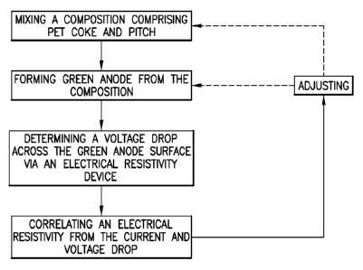
[00157] Referring to Figure 13, a method is depicted, comprising: mixing a
composition
comprising coke and pitch; forming a green anode from the composition;
measuring one or
more voltage drop across the green anode surface via an electrical resistivity
device; and
correlating one or more electrical resistivities from the current and voltage
drop.
[00158] Referring to Figure 14, a method is depicted, comprising: crushing
and sizing the
coke; mixing a composition comprising coke and pitch; forming a green anode
from the
27
CA 02894555 2015-06-09
WO 2014/105864 PCT/US2013/077597
composition; positioning an electrical resistivity device about the green
anode (e.g. along the
surface of the green anode to define at least one electrical current path);
directing current
across the anode surface between two current probes of the device; and
measuring one or
more voltage drop(s) across the anode surface via two electrical probes (e.g.
wherein the
electrical probes are located between the current probes and in spaced
relation from each
other); and correlating one or more electrical resistivities from the current
and voltage drop.
In some embodiments, the anode surface comprises a top, a bottom, a side,
across a corner,
across a stub hole, inside of a stub hole (e.g. in the flutes, or internal
ridges of the stub hole,
and/or the depressions in the stub hole), etc.
[00159] Referring to Figure 15, in some embodiments, one or more of the
aforementioned
methods include the step of comparing the measured electrical resistivity to a
target
electrical resistivity. In some embodiments, one or more of the aforementioned
methods
comprise the step of adjusting, based on the comparing step, at least one of
the anode
production parameters: e.g. the mixing step or the forming step.
[00160] In one embodiment, adjusting comprises changing the coke to pitch
ratio. In one
embodiment, the adjusting step comprises increasing the amount of coke
relative to the
amount of pitch in the composition (e.g. a second composition, which is
different than the
first composition). In one embodiment, the adjusting step comprises decreasing
the amount
of coke relative to the amount of pitch in the composition (e.g. a second
composition, which
is different than the first composition).
[00161] In one embodiment, the adjusting step comprises increasing the
mixing time,
mixing rpm (e.g. with a stirrer or stir bar), or amount of agitation via
mixing.
[00162] In one embodiment, the adjusting step comprises changing the anode
granulometry (e.g. changing the ratio of coke fractions, including the amount
of coarse, fine,
and/or super fine materials).
[00163] In some embodiments, the adjusting step comprises: changing one or
more of the
forming parameters; increasing the pressure during the forming (e.g. pressing)
step;
decreasing the pressure during the forming (e.g. pressing) step; increasing
the dwell time
during the forming step; decreasing the dwell time during the forming step;
increasing the
number of pressing cycles; decreasing the number of pressing cycles;
increasing the
vibration frequency of the vibrocompactor; decreasing the vibration frequency
of the
vibrocompactor; and combinations thereof.
28
CA 02894555 2015-06-09
WO 2014/105864 PCT/US2013/077597
[00164] In some embodiments, based on the comparing step, the method
comprises,
setting a baking step in accordance with the green anode resistivity. In some
embodiments,
the baking step comprises: increasing the bake time, decreasing the bake time,
increasing the
bake temperature, decreasing the bake temperature, or positioning the green
anode
differently within the oven (e.g. different heat flux at center vs. ends of
oven) in accordance
with the green anode resistivity measurement in order to provide a final baked
anode with a
desired electrical resistivity and density,
[00165] In some embodiments, for one or more of the aforementioned methods,
one or
more of the crushing and sizing; mixing; forming; positioning; measuring;
correlating;
comparing; and adjusting steps are completed in an automated manner (e.g. via
a feedback
loop on a computer and an automated assembly line of an anode manufacturing
process).
[00166] As detailed herein, in some embodiments, a specifically designed
computer is
configured to receive multiple electrical resistivity measurements from a
green electrode
(e.g. anode) and incorporate the measurements in order to provide an anode map
(e.g.
depicting inhomogeneities) indicative of the anode quality (high, medium, low,
pass/no
pass).
[00167] In some embodiments, a specifically designed computer is configured
to monitor
(monitoring) an anode production process by comparing electrical resistivity
measurement(s)
obtained for each anode (or group of anodes) in a production process (e.g.
after forming
green anode while still warm, after cooling the green anode as it exits from
the forming
process, and/or after baking to transform the green form into the final, baked
anode), and if
the measured electrical resistivity values are not within the target
electrical resistivity values,
adjust the production process (e.g. adjust the anode processing parameters:
anode
composition, anode mixing process, anode forming process, or anode baking
process). In
some embodiments, the specifically programmed computer operates in a
continuous, real-
time process monitoring and adjusting, if necessary, the anode production
process. In some
embodiments, the specifically programmed computer operates in a periodic, real-
time
process in monitoring and adjusting, if necessary, the anode production
process. In some
embodiments, the specifically designed computer is configured to
monitor/review historical
anode data (e.g. electrical resistivity measurements) in order to identify
equipment to be
serviced and/or replaced, or to evaluate operator performance. In some
embodiments, the
specifically designed computer is configured to correlate performance data of
the final baked
anodes with the data for the anodes produced in a particular production line
to identify
29
CA 02894555 2015-06-09
WO 2014/105864 PCT/US2013/077597
additional improvements and/or variables in processing parameters and anode
characteristics.
[00168]
Computer architecture: The inventive computer methods and the computer
systems/machines of the instant invention utilize various computer machines.
However, not
all of these computer machines may be required to practice the invention, and
variations in
the arrangement and type of the components may be made without departing from
the spirit
or scope of the invention. In some embodiment, the computer systems/machines
of the
instant invention host a large number of members and concurrent transactions.
In other
embodiments, the computer systems/machines of the instant invention are based
on scalable
computer and network architectures that incorporate varies strategies for
assessing the data,
caching, searching, and database connection pooling.
[00169] In
one example, the exemplary scalable architecture is an architecture that is
capable of operating multiple servers. In
some embodiments, the computing
system/machines in accordance with the instant invention may include, but not
limiting to,
one or more programmed computers, systems employing distributed networking, or
other
type of system that might be used to transmit and process electronic data, In
some
embodiments, client devices (e.g., computers, mobile device, etc.) of AOS's
users include
virtually any computing device capable of receiving and sending a message over
a network
to and from another computing device, such as servers, each other, and the
like.
[00170] In
some embodiments, the set of such devices includes devices that typically
connect using a wired communications medium such as personal computers,
multiprocessor
systems, microprocessor-based or programmable consumer electronics, network
PCs, and
the like. In embodiments, the set of such devices also includes devices that
typically connect
using a wireless communications medium such as cell phones, smart phones,
pagers, walkie
talkies, radio frequency (RF) devices, infrared (IR) devices, CBs, integrated
devices
combining one or more of the preceding devices, or virtually any mobile
device, and the
like. Similarly, in embodiments, client devices are any device that is capable
of connecting
using a wired or wireless communication medium such as a PDA, POCKET PC,
wearable
computer, and any other device that is equipped to communicate over a wired
and/or
wireless communication medium.
[00171] In
some embodiments, the client devices are further configured to receive a
message from the another computing device employing another mechanism,
including, but
CA 02894555 2015-06-09
WO 2014/105864 PCT/US2013/077597
not limited to email, Short Message Service (SMS), Multimedia Message Service
(MMS),
instant messaging (IM), internet relay chat (IRC), mIRC, Jabber, and the like,
[00172] In some embodiments, the utilized networks can be configured to
couple one
computing device to another computing device to enable them to communicate. In
some
embodiments, the exemplary networks are enabled to employ any form of computer
readable
media for communicating information from one electronic device to another.
Also, in some
embodiments, the networks can include a wireless interface, and/or a wired
interface, such as
the Internet, in addition to local area networks (LANs), wide area networks
(WANs), direct
connections, such as through a universal serial bus (USB) port, other forms of
computer-
readable media, or any combination thereof. In some embodiments, on an
interconnected set
of LANs, including those based on differing architectures and protocols, a
router acts as a
link between LANs, enabling messages to be sent from one to another. Also, in
some
embodiments, communication links within LANs typically include twisted wire
pair or
coaxial cable, while communication links between networks may utilize analog
telephone
lines, full or fractional dedicated digital lines including Ti, T2, T3, and
T4, Integrated
Services Digital Networks (ISDNs), Digital Subscriber Lines (DSLs), wireless
links
including satellite links, or other communications links known to those
skilled in the art.
[00173] Furthermore, in embodiments, remote computers and other related
electronic
devices could be remotely connected to either LANs or WANs via a modem and
temporary
telephone link. In essence, in some embodiments, the exemplary network can
includes any
communication method by which information may travel between client devices
and servers.
[00174] In some embodiments, each of the client devices (e.g., computers,
mobile device,
smart routers, etc.) comprises a computer-readable medium, such as a random
access
memory (RAM) coupled to at least one processor. In some embodiments, the
processor
executes computer-executable program instructions stored in non-transient
memory. Such
processors comprise a microprocessor, an ASIC, and state machines. Such
processors
comprise, or are be in communication with, media, for example computer-
readable media,
which stores instructions that, when executed by the processor, cause the
processor to
perform the steps described herein.
[00175] Some embodiments of computer-readable media include, but are not
limited to, an
electronic, optical, magnetic, or other storage or transmission device capable
of providing a
processor with computer-readable instructions. In some embodiments, other
examples of
suitable media include, but are not limited to, a floppy disk, CD-ROM, DVD,
magnetic disk,
31
CA 02894555 2015-06-09
WO 2014/105864 PCT/US2013/077597
memory chip, ROM, RAM, an ASIC, a configured processor, all optical media, all
magnetic
tape or other magnetic media, or any other medium from which a computer
processor can
read instructions. Also, various other forms of computer-readable media
transmit or carry
instructions to a computer, including a router, private or public network, or
other
transmission device or channel, both wired and wireless. In some embodiments,
the
instructions comprise code from any computer-programming language, including,
for
example, C, C++, C#, Visual Basic, Java, Python, Pen, and JavaScript.
[00176] In some embodiments, the client devices also include a number of
external or
internal devices such as a mouse, a CD-ROM, DVD, a keyboard, a display, or
other input or
output devices, In some embodiments, examples of client devices are personal
computers,
digital assistants, personal digital assistants, cellular phones, mobile
phones, smart phones,
pagers, digital tablets, laptop computers, Internet appliances, and other
processor-based
devices. In general, a client device is any type of processor-based platform
that is connected
to a network and that interacts with one or more application programs of the
instant
invention. Client devices and AOS application can operate on any operating
system capable
of supporting a browser or browser-enabled application, such as MicrosoftTM,
WindowsTM,
or Linux. In some embodiments, the client devices include, for example,
personal computers
executing a browser application program such as Microsoft Corporation's
Internet
ExplorerTM, Apple Computer, Inc.'s SafariTM, Mozilla Firefox, and Opera,
[00177] Of note, the embodiments described herein may, of course, be
implemented using
any appropriate computer system hardware and/or computer system software. In
this regard,
those of ordinary skill in the art are well versed in the type of computer
hardware that may
be used (e.g., a mainframe, a mini-computer, a personal computer ("PC"), a
network (e.g., an
intranet and/or the internet)), the type of computer programming techniques
that may be
used (e.g., object oriented programming), and the type of computer programming
languages
that may be used (e.g., C++, Basic, AJAX, Javascript). The aforementioned
examples are, of
course, illustrative and not restrictive,
[00178] While various embodiments of the present invention have been
described in detail,
it is apparent that modifications and adaptations of those embodiments will
occur to those
skilled in the art, However, it is to be expressly understood that such
modifications and
adaptations are within the spirit and scope of the present invention. While a
number of
embodiments of the present invention have been described, it is understood
that these
embodiments are illustrative only, and not restrictive, and that many
modifications may
32
CA 02894555 2015-06-09
WO 2014/105864 PCT/US2013/077597
become apparent to those of ordinary skill in the art, Further still, the
various steps may be
carried out in any desired order (and any desired steps may be added and/or
any desired
steps may be eliminated),
33