Note: Descriptions are shown in the official language in which they were submitted.
Attorney Docket No.: 23268-4204
CA 02894763 2015-06-10
WO 2014/093457
PCT/US2013/074331
MRI COMPATIBLE HANDLE AND STEERABLE SHEATH
FIELD OF THE INVENTION
[0001] This invention relates to deflectable medical catheters, namely
steerable
sheaths used in interventional vascular procedures to deliver tools (e.g.
electrophysiology catheters, guidewires, balloons catheters, stents,
instruments,
etc.) into the human body and handles for operating the steerable sheath. More
particularly, the present invention is related to a family of sheaths that is
safe for
use in the magnetic resonance environment and handles for operating the
sheaths,
as the materials used in the invention are compatible with strong
electromagnetic
fields.
BACKGROUND OF THE INVENTION
[0002] MRI has achieved prominence as a diagnostic imaging modality, and
increasingly as an interventional imaging modality. The primary benefits of
MRI
over other imaging modalities, such as X-ray, include superior soft tissue
imaging
and avoiding patient exposure to ionizing radiation produced by X-rays. MRI's
superior soft tissue imaging capabilities have offered great clinical benefit
with
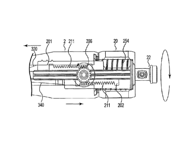
respect to diagnostic imaging. Similarly, interventional procedures, which
have
traditionally used X-ray imaging for guidance, stand to benefit greatly from
MRI's
soft tissue imaging capabilities. In addition, the significant patient
exposure to
ionizing radiation associated with traditional X-ray guided interventional
procedures is eliminated with MRI guidance.
[0003] A variety
of MRI techniques are being developed as alternatives to X-
ray imaging for guiding interventional procedures. For example, as a medical
device is advanced through the patient's body during an interventional
procedure,
its progress may be tracked so that the device can be delivered properly to a
target
site. Once delivered to the target site, the device and patient tissue may be
monitored to improve therapy delivery. Thus, tracking the position of medical
devices is useful in interventional procedures. Exemplary
interventional
procedures include, for example, cardiac electrophysiology procedures
including
diagnostic procedures for diagnosing arrhythmias and ablation procedures such
as
atrial fibrillation ablation, ventricular tachycardia ablation, atrial flutter
ablation,
- 1 -
Attorney Docket No.: 23268-4204
CA 02894763 2015-06-10
WO 2014/093457
PCT/US2013/074331
Wolfe Parkinson White Syndrome ablation, AV node ablation, SVT ablations and
the like. Tracking the position of medical devices using MRI is also useful in
oncological procedures such as breast, liver and prostate tumor ablations; and
urological procedures such as uterine fibroid and enlarged prostate ablations.
[0004] MRI uses three fields to image patient anatomy: a large static magnetic
field, a time-varying magnetic gradient field, and a radiofrequency (RF)
electromagnetic field. The static magnetic field and time-varying magnetic
gradient field work in concert to establish both proton alignment with the
static
magnetic field and also spatially dependent proton spin frequencies (resonant
frequencies) within the patient. The RF field, applied at the resonance
frequencies, disturbs the initial alignment, such that when the protons relax
back
to their initial alignment, the RF emitted from the relaxation event may be
detected and processed to create an image.
[0005] Each of the three fields associated with MRI presents safety risks to
patients when a medical device is in close proximity to or in contact either
externally or internally with patient tissue. One important safety risk is the
heating that may result from an interaction between the RF field of the MRI
scanner and the medical device (RF-induced heating), especially medical
devices
that have elongated conductive structures, such as braiding and pull-wires in
catheters and sheaths.
[0006] The RF-induced heating safety risk associated with elongated metallic
structures in the MRI environment results from a coupling between the RF field
and the metallic structure. In this case several heating related conditions
exist.
One condition exists because the metallic structure electrically contacts
tissue. RF
currents induced in the metallic structure may be delivered into the tissue,
resulting in a high current density in the tissue and associated Joule or
Ohmic
tissue heating. Also, RF induced currents in the metallic structure may result
in
increased local specific absorption of RF energy in nearby tissue, thus
increasing
the tissue's temperature. The foregoing phenomenon is referred to as
dielectric
heating. Dielectric heating may occur even if the metallic structure does not
electrically contact tissue, such metallic braiding used in a deflectable
sheath. In
addition, RF induced currents in the metallic structure may cause Ohmic
heating
- 2 -
Attorney Docket No.: 23268-4204
CA 02894763 2015-06-10
WO 2014/093457
PCT/US2013/074331
in the structure, itself, and the resultant heat may transfer to the patient
In such
cases, it is important to attempt to both reduce the RF induced current
present in
the metallic structure and/or eliminate it, all together by eliminating the
use of
metal braid and long metallic pull-wires.
[0007] The static field of the MRI will cause magnetically induced
displacement
torque on any device containing ferromagnetic materials and has the potential
to
cause unwanted device movement. It is important to construct the sheath and
control handle from non-magnetic materials, to eliminate the risk of unwanted
device movement.
[0008] When performing interventional procedures under MRI guidance, clinical
grade image quality must be maintained. Conventional steerable sheaths are not
designed for the MRI and may cause image artifacts and/or distortion that
significantly reduce image quality. Constructing the sheath from non-magnetic
materials and eliminating all potentially resonant conductive structures
allows the
sheath to be used during active MR imaging without impacting image quality.
Similarly, it is as important to ensure that the control handle is also
constructed
from non-magnetic materials thereby eliminating potentially resonsant
conductive
structures that may prevent the control handle being used during active MR
imaging.
[0009] Conventional steerable sheaths utilize metallic braiding for torque
delivery
and kink resistance; metallic pull-wires and anchor bands for distal tip
deflection;
metallic marker bands for fluoroscopy visualization; and ferromagnetic metals
in
the control handle to minimize cost. Thus because the pull-wires incorporate a
conductive materials they will react with the RF field of the MRI scanner and
result in RF heating and the associated danger to patients and image
degradation
and artifacts. Additionally, the control handles incorporate ferromagnetic
materials that may be attracted to the strong static magnetic field of the MRI
scanner. Moreover, the fluoroscopy marker bands in conventional designs may
not be compatible with the MR environment due to static field interactions and
image degradation and, therefore, are not optimal for visibility in the MRI
environment. Therefore, visualization within the MR environment may require
the use of either passive or active MR tracking techniques. Passive tracking
- 3 -
Attorney Docket No.: 23268-4204
CA 02894763 2015-06-10
WO 2014/093457
PCT/US2013/074331
techniques include passive markers that may lead to image distortion due to
direct
currents or the use of inductively coupled coils. Active tracking is more
robust
than passive tracking but involve resonant RF coils that are attached to the
device
and directly connected to an MR receiver allowing for the determination of the
three-dimensional coordinates of the resonant RF coils within the scanner. To
the
inventors' knowledge neither active nor passive tracking techniques are
presently
utilized in conventional steerable sheaths or control handles.
[0010] Thus, there is a need for a steerable sheath catheter and control
handle that
are built with MR compatible materials to eliminate the magnetic resonance
environment limitations of conventional sheaths while maintaining other
characteristics of conventional sheaths. In particular, there is a need for a
more
efficient way to delivery tools and other instruments into a body cavity or
passageway during treatment in an MR environment.
BRIEF SUMMARY OF THE INVENTION
[0011] The foregoing need is addressed by the steerable sheath and control
handle in accordance with the invention. In one aspect of the invention a
steerable
sheath is provided that may be used in an MRI environment to deliver a variety
of
tools (catheters, guidewires, implantable devices, etc.) into the lumens of
the
body. In a further aspect of the invention, the steerable sheath comprises a
reinforced polymer tube in which the reinforcing material is non-metallic
based
(Kevlar, PEEK, Nylon, fabric, polyimide, etc.) or a hybrid of metallic and non-
metallic materials and the reinforcing geometry may comprise a braid, a coil,
or a
slit tube that mimics a coil and combinations of the foregoing. In yet another
aspect of the invention, the reinforced polymer tube may also be segmented
with
varying flexibility along its length to provide the user with the ability to
deflect
the catheter in a region in which the segment is more flexible than other
segments.
In yet another aspect of the invention the polymer tube may also include one
or
more passive visualization markers along the length of the tube and/or one or
more active visualization markers along the length of the tube.
[0012] The steerable sheath in accordance with the invention also includes one
or
more pull-wires which are coupled with the reinforced tube and that allow the
user
- 4 -
Attorney Docket No.: 23268-4204
CA 02894763 2015-06-10
WO 2014/093457
PCT/US2013/074331
to manipulate and deflect the polymer tube. In one aspect of the invention,
the
pull-wires are preferably made of a non-metallic material (Kevlar, PEEK,
Nylon,
fabric, etc.). One or more internal pull-wire lumens are positioned within the
polymer tube construct and allow the user to manipulate the pull-wires to move
smoothly during actuation. One or more anchor points connect the pull-wire in
the distal portion of the polymer tube.
[0013] In another aspect of the invention a control handle on the proximal end
of
the reinforced tube operates longitudinal movement of the pull-wire(s). In one
aspect of the invention, the handle includes paramagnetic or diamagnetic
materials
or combinations of paramagnetic and diamagnetic materials.
[0014] In another aspect of the invention, an MR compatible deflectable
catheter
is provided. The MR compatible deflectable catheter includes a steerable
sheath
having a tubular shaft, said tubular shaft receiving first and second
longitudinal
movement wires operably coupled to a distal end thereof; a control handle
having
a main body configured to receive first and second rack screws, said second
rack
screw including a threaded portion on an outer surface at a distal end
thereof; said
first longitudinal movement wire operably coupled to said first rack screw and
said second longitudinal movement operably coupled to said second rack screw;
and a rotatable adjustment knob operably engageable with said control handle,
said rotatable adjustment knob having an internal threaded portion matingly
engageable with the threaded portion of said second rack screw, said rotatable
adjustment knob moveable between a first position in which the internal thread
is
configured to engage the thread on the outer surface of said second rack screw
and
cause said second rack screw to move proximally to cause proximal longitudinal
movement of the second longitudinal movement wire and a second position in
which the internal thread is configured to move said second rack screw in a
distal
direction to release tension on the second longitudinal movement wire
In another aspect of the invention a method of using the MR compatible
steerable
sheath is also provided. A method of deflecting a deflectable catheter
includes
providing a steerable sheath having a tubular shaft, the tubular shaft
receiving first
and second longitudinal movement wires having first and second ends, the first
end operably coupled to a distal end of the tubular shaft; providing a control
- 5 -
CA 02894763 2016-10-24
=
handle having a main body configured to receive first and second rack screws,
the
first and second rack screws including an inner threaded channel and an outer
surface,
the outer surface of the second rack screw including a thread at a distal end
thereof,
wherein the second end of the first longitudinal movement wire is operably
coupled to
the first rack screw and wherein the second end of the second longitudinal
movement
is operably coupled to the second rack screw; first and second pinion gears
coupled to
the tubular shaft of the steerable sheath and operably engageable with the
inner
threaded channel of the first and second rack screws; and a rotatable
adjustment knob
having an internal thread engageable with the threaded outer surface of the
second
rack screw and moveable between a first position and second position; rotating
the
rotatable adjustment knob in the first position to cause engagement of the
outer thread
of the second rack screw such that the second rack screw moves proximally
longitudinally, wherein the proximal longitudinal movement of the second rack
screw
causes engagement of the pinion gears on the inner threaded channel; causing
the
pinion gears to movably advance along the threaded internal channel in the
distal
direction relative to the second rack screw and in the proximal direction
relative the
first rack screw thereby causing the first rack screw to move distally thereby
releasing
tension on the first longitudinal movement wire and causing the second rack
screw, to
move proximally thereby causing tension on the second longitudinal movement
wire
to moveably cause the distal end of the steerable sheath to deflect to at
least 180
degrees in a first direction from a longitudinal axis of the tubular shaft;
rotating the
rotatable adjustment knob in the second direction; causing the pinion gears to
movably advance along the threaded internal channel in the proximal direction
relative to the second rack screw and in the distal direction relative to the
first rack
screw thereby causing the second rack screw to move distally thereby releasing
tension on the second longitudinal movement wire and causing the first rack
screw to
move proximally thereby causing tension of the first longitudinal movement
wire
thereby causing the distal end of the steerable sheath to deflect to at least
180 degrees
in a second direction from a longitudinal axis of the tubular shaft.
- 6 -
CA 02894763 2016-10-24
[0014a] In accordance with an aspect of an embodiment, there is provided an MR
compatible deflectable catheter comprising: a steerable sheath having a
tubular shaft
defining a longitudinal axis, said tubular shaft receiving first and second
longitudinal
movement wires operably coupled to a distal end thereof; a control handle
having a
main body configured to receive first and second rack screws, said first and
second
rack screws being mechanically coupled to each other such that movement of
said
second rack screw along the longitudinal axis of the tubular shaft causes
movement of
said first rack screw in an opposite direction along the longitudinal axis of
the tubular
shaft, said second rack screw including a threaded portion on an outer surface
at an
end thereof; said first longitudinal movement wire operably coupled to said
first rack
screw and said second longitudinal movement wire operably coupled to said
second
rack screw; and a rotatable adjustment knob operably engageable with said
control
handle, said rotatable adjustment knob having an internal threaded portion
matingly
engageable solely with the threaded portion on the outer surface of said
second rack
screw, said rotatable adjustment knob moveable between a first position and a
second
position in which the internal threaded portion is configured to engage solely
the
threaded portion on the outer surface of said second rack screw, wherein said
first
position causes said second rack screw to move proximally along the
longitudinal axis
of the tubular shaft which in turn causes said first rack screw to move
distally along
the longitudinal axis of the tubular shaft and proximal movement of said
second rack
screw is configured to tension and cause proximal longitudinal movement of the
second longitudinal movement wire, and further wherein said second position is
configured to move said second rack screw distally along the longitudinal axis
of the
tubular shaft which in turn causes said first rack screw to move proximally
and distal
movement of said second rack screw is configured to release tension on the
second
longitudinal movement wire.
[0014b] In accordance with another aspect of an embodiment, there is provided
a
method of deflecting a deflectable catheter comprising: providing a steerable
sheath
having a tubular shaft defining a longitudinal axis, said tubular shaft
receiving first
and second longitudinal movement wires having first and second ends, said
first ends
operably coupled to a distal end of said tubular shaft and said second ends
operably
coupled to first and second rack screws; providing a control handle having a
main
body configured to receive said first and second rack screws, said first and
second
- 6a -
CA 02894763 2016-10-24
rack screws mechanically coupled to each other by mechanical coupling means
such
that movement of said second rack screw along the longitudinal axis of the
tubular
shaft causes movement of said first rack screw in an opposite direction along
the
longitudinal axis of the tubular shaft, said second rack screw including a
threaded
portion on an outer surface at an end thereof; providing a rotatable
adjustment knob
having an internal thread matingly engageable solely with the threaded portion
on the
outer surface of said second rack screw and moveable between a first position
and a
second position in which the internal thread is configured to engage solely
the
threaded portion on the outer surface of said second rack screw; rotating said
rotatable
adjustment knob to said first position thereby causing engagement of the
threaded
portion on the outer surface of said second rack screw such that said second
rack
screw moves proximally along the longitudinal axis of the tubular shaft and
proximal
movement of said second rack screw causes distal movement of said first rack
screw
thereby releasing tension on the first longitudinal movement wire and causes
proximal
longitudinal movement of the second longitudinal movement wire; rotating said
rotatable adjustment knob to said second position thereby causing engagement
of the
threaded portion on the outer surface of said second rack screw such that said
second
rack screw moves distally along the longitudinal axis of the tubular shaft and
distal
movement of said second rack screw thereby releases tension of the second
longitudinal movement wire and causes said first rack screw to move proximally
thereby causing proximal longitudinal movement of the first longitudinal
movement
wire.
[0015] These and other features of the invention will now be described in
detail with
reference to the accompanying Figures.
- 6b -
Attorney Docket No.: 23268-4204
CA 02894763 2015-06-10
WO 2014/093457
PCT/US2013/074331
BRIEF DESCRIPTION OF THE DRAWINGS
[0016] For a better understanding of the invention, and to show how the same
may be carried into effect, reference will now be made, by way of example, to
the
accompanying drawings, in which:
[0017] FIG. 1 is a perspective view of a control handle that may operably
coupled
with the steerable sheath according to an aspect of the invention.
[0018] FIG. 2 is an exploded perspective view of the control handle and
steerable
sheath according to an aspect of the invention.
[0019] FIG. 3 is a perspective view of the steerable sheath according to an
aspect
of the invention.
[0020] FIG. 4 is a perspective view of the steerable sheath according to an
aspect
of the invention with the steerable distal tip cut away to show detail.
[0021] FIG. 5A is an enlarged view of the pull wires at the proximal end of
the
steerable sheath in accordance with the invention.
[0022] FIG. 5B is a detailed view of a pull ring that provides a contact point
between the pull wire and the distal end of the steerable sheath in one aspect
of the
invention.
[0023] FIG. 6 is a side view of the control handle and steerable sheath
according
to an aspect of the invention.
[0024] FIG. 7 is an enlarged view of the control handle mechanical structure
denoted by 600 in FIG. 6 and showing clockwise rotation of rotatable knob.
[0025] FIG. 8 is an enlarged view of the control handle mechanical structure
denoted by 800 in FIG. 6 and showing counterclockwise rotation of rotatable
knob.
- 7 -
CA 02894763 2016-10-24
[0026] FIG. 9 is a side view of the control handle according to an aspect of
the
invention showing the function of the pull wire.
DETAILED DESCRIPTION OF THE INVENTION
[0027] Numerous structural variations of an MR compatible steerable sheath and
control handle in accordance with the invention are contemplated and within
the
intended scope of the invention. Those of skill in the art will appreciate
that the
exemplary control handle may be coupled to other types of steerable sheaths.
In
addition, those of skill in the art will appreciate that the exemplary
steerable sheath
may be couple with other control handles. Therefore, for purposes of
discussion and
not limitation, an exemplary embodiment of the MR compatible steerable sheath
and
control handle will be described in detail below.
[0028] Referring now to FIG. 1, the control handle 10 in accordance with the
invention includes a cover 2 as illustrated in FIG. 1. Cover 2 includes distal
portion
12, hand-graspable middle region 14, and proximal end 16. Distal portion 12
includes
aperture 18 through which steerable sheath 100 exits. Proximal end 16 includes
rotatable adjustment knob 20 and port 22. Rotatable adjustment knob 20 is
operably
coupled to a proximal end (not shown) of steerable sheath 100 such that
rotation of
the knob causes movement of steerable sheath 100 as hereinafter described.
Port 22
includes an aperture therethrough for receiving a medical device such as by
way of
example an MR-compatible electrode circuit such as that disclosed in U.S.
Publn. No.
2011/0046707.
[0029] Referring now to FIG. 2 an exploded view of the control handle 10 and
steerable sheath 100 in accordance with the invention is shown. Cover 2 of
control
handle 10 includes a first mating portion 24 and a second mating portion 26.
Those of
skill in the art will appreciate, however, that cover 2 may include any number
of
mating portions and still be within the scope of the invention. Each of the
first and
second mating portions 24, 26 include an inner face 30 having a plurality of
inserts 32
fixedly coupled to inner face 30. As depicted, inserts 32 include a receiving
groove
therewithin. When first mating portion and
- 8 -
Attorney Docket No.: 23268-4204
CA 02894763 2015-06-10
WO 2014/093457
PCT/US2013/074331
second mating portion are operably coupled, receiving groove 34 forms a lumen
into which steerable sheath 100 is received. First mating portion 24 and
second
mating portion 26 when mated form an internal recess 40 at a distal end
thereof,
which accommodates first and second rack screws 201, 202. It should be noted
that the distal threads 236 of the first rack screw 201, although shown, have
no
function. First and second rack screws 201, 202 are mirror images of each
other.
Therefore, the distal threads 236 of the first rack screw 201 are present to
reduce
the cost of manufacturing so that first and second rack screws 201, 202 can be
made from the same mold. Control handle 10 further includes first and second
pinion gears 204, 206, t-valve axel 208, first and second pegs 210, 212, t-
valve
214, tube retainer 216, tube 218, and rotatable adjustment knob 20. Rotatable
adjustment knob 20 receives seals 230, seal cap 232 and fitting 234. First and
second pegs 210, 212 are operably coupled to t-valve axel 208. Groove 41
receives pegs 210, 212. First and second pegs 210, 212 receive pinion gears
204
and 206. Tube 218 attaches to a stopcock in t-valve which connects to a
syringe
for flushing or aspirating the steerable catheter.
[0030] As may be seen in FIG. 2, second rack screw 202 includes distal threads
238 on an outer surface thereof. Threaded distal end 238 is operably received
by
an inset 40 in the proximal end of first and second mating covers 24, 26. An
internal central channel of each of first and second rack screws 201, 202
includes
a threaded portion 211 that threadably receives pinion gears 204, 206 in
operation.
First and second rack screws 201, 202 include notched portion 203, 205. First
and
second pull wires 320, 340 are routed and are operably coupled to ends 230,
252
of each rack screw 201, 202, respectively. Pinion gears 204, 206 are received
by
pegs 210, 212 operably coupled to t-valve axel 208. In operation, posts 210,
212
are received by and move longitudinally on notched portion 203, 205
respectively.
This allows threaded pinion gears 204, 206 to be received by and move
longitudinally along the threaded central channel of each of first and second
rack
screws 201, 202.
[0031] Rotatable adjustment knob 20 includes internal threads 254
circumferentially disposed about an inner wall thereof. Internal threads 254
will
engage the distal threads 238 of the second rack screw 202. As the rotatable
- 9 -
Attorney Docket No.: 23268-4204 CA 02894763 2015-06-10
WO 2014/093457
PCT/US2013/074331
adjustment knob is rotated clock-wise the internal adjustment knob threads 254
engage the distal threads 238 of the second rack screw 202 causing
longitudinal,
proximal movement of rack screw 202. As the rotatable adjustment know is
rotated counter-clockwise the internal threads (still engaged with the distal
threads
238 of the second rack screw 202) causes longitudinal, distal movement of rack
screw 202.
[0032] Referring now to FIG. 3, the steerable sheath 100 in accordance with
the
invention will now be explained. Steerable sheath 100 may be used in an MRI
environment to deliver a variety of tools such as catheters, guide wires,
implantable devices, etc. into cavities and passageways of a patient body. The
steerable sheath 100 includes a deflectable tip portion 200 that is able to
bend at
least 180 degrees offset from the longitudinal axis of the catheter sheath
100. This
flexibility allows the medical professional to make very tight turns to
deliver the
aforementioned tools to the cavities and passageways of the patient body.
[0033] Referring again to FIG. 3 a perspective view of an MR compatible
steerable sheath that is suitable for use in an MRI environment is depicted.
The
MR compatible steerable sheath 100 in accordance with the invention broadly
includes tubular shaft 120 with distal 140 and proximal ends 160. Tubular
shaft
120 includes an outer diameter 130, an inner diameter 150 and defines a
central
lumen 300 therewithin. Tubular shaft may be constructed of a variety of
polymers
such as pebax, polyurethane, nylon, derivatives thereof and combinations of
the
foregoing.
[0034] Distal end 14 includes transition section 180, deflectable tip portion
200,
and magnetic marker 220. Pressure relief holes 240, 260 may be formed in the
tubular shaft 120 at the distal end 140. Those of skill in the art will
appreciate that
while only two pressure relief holes 240, 260 are shown there may any number
of
pressure relief holes formed and still be within the scope of the invention.
When
retracting an item housed by the sheath 100, such as a catheter or MR active
tracking system, pressure may form at the end of the sheath thereby drawing or
sucking in tissue. Pressure relief holes 240, 260 are designed to reduce this
pressure thereby ameliorating the risk of tissue damage.
-10-
Attorney Docket No.: 23268-4204
CA 02894763 2015-06-10
WO 2014/093457
PCT/US2013/074331
[0035] Transition section 180 is optionally included for purposes of
manufacturability. The deflectable tip section 20 has a significantly lower
durometer making it more malleable and flexible than the main body portion 170
of tubular shaft 120 which has a higher durometer or, in other words, quite
stiff.
As a consequence, these two sections do not bond to one another well.
Transitional section 180 has a mid-range durometer allowing it to bond well to
both the deflectable tip section 200 and the main body 170 of the tubular
shaft
120. Those of skill in the art will appreciate that the transition section 180
may be
of any length desired so as to provide an adequate transition between the
distal tip
portion 200 and the main body portion 170. In one exemplary embodiment
transition section may range from about 0.25 to about 0.75 inches. In
addition,
those of skill in the art will appreciate that transition section may be
eliminated
and the deflectable tip section 200 may be coupled to the main body 170 of
tubular shaft 120 by means known to those of skill in the art without
departing
from the spirit of the invention.
[0036] Steerable sheath 100 includes central lumen 300 therewithin. In one
aspect of the invention, the inner diameter 150 of the tubular shaft 120 is
approximately 6 French or greater but those of skill in the art will
appreciate that
varying internal diameters may be used depending on the particular application
without departing from the scope of the present invention. Central lumen 300
may include one or more liners (not shown) disposed therewithin to allow for
easier movement of instruments therethrough. Liners may comprise materials
made from polytetrafluoroethylene (PTFE), fluorinated ethylene propylene
copolymer (FEP), nylons and combinations of the foregoing. Alternatively, the
lumen 300 may be coated with any such polymers. The polymer tubular shaft
120 may also include one or more passive visualization markers, such as a
ferrous
or magnetic marker 220, disposed circumferentially about the tubular shaft 120
at
one or more locations along the length thereof and/or one or more active
visualization markers such as an active tracking coil along the length of the
tube.
An active tracking coil may comprise one or more small antennas integrated
into
the device and include traces on a circuit board, coiled wire, and/or a
dipole. If
an active visualization marker is used, one or more devices may be included in
the
conductors to mitigate RF field heating may be included. Such devices include
- 11 -
Attorney Docket No.: 23268-4204
CA 02894763 2015-06-10
WO 2014/093457
PCT/US2013/074331
chokes, transformers, impedances, and other such devices known to those of
skill
in the art. One or more fluoroscopy markers (not shown) may also be included
along the length of the polymer tubular shaft 12.
[0037] One or more optional fluid ports (not shown) may be located on the
proximal end 16 of the tubular shaft 12 to allow for homeostasis of the sheath
with
the patient body. The fluid port(s) allows access for the user or physician to
aspirate blood from the steerable sheath lumen 30 and flush with saline.
Aspirating and flushing of the sheath prevents air from entering the body
before
and during insertion of a tool and/or catheter.,
[0038] Referring now to FIG. 4 a cut away view of the steerable sheath 100 in
accordance with the invention depicts a reinforcement construct 320 of the
tubular
shaft 120. As shown, the geometry of the reinforcement construct 320 is
braided
but those of skill in the art will appreciate that the reinforcement construct
320
may comprise other configurations so long as it imparts the necessary
deflectability to the tubular shaft 120 at the distal end. For example the
reinforcement geometry may be a coil or a slit tube that mimics a coil or
combinations of the foregoing. The reinforcement of the tubular shaft 120 may
extend from the distal end 140 to the proximal end 160 or may extend from the
deflectable tip section 200 to approximately the transition section 180 of the
tubular shaft 12.
[0039] The material used in the reinforcement construct 320 may be non-
metallic
such as Kevlar, PEEK, Nylon, fabric, polyimide, fiber optic, silica glass and
the
like or may also be hybrid of metallic, such as stainless steel, and non-
metallic
materials. Those of skill in the art will appreciate that, the reinforced
polymer
tubular shaft 140 may be segmented and each segment may be constructed with
varying flexibility along the segment to provide the user with the ability to
deflect
the sheath in a region in which the segment is more flexible than in other
segments. Varying flexibility and thus deflectability may be accomplished by
having braids or coils that have greater braiding or coils per sq. cm than in
other
segments where the braiding or coiling would be less per sq. cm. Flexibility
and
deflectability may also be accomplished by the varying durometers as herein
described.
- 12 -
Attorney Docket No.: 23268-4204
CA 02894763 2015-06-10
WO 2014/093457
PCT/US2013/074331
[0040] Referring now to FIG. 5A, an enlarged view of the proximal end 160 of
the steerable sheath 100 in accordance with the invention is depicted.
Proximal
end 160 of the steerable sheath is operably coupled to control handle 10
depicted
in dashed lines and as hereinafter described. The steerable sheath 100 in
accordance with the invention includes one or more pull-wires 320, 340 which
are
operably coupled at a pull-wire proximal end 342 to the control handle 10 as
hereinafter will be described. The portion of the pull-wires 320, 340 that are
operably coupled to the control handle exit the tubular body 120 at opening
122.
The portion of the pull-wires 320, 340 that are operably coupled to pull ring
440
(as best seen in FIG. 5B) extend through a lumen constructed from a sheet of
polymeric material fastened to an inner portion of tubular shaft 120 for a
length
thereof and enter tubular shaft 120 through entrance holes 330, 350 on
opposing
sides of tubular shaft 120. Pull-wires 320, 340 allow the user to manipulate
and
deflect the one or more flexible segments along the length of the polymer
tubular
shaft 120 and in particular the deflectable tip portion 200. In one aspect of
the
invention, the pull-wires 320, 340 are preferably made of a non-metallic
material
(Kevlar, PEEK, Nylon, fabric, etc.).
[0041] One or more internal pull-wire lumens 360 are constructed of a
flexible,
non-metallic material such as PTFE. Internal pull-wire lumens 360 facilitate
smooth manipulation of the pull-wires 320, 340 during actuation. Internal pull-
wire lumens 360 have an outer diameter of approximately 0.12 inches and an
inner diameter of approximately 0.010 inches. However, those of skill in the
art
will appreciate that the dimensions of the internal pull-wire lumens 360 may
vary
with the dimensions of both the pull-wires 320, 340 and the tubular shaft 120
so
long as they are dimensioned to house the pull-wires and allow pull-wires to
move
smoothly during actuation.
[0042] Referring to FIG. 5B, a side view of the distal end of the steerable
sheath
in accordance with the invention is shown. Pull wires 320, 340 are operably
coupled at their distal end to an opening 440 in pull ring 442 positioned
within
lumen 300 at the deflectable tip 200 end of the steerable sheath 100.
[0043] Referring now to FIGS. 6-9 an exemplary control handle 31 for operating
the steerable sheath is disclosed. As discussed in reference to FIG. 2,
control
- 13 -
Attorney Docket No.: 23268-4204
CA 02894763 2015-06-10
WO 2014/093457
PCT/US2013/074331
handle 310 allows the user to control the longitudinal movement of pull-wires
320, 340 which in turn "pull" or deflect the distal end 140 of the steerable
sheath
100 in opposite directions. Control handle 310 is positioned on the proximal
end
of the steerable sheath 100 and operates longitudinal movement of the pull-
wire(s)
and correspondingly, directional movement of the steerable sheath 100. In one
aspect of the invention, control handle 310 includes paramagnetic or
diamagnetic
materials or combinations of paramagnetic and diamagnetic materials.
[0044] Referring now to FIGS. 6 and 7, FIG. 7 is an enlarged view of the
control
handle of FIG. 6 denoted at numeral 600. Adjustment knob 20 is rotated in the
clockwise direction, which causes internal threads 254 to engage threads 238
of
second rack screw 202 and longitudinal, proximal movement of the second rack
screw. At the same time, the pinion gear is engaged by the longitudinal
movement of the second rack screw. This causes the first rack screw to move in
the opposite direction, i.e. distally. Distal movement of the first rack screw
releases tension in the first pull wire 320. As the rotatable adjustment knob
20
continues to be rotated in a clockwise direction pinion gears 204, 206
operably
engage threaded portion 211 of first and second rack screws and fixes the rate
of
linear travel of opposite pinion gear as best seen in FIG. 7.
[0045] As rotatable adjustment knob 20 is rotated in the clockwise direction
and
engages rack screws which in turn engage pinion gears, second pull wire 340 is
pulled toward the proximal direction as best seen in FIG. 6. In turn, the
tension on
first pull wire 320 is released. As second pull wire 340 is pulled in the
proximal
direction deflectable tip moves in one direction, shown as a downward
direction in
FIG. 6 however those of skill in the art will appreciate that the direction of
deflectable tip is relative to how or the direction in which the user is
holding the
handle 10. When pinion gears 204, 206 abut stop 205 in second rack screw 202
further movement of rotatable adjustment knob 20, pinion gears 204, 206 and
deflectable tip is halted.
[0046] Referring now to FIG. 8 and 9 the opposite function is illustrated.
Adjustment knob 20 is rotated in the counter-clockwise direction, internal
threads
254 engage threads 238 of second rack screw 201 causing longitudinal, distal
movement. As the rotatable adjustment knob 20 continues to be rotated in a
- 14 -
Attorney Docket No.: 23268-4204
CA 02894763 2015-06-10
WO 2014/093457
PCT/US2013/074331
counter-clockwise direction, pinon gears 204, 206 once again operably engage
threaded portion 211 of first and second rack screws which fixes the rate of
linear
travel of the opposite pinion gear as best seen in FIG. 8.
[0047] As rotatable adjustment knob 20 is rotated in the counter-clockwise
direction first pull wire 320 is pulled toward the proximal direction as best
seen in
FIG. 9. In turn, the tension on second pull wire 340 is released. As first
pull wire
320 is pulled in the proximal direction deflectable tip moves in the opposite
direction, shown as an upward direction in FIG. 9. However those of skill in
the
art will appreciate that the direction of deflectable tip is relative to how,
or the
direction in which, the user is holding the handle 10. When pinion gears 204,
206
abut stop 203 in first rack screw 202 further movement of rotatable adjustment
knob 20, pinion gears 204, 206 and deflectable tip is halted.
[0048] Although the present invention has been described with reference to
preferred embodiments, workers skilled in the art will recognize that changes
may
be made in form and detail without departing from the spirit and scope of the
invention.
-15-