Note: Descriptions are shown in the official language in which they were submitted.
CA 02894874 2015-11-13
HAIR STYLING APPARATUS
BACKGROUND
1. Technical Field
100011 The present disclosure relates to an apparatus for treating hair, and,
more particularly,
relates to a hair styling apparatus incorporating a cartridge with an
ultrasound transducer for
heating and at least partially vaporizing a hair treatment agent dispensable
from the cartridge.
2. Background of the Related Art
100021 Hair straightener apparatii typically include two pivotal handles which
are hinged at one
end and pivot about the hinge between open and closed positions. Heating heads
extend from
each handle and have inner surfaces comprised of a heatable material, usually
metal, for
straightening or styling hair. An electric heater clement located beneath each
heatable surface is
activated to warm the surfaces to a desired temperature. The inner surfaces
are positionable
around hair to be styled, and the hinged handles are moved to a closed
position bringing the
heated inner surfaces in contact with the hair. The gripped handles are then
slid along the hair
strands until the hair exits from the heads. One example of a hair
straightener apparatus is
disclosed in commonly assigned U.S. Patent No. 7,178,532.
1
CA 02894874 2015-06-11
WO 2014/093783 PCT/US2013/074937
SUMMARY
[0003] Accordingly, the present disclosure is directed to further
enhancements in hair
straightener apparatti. In accordance with one embodiment, a hair styling
apparatus includes
first and second handle members adapted for movement between an open position
for receiving
hair therebetween and a closed position adjacent the hair, a heating element
associated with at
least one of the first and second handle members and a cartridge mountable to
the first handle
member and having a hair treatment agent for dispensing and treating hair
disposed between the
first and second handle members. The treatment agent may include a
conditioning,
strengthening, repairing or revitalizing fluid.
[0004] An ultrasonic transducer may be associated with the cartridge. The
transducer is
actuable to heat the treatment agent to affect at least partial vaporization
thereof for release
adjacent the heating elements and application to the hair. The cartridge may
define a cartridge
vapor outlet with the transducer being positioned adjacent the cartridge vapor
outlet. The
transducer may have channels for permitting the at least partially vaporized
treatment agent to
pass through the transducer and the cartridge vapor outlet.
[0005] The heating element of the at least one of the first and second
handle members may
define a channel, which is positioned adjacent the cartridge outlet to convey
vaporized treatment
agent along the heating element. In one embodiment, the first and second
handle members
include respective first and second heating elements with each the heating
element having the
channel for conveying the vaporized treatment agent.
2
CA 02894874 2015-11-13
[0006] A manually actuated ultrasonic power switch for selectively activating
and deactivating
the transducer. The cartridge may include electrical contacts in electrical
communication with the
transducer, and wherein the first handle member includes corresponding handle
contacts for
engaging the electrical contacts of the cartridge for supplying power to the
transducer.
[0007] The cartridge may be dimensioned and adapted for releasable mounting to
the first handle
member. A cartridge release member may be mounted to the first handle member.
The cartridge
release member is movable to cause release of the cartridge from the first
handle member. The
cartridge may include a cover, which is movable between an open condition to
permit
introduction of the treatment agent within the cartridge and a closed
position. The cartridge may
define an internal chamber for accommodating the treatment agent. An absorbent
member may be
disposed within the internal chamber for containing the treatment agent. The
absorbent member is
adjacent the transducer whereby heat generated by the transducer causes at
least partial
vaporization of the treatment agent within the absorbent member. In
embodiments, a container
having the treatment agent is releasably mountable to the cartridge.
[0007a] In accordance with an aspect of the present invention there is
provided a hair styling
apparatus, which comprises:
first and second handle members adapted for movement between an open position
for
receiving hair therebetween and a closed condition adjacent the hair;
a heating element associated with at least one of said first and second handle
members;
a cartridge mountable to said first handle member, said cartridge including a
hair
treatment agent for dispensing and treating hair disposed between said first
and second handle
members; and
3
CA 02894874 2015-11-13
an ultrasonic transducer associated with said cartridge, said transducer
actuable to heat
the treatment agent to effect at least partial vaporization thereof for
release adjacent said heating
element and application to the hair.
BRIEF DESCRIPTION OF THE DRAWINGS
100081 Various embodiments of the present disclosure are described hereinbelow
with references
to the drawings, wherein:
3a
CA 02894874 2015-06-11
WO 2014/093783 PCT/US2013/074937
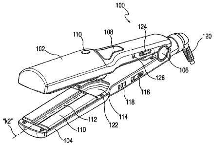
[00091 FIGS. 1-2 are perspective views of a hair styling apparatus in
accordance with the
principles of the present disclosure illustrating the first and second handle
members and the
cartridge mounted to the first handle member;
[0010] FIGS. 3-5 are top plan, side elevation and axial views, respectively
of the hair styling
apparatus;
[0011] FIG. 6 is a perspective view of the hair styling apparatus
illustrating the cartridge
removed;
[0012] FIG. 7 is a top plan view of the cartridge;
[0013] FIG. 8 is a side cross-sectional view of the cartridge taken along
the lines 8-8 of FIG.
7;
[00141 FIG. 9 is an enlarged isolated view of the area of detail designated
in FIG. 8;
[0015] FIG. 10 is a schematic view illustrating a mechanism for releasably
mounting the
cartridge to the first handle member;
[0016] FIG. 11 is a perspective view of the hair styling apparatus with the
second handle
member removed illustrating application of the vaporized hair treatment agent
to the subject's
hair; and
[00171 FIGS. 12A-12C are perspective views of three embodiments of the
cartridge member
illustrated in relation to the hair styling apparatus.
4
CA 02894874 2015-06-11
WO 2014/093783 PCT/US2013/074937
DETAILED DESCRIPTION OF THE PREFERRED EMBODIEMNTS
[0018] Referring now in detail to the drawings and, in particular, to FIGS.
1-5, the hair
styling apparatus 100 in accordance with the principles of the present
invention is illustrated.
The hair styling apparatus 100 may be in the form of a hair straightener
utilized to generally
straighten the hair of the subject. However, it is envisioned that the hair
styling apparatus may
includes surfaces to shape, crimp or affect any styling effect to the
subject's hair.
[0019] The hair styling apparatus 100 includes first and second handle
members 102,104
connected to each other through a hinge 106, of a conventional type. The hinge
106 typically
incorporates a spring to normally bias the first and second members 102, 104
to the open
position depicted in FIGS. 1 and 2. The first and second handle members 102,
104 are adapted to
pivot about the hinge 106 between the open position of FIGS. 1 and 2 and the
closed position
depicted in FIGS. 3-5. The first handle member 102 includes a cartridge 108
and a cartridge
release button 110, which releases the cartridge 108 from the first handle
member 102.
Generally, the cartridge 108 contains a hair treatment agent, which is
released in an at least
partially vaporized state, between the first and second handle members 102,
104 for application
to the subject's hair. The cartridge 108 will be discussed in greater detail
hereinbelow.
[0020] Each of the first and second handle members 102, 104 includes a
heating element or
plate 110 at the end remote from the hinge 106. The heating plates 110 are
heated by
conventional electrical means (not shown) known in the art, so that hair can
be positioned
therebetween for styling. Each heating plate 110 includes a centrally disposed
channel 112
respectively extending lengthwise or longitudinally with respect to the
longitudinal axes "kl. k2"
of the respective handle members 102, 104. The channels 112 may be offset with
respect to the
CA 02894874 2015-06-11
WO 2014/093783 PCT/US2013/074937
respective axes "kl, k2", may be non-linear, arcuate, sinusoidal or any other
shape. The
channels 112 convey the at least partially vaporized treatment agent, which is
released from the
cartridge 108 within the heating plates 110 for application to the hair of the
subject. The second
handle member 104 includes a pocket or recess 114 (FIG. 1), which is
dimensioned to
correspondingly accommodate at least a segment of the cartridge 108 when the
first and second
handle members 102, 104 are in the closed position.
[0021] The first and second handle members 102, 104 may include an on/off
power switch
116, a power-on indicator or light 118 (such as an LED indicator or the like)
for indicating
activation of the apparatus 100 and a power cord 120 for supplying power.
Contacts 122 on each
of the first and second handle member 102, 104 may be provided to power the
heating plates
only when the first and second handle members 102, 104 are in the closed
position. The first
handle member 102 further includes an ultrasound power switch 124 and an
ultrasound power
indicator 126 such as an LED or the like - the function of which will be
discussed in greater
detail herein below.
[0022] Referring now to FIG. 6, in conjunction with FIGS. 7-9, the
cartridge 108 will be
discussed in detail. The cartridge 108 includes a cartridge housing 128 having
a first internal
chamber 130 defining a reservoir for accommodating the treatment agent 132.
The treatment
agent may be argan oil. Argan oil is extracted from the fruits of the argan
tree, argania spinosa,
that is endemic to Morocco. The hair care composition may solely contain argan
oil, or may
include argan oil in combination with other ingredients. Examples of other
ingredients include
pharmaceutically active agents, moisturizers, hydration agents, penetration
agents, preservatives,
emulsifiers, natural or synthetic oils, solvents, surfactants, detergents,
gelling agents, emollients,
antioxidants, fragrances, fillers, thickeners, waxes, odor absorbers,
dyestuffs, coloring agents,
6
CA 02894874 2016-06-03
powders, viscosity-controlling agents, buffers, protectants, pH regulators,
chelating agents,
humectants, conditioners, glitter, mica, minerals, silicones, polyphenols,
sunblocks,
phytomedieinals, and combinations thereof, as well as other additives
typically used in hair care
products as appreciated by those skilled in the art.
[0023] In embodiments, the hair care composition may include argan oil and
emollients
andlor conditioning agents, alone or in combination with other ingredients as
discussed above.
In embodiments, the hair care composition includes argan oil and silicone.
Silicone includes, for
example, silicone oils and oils having a hydrocarbon backbone, silicone oils
combining cyclic
polydimethylsiloxanes, coi-hydroxylated polydimethylsiloxanes, ap-
trimethylsily1
polydimethylsiloxanes, polyorganosiloxanes such as polyalkylmethylsiloxancs,
polymethylphenylsiioxanes, polydiphenyisiloxanes, aminosilicone derivatives,
silicone waxes,
copolyether silicones (such as the oil MIRASIL DMCO sold by Rhone-Poulenc, or
DC 190 sold
by Dow Corning) or mixed silicone derivatives including various types of
derivatization (such, as
poiyalkylinethyl-siloxane/copolyether silicone mixed copolymers). An
argan/silicon
conditioning agent may strengthen, repair or condition hair, while potentially
adding shine to the
hair.
[00241 Other suitable emollients include, for example alkylmonoglyce,rides,
alkyldiglycerides, and/or triglycerides such as oils extracted from plants and
vegetables (palm
oil, coconut oil, cotton seed oil, soybean oil, sunflower oil, olive oil,
grape seed oil, sesame oil,
ground nut oil, castor oil, combinations thereof, and the like), oils of
marine origin (fish oils,
etc.) and derivatives of these oils, such as hydrogenated oils, lanolin
derivatives, mineral oils or
paraffinic oils, perhydrosqualane, squalene, dials such as 1,2-propanediol and
1,3-butanediol,
cetyl alcohol, stearyl alcohol, oleyl alcohol, polyethylene glycols or
polypropylene glycols, and
7
CA 02894874 2015-06-11
WO 2014/093783 PCT/US2013/074937
fatty esters such as isopropyl palmitate, 2-ethylhexyl cocoate, myristyl
myristate, esters of lactic
acid, stearic acid, behenic acid, isostearic acid.
[0025] In embodiments, the hair care composition may include argan oil and
conditioners,
alone or in combination with other ingredients. Conditioners include, for
example, those of
natural or synthetic origin, such as those known under the generic CTFA name
"Polyquaternium", for instance the MIRAPOL A15 or MIRAPOL 550 polymers from
Rhone-Poulenc, cationic polysaccharide derivatives (cationic derivatives of
cellulose, of guar or
of carob), such as cocodimonium hydroxyethyl cellulose, guar hydroxypropyl
trimonium
chloride, hydroxypropyl guar hydroxypropyl trimonium chloride (JAGUAR Cl3S ,
JAGUAR
CI62 sold by Rhone-Poulenc), volatile or non-volatile silicone derivatives,
for instance
amodimethicone, cyclomethicones, water-insoluble, non-volatile
polyorganosiloxanes, for
instance oils, resins or gums, such as diphenyldimethicone gums, combinations
thereof, and the
like.
[0026] Examples of other additives which may be useful in the hair care
composition include
additives for promoting moisturization of the hair and/or skin (wetting
agents), for instance
certain carbohydrates (for example glycerol or sorbitol), polyethylene glycols
or polypropylene
glycols, alkoxylated derivatives of sugars or of sugar derivatives (for
example methylglucose),
water-soluble or water-dispersible polymers such as collagen or certain non-
allergenic
derivatives of marine or plant proteins (for example wheat protein
hydrolysates). Thickeners,
such as natural hydrocolloids (guar gum, carob gum, tam gum, etc.) or
hydrocolloids derived
from fermentation processes, such as xanthan gum, polysaccharides extracted
from seaweed,
such as carrageenans, and polycarbohydrate derivatives such as modified
celluloses (for example
hydroxyethylcellulose, carboxymethylcellulose), or nonionic derivatives (for
example
8
CA 02894874 2015-06-11
WO 2014/093783 PCT/US2013/074937
hydroxypropylguar), anionic derivatives (carboxymethylguar) or
nonionic/anionic mixed
derivatives, such as carboxy-hydroxypropyl-guars or nonionic/cationic
derivatives, can also be
present.
[0027] Referring still to FIGS. 6-9, the cartridge housing 128 may have a
cartridge valve or
cover 134 (FIG. 8), which permits access to the first internal chamber 130.
The cover 134 may
be movable between the closed position and the open position depicted in
phantom in FIG. 8 to
permit filling/refilling of the treatment agent 132 within the first internal
chamber 130 of the
cartridge housing 128. The cartridge housing 128 further includes a second
internal chamber
136 in fluid communication with the first internal chamber 130. The second
internal chamber
136 may have an absorbent member 138 such as a sponge, wicking material or the
like, which
collects and stores a volume of the treatment agent 132.
[0028] The cartridge 108 has an ultrasound emitter or transducer 140 such
as a piezo electric
transducer or the like. The piezo electric transducer 140 may be any
conventional piezo electric
transducer adapted to oscillate to generate energy in the form of heat. The
transducer 140 may
be disc shaped and mounted at each end within opposed channels 142 defined
within the
cartridge housing 128 adjacent or across a cartridge vapor outlet opening 146
of the cartridge
housing 128 (see also FIG. 6). An elastomeric o-ring gasket or seal 148
comprising an
elastomeric material or the like may extend within each channel 144 to form a
fluid tight seal
about the ends of transducer 142. The transducer 142 further includes one or
more micro-
openings or channels 150 extending therethrough in communication with the
second internal
chamber 136 to permit release of the vaporized treatment agent.
[0029] The cartridge 108 further includes one or more power contacts or
pins 152 in
electrical communication with the transducer 142. The power pins 152 are
received within
9
CA 02894874 2015-06-11
WO 2014/093783 PCT/US2013/074937
corresponding power receptacles 154 disposed within the first handle member
102 adjacent the
cartridge receiving recess 156 of the first handle member 102 (FIG. 6). The
power receptacles
154 include electrical contacts, which are in communication with the
ultrasound power switch
124 and the electrical cord 122 to selectively supply power to the transducer
142. Thus, upon
mounting of the cartridge 108 fully within the cartridge receiving recess 156
of the first handle
member 102, the contact pins 152 of the cartridge 108 establish electrical
contact with the
contacts within the pin receiving receptacles 154 of the first handle member
102. The cartridge
receiving recess 156 is correspondingly dimensioned to accommodate the
cartridge 108 in a
manner to reduce the profile of the first handle member 102.
[0030] The cartridge housing 128 may have at least one locking detent 158 ,
which is
selectively engaged by the cartridge release button 110 to releasably secure
the cartridge 108
relative to the first handle member 102. Any type of releasable connection
means are envisioned
including, e.g., tongue and groove arrangements, bayonet couplings, sliding
release arrangements
or the like. In one embodiment schematically depicted in FIG. 10, the
cartridge release button
110 includes a depending resilient member 160, which is receivable within the
locking detent
158 of the cartridge housing 128. Depression of the release button 110 will
cause the resilient
member 160 to deflect in the direction "m" and become released from the
locking detent 158,
thereby permitting removal of the cartridge 108 from the cartridge receiving
recess 156 of the
first handle member 102.
[0031] The use of the hair styling apparatus 100 for styling hair will now
be discussed. The
cartridge 108 filled with the hair treatment agent 132 is mounted within the
outer cartridge
receiving recess 156 of the first handle member 102. Electrical contact is
established between
the contact pins 152 of the cartridge housing 128 and the contacts within the
pin receiving
CA 02894874 2015-06-11
WO 2014/093783 PCT/US2013/074937
receptacles 154 of the first handle member102. The power switch 118 is
activated to charge the
heating elements 110 of the first and second handle members 102, 104. The
subject's hair is
positioned between the open first and second handle members 102, 104 (FIGS. 1
and 2) and the
first and second handle members 102, 104 are moved to the closed position of
FIGS. 3-5. The
hair is treated, e.g., straightened, as it passes along the heating elements
110. When it is desired
to apply the hair treatment agent 132, the transducer power switch 124 is
activated causing the
transducer 142 to oscillate. As the transducer 142 oscillates, heat is
generated sufficient to at
least partially vaporize the treatment agent 132 within the absorbent member
138 in the second
internal chamber 136. As depicted in FIGS. 9 and 11, the vaporized treatment
agent "132v" is
released through the micro-openings 150 extending through the transducer 140
and out the
cartridge vapor outlet opening 146 of the cartridge housing 128. FIG. 11
depicts the first handle
member 102 removed for illustration purposes. The vaporized treatment agent
"132v"
communicates through the opening of the first handle member, and is conveyed
through the
channels 112 of the first and second handle members 102, 104 for application
to the subject's
hair. The treatment agent 132v released in the vaporized state from the
absorbent or wicking
member 138 is continuously replenished with the treatment agent stored within
the first internal
chamber 130. The ultrasound transducer 140 may be deactivated at any time
during the
procedure via the ultrasound power switch 124. In the event more treatment
agent 132 is needed,
the cartridge 108 is released from the first handle member 102 by depression
of the cartridge
release button 110. The closure seal or cover of the cartridge 134 may be
opened, and additional
treatment agent 132 is introduced within the first internal chamber 130. The
cover 134 is closed
and the cartridge 108 is reinserted into the cartridge receiving recess 156 of
the first handle
member 102.
11
CA 02894874 2015-11-13
[0032] The wicking or absorbent member 138 maintains the treatment agent in
the liquid state
adjacent the transducer 140 while preventing the liquid treatment agent from
interfering with the
functioning of the transducer 140. When subjected to heat generated by the
transducer 140, the
treatment agent 132 at least partially vaporizes for release through the
channels 150 of the
transducer 140. The vaporized treatment agent 132v will not interfere with the
functioning of the
transducer. The vaporized treatment agent 132v also protects the hair when
subjected to the heat
of the heating elements 110.
[0033] FIGS 12A-12C illustrate alternate embodiments of the cartridge 108. In
FIG. 12A, the
cartridge 200 is similar to the cartridge 108 of the first embodiment and
incorporates a cover 202
which is selectively opened and closed to permit access to the internal
chambers for refilling of
the treatment agent. In FIG. 12B, the cartridge 300 includes a threaded
opening 302 which
receives a threaded bottle member 304 containing the treatment agent. The
bottle 304 may
replace the first internal chamber and supply the treatment agent to the
absorbent member.
Upon emptying of the bottle 304, the bottle may be released and replaced with
a new bottle of
agent or refilled and connected to the cartridge 300. In FIG. 12C, a flexible
pouch 308, e.g., a foil
pouch, having a threaded segment 310 may be received within the threaded
opening 302 of the
cartridge 300. Multiple pouches 308 may be provided as replacement pouches
during use of the
apparatus 100.
[0034] The above description and the drawings are provided for the purpose of
describing
embodiments of the present disclosure and are not intended to limit the scope
of the disclosure in
any way. It will be apparent to those skilled in the art that various
modifications and variations
can be made without departing from the scope of the disclosure. Thus, it is
intended that
12
CA 02894874 2015-06-11
WO 2014/093783
PCT/US2013/074937
the present disclosure cover the modifications and variations of this
disclosure provided they
come within the scope of the appended claims and their equivalents.
13