Note: Descriptions are shown in the official language in which they were submitted.
ASSISTIVE MANUAL ZEROING VISUALIZATION
BACKGROUND OF THE INVENTION
1. Field of the Invention.
[0001] This invention relates to cardiac catheterization. More
particularly, this invention relates to determination of contact of a cathe-
ter with cardiac tissue.
2. Description of the Related Art.
[0002] Cardiac
arrhythmias, such as atrial fibrillation, occur
when regions of cardiac tissue abnormally conduct electric signals to
adjacent tissue, thereby disrupting the normal cardiac cycle and caus-
ing asynchronous rhythm.
[0003] Procedures for treating arrhythmia include surgically dis-
rupting the origin of the signals causing the arrhythmia, as well as dis-
rupting the conducting pathway for such signals. By selectively ablating
cardiac tissue by application of energy via a catheter, it is sometimes
possible to cease or modify the propagation of unwanted electrical sig-
nals from one portion of the heart to another. The ablation process de-
stroys the unwanted electrical pathways by formation of non-conducting
lesions.
[0004] Verification of physical electrode contact with the target
tissue is important for controlling the delivery of ablation energy. At-
tempts in the art to verify electrode contact with the tissue have been
extensive, and various techniques have been suggested. For example,
U.S. Patent No. 6,695,808 describes apparatus for treating a selected pa-
tient tissue or organ region. A probe has a contact surface that may be
urged against the region, thereby creating contact pressure. A pressure
transducer measures the contact pressure. This arrangement is said to
meet the needs of procedures in which a medical instrument must be
placed in firm but not excessive contact with an anatomical surface, by
1
Date recue/date received 2021-10-19
providing information to the user of the instrument that is indicative of
the existence and magnitude of the contact force.
[0005] As another example, U.S. U.S. Patent No. 6,241,724 de-
scribes methods for creating lesions in body tissue using segmented
electrode assemblies. In one embodiment, an electrode assembly on a
catheter carries pressure transducers, which sense contact with tissue
and convey signals to a pressure contact module. The module identifies
the electrode elements that are associated with the pressure transducer
signals and directs an energy generator to convey radiofrequency en-
ergy to these elements, and not to other elements that are in contact only
with blood.
[0006] A further example is presented in U.S. Patent
No. 6,915,149. This patent describes a method for mapping a heart using
a catheter having a tip electrode for measuring local electrical activity.
In order to avoid artifacts that may arise from poor tip contact with the
tissue, the contact pressure between the tip and the tissue is measured
using a pressure sensor to ensure stable contact.
[0007] U.S. Patent Application Publication 2007/0100332 de-
scribes systems and methods for assessing electrode-tissue contact for
tissue ablation. An electromechanical sensor within the catheter shaft
generates electrical signals corresponding to the amount of movement
of the electrode within a distal portion of the catheter shaft. An output
device receives the electrical signals for assessing a level of contact be-
tween the electrode and a tissue.
[0008] Impedance-based methods for assessing catheter-tissue
contact that are known in the art typically rely on measurement of the
magnitude of the impedance between an electrode on the catheter and a
body-surface electrode. When the magnitude is below some threshold,
the electrode is considered to be in contact with the tissue. This sort of
binary contact indication may be unreliable, however, and is sensitive to
changes in the impedance between the body-surface electrode and the
skin.
2
Date recue/date received 2021-10-19
[0009] U.S. Patent Application Publication Nos. 2008/0288038 and
2008/0275465, both by Sauarav et aL, describe an electrode catheter
system, which may comprise an electrode adapted to apply electric en-
ergy. A measurement circuit adapted to measure impedance may be
implemented between the electrode and ground as the electrode ap-
proaches a target tissue. A processor or processing units may be im-
plemented to determine a contact condition for the target tissue based at
least in part on reactance of the impedance measured by the measure-
ment circuit. In another embodiment, the contact condition may be
based on the phase angle of the impedance.
[0010] U.S. Patent Application Publication No. 2013/0172875 to
Govari et aL, entitled "Contact Assessment Based on Phase Measure-
ment", describes displaying intra-operative phase determinations of an
electrical current passing between the ablation electrode and another
electrode as an indicator of contact force between an ablation electrode
and target tissue.
[0011] Today contact force catheters are commercially available,
for example the THERMOCOOL SMARTTOUCHTm Catheter, produced
by Biosense Webster, Inc., 3333 Diamond Canyon Road, Diamond Bar,
CA 91765.
SUMMARY OF THE INVENTION
[0012] There is provided according to embodiments of the in-
vention a method, which is carried out by inserting a probe having a
contact force sensor into a cavity in a body of a subject, the cavity hay-
ing a blood pool and an endocardial surface, generating an image of the
blood pool, removing a portion of the blood pool from the image to re-
tain a remaining portion of the blood pool thereon, making a determina-
tion from the image that the distal segment of the probe is within the re-
maining portion of the blood pool, and responsively to the determina-
tion manually zeroing the contact force sensor.
[0013] According to one aspect of the method, the removed por-
tion of the blood pool is adjacent the endocardial surface.
3
Date recue/date received 2021-10-19
[0014] According to a further aspect of the method, the removed
portion of the blood pool is adjacent another probe.
[0015] According to an additional aspect of the method, bounda-
ries of the remaining portion of the blood pool are 3 mm from another
probe in the cavity and 10 mm from the endocardial surface.
[0016] According to a further aspect of the method, boundaries
of the remaining portion of the blood pool are 6 mm from another probe
in the cavity and 13 mm from the endocardial surface.
[0017] There is further provided according to embodiments of
the invention a method that is carried out by inserting a probe having a
contact force sensor into a cavity in a body of a subject, the cavity hav-
ing a blood pool and an endocardial surface. The method is further car-
ried out by generating a first image of the blood pool, generating a sec-
ond image to define an excluded region of the blood pool, generating
subtraction images by subtracting the second image from the first image
to define a zero-qualified region of the blood pool, and while generating
the subtraction images navigating the probe within the cavity, until the
distal portion is within the zero-qualified region.
[0018] Another aspect of the method includes making a determi-
nation from the subtraction images that the distal portion is within the
zero-qualified region, and responsively to the determination enabling
manual zeroing of the contact force sensor.
[0019] According to still another aspect of the method, a bounda-
ry of the other excluded region is at least 6 mm from another probe.
[0020] According to an additional aspect of the method, the first
image and the subtraction images include the other probe.
[0021] There is further provided according to embodiments of
the invention an apparatus, including a probe, configured for insertion
into a body cavity having a blood pool, the probe including a contact
force sensor for measuring a force applied to the contact force sensor
and location sensors for detecting a location of the probe in the body
cavity, and a processor, which is configured to receive a plurality of
measurements from the contact force sensor. The processor is operative
4
Date recue/date received 2021-10-19
for generating an image of the blood pool, removing a portion of the
blood pool from the image to retain a remaining portion of the blood
pool thereon, and presenting a location of a distal segment of the probe
on the image.
[0022] According to yet another aspect of the apparatus, the pro-
cessor is operative for making a determination from the image that the
distal segment of the probe is within the remaining portion of the blood
pool, and responsively to the determination enabling manual zeroing of
the contact force sensor.
BRIEF DESCRIPTION OF THE SEVERAL VIEWS OF THE DRAWINGS
[0023] For a better understanding of the present invention, ref-
erence is made to the detailed description of the invention, by way of
example, which is to be read in conjunction with the following drawings,
wherein like elements are given like reference numerals, and wherein:
[0024] Fig. 1 is a pictorial illustration of a system for performing
medical procedures in accordance with an embodiment of the invention;
[0025] Fig. 2 is a schematic drawing of the distal portion of the
catheter shown in Fig. 1 that includes a contact force sensor that can be
adjusted in accordance with an embodiment of the invention;
[0026] Fig. 3 is a schematic diagram of a cardiac chamber in ac-
cordance with an embodiment of the invention;
[0027] Fig. 4 is a flow chart of a method of assistive manual con-
tact force zeroing in a cardiac catheter in accordance with an embodi-
ment of the invention;
[0028] Fig. 5 is a screen display illustrating a phase of the meth-
od of Fig. 4 in accordance with an embodiment of the invention;
[0029] Fig. 6 is a screen display illustrating a phase of the meth-
od of Fig. 4 in accordance with an embodiment of the invention;
[0030] Fig. 7 is a screen display illustrating a phase of the meth-
od of Fig. 4 in accordance with an embodiment of the invention; and
5
Date recue/date received 2021-10-19
[0031] Fig. 8 is a screen display illustrating a phase of the meth-
od of Fig. 4 in accordance with an embodiment of the invention.
DETAILED DESCRIPTION OF THE INVENTION
[0032] In the following description, numerous specific details are
set forth in order to provide a thorough understanding of the various
principles of the present invention. It will be apparent to one skilled in
the art, however, that not all these details are necessarily needed for
practicing the present invention. In this instance, well-known circuits,
control logic, and the details of computer program instructions for con-
ventional algorithms and processes have not been shown in detail in or-
der not to obscure the general concepts unnecessarily.
[0033] In a medical ablation procedure, such as ablation of heart
tissue, it is extremely useful to be able to measure the force applied to
the tissue while the tissue is being ablated. This is because the force ap-
plied is a key parameter governing the amount of tissue ablated for a
given ablation energy input to the tissue. The ablation is typically pro-
vided by a probe comprising an ablation electrode at its distal end. To
accurately measure a force exerted by the distal tip on the endocardi-
um, the force sensor incorporated into the distal end of the probe is typ-
ically calibrated to a "zero level," also referred to herein as a baseline.
The baseline is determined from measurements generated by the force
sensor when the distal tip has minimal contact with any surface (and
therefore there is essentially no effective force exerted on the distal tip).
The baseline may be determined using the techniques disclosed in U.S.
Patent Application Publication No. 2012/0108988 to Ludwin et al.. Once
the baseline is identified, the measurements from the force sensor can
be used to provide a value of the force exerted.
[0034] But such force sensors known in the art typically drift.,
Even if the force exerted on the sensor is constant, readings from the
sensor change. Such drift may be compensated for by zeroing the sen-
sor periodically, typically before applying ablation energy. However,
the zeroing of the sensor should only be applied if the sensor is not con-
6
Date recue/date received 2021-10-19
tacting or in proximity to tissue or other catheters, i.e., the sensor is in a
state where the force on it is effectively zero.
[0035] The force sensor is assumed to be in a zeroed state if over
at least a predetermined interval of time force readings from the sensor
change by less than a predetermined force limit. To ensure that the sen-
sor is in the zeroed state, the probe having the force sensor is typically
also assumed to change its location during the predetermined time in-
terval by more than a predetermined location threshold.
[0036] Commonly assigned Application No. 14/010,697, entitled
"Determining Non-Contact State for a Catheter", teaches how to detect a
zeroed state for the sensor, and to calibrate a zero-force point for the
force sensor. In order to auto-zero the sensor, received signals from the
sensor are checked to detect a situation wherein the sensor is in a first
zeroed state, then in a non-zeroed state (such as if the sensor indicates it
is touching tissue), and then in a second zeroed state. Once such a situa-
tion is detected, force readings from the second zeroed state may be
used as calibration values that zero the sensor.
[0037] The sensor is in a zeroed state where the force on it is ef-
fectively zero (such a state is typically achieved if the sensor is sur-
rounded by blood in the heart chamber, and is not contacting a heart
wall and the probe is not in proximity to another probe. Changes in
proximity between probes may reduce the accuracy of the calibration
values referred to above. In such cases, a probe may be assumed to be
in the zeroed state if, in addition to the force condition described above,
a measured value of the change in proximity to another probe is less
than a predetermined proximity change threshold. In general, there is a
high probability of accurately auto-zeroing the sensor when the sensor
does not contact tissue. In addition, there is an extremely high probabil-
ity of not auto-zeroing the sensor when the sensor does contact tissue.
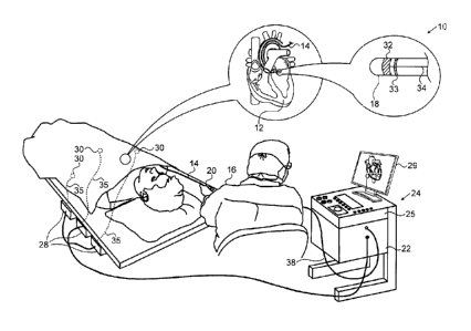
[0038] Turning now to the drawings, reference is initially made to
Fig. 1, which is a pictorial illustration of a system 10 for performing abla-
tive procedures on a heart 12 of a living subject, which is constructed
7
Date recue/date received 2021-10-19
and operative in accordance with a disclosed embodiment of the inven-
tion. The system comprises a catheter 14, which is percutaneously in-
serted by an operator 16 through the patient's vascular system into a
chamber or vascular structure of the heart 12. The operator 16, who is
typically a physician, brings the catheter's distal tip 18 into contact with
the heart wall at an ablation target site. Optionally, Electrical activation
maps may then be prepared, according to the methods disclosed in U.S.
Patent Nos. 6,226,542, and 6,301,496, and in commonly assigned U.S. Pa-
tent No. 6,892,091. One commercial product embodying elements of the
system 10 is available as the CARTOO 3 System, available from
Biosense Webster. This system may be modified by those skilled in the
art to embody the principles of the invention described herein.
[0039] Areas determined to be abnormal, for example by evalua-
tion of the electrical activation maps, can be ablated by application of
thermal energy, e.g., by passage of radiofrequency electrical current
through wires in the catheter to one or more electrodes at the distal
tip 18, which apply the radiofrequency energy to the myocardium. The
energy is absorbed in the tissue, heating it to a point (typically
about 50 C) at which it permanently loses its electrical excitability.
When successful, this procedure creates non-conducting lesions in the
cardiac tissue, which disrupt the abnormal electrical pathway causing
the arrhythmia. The principles of the invention can be applied to differ-
ent heart chambers to treat many different cardiac arrhythmias.
[0040] The catheter 14 typically comprises a handle 20, having
suitable controls on the handle to enable the operator 16 to steer, posi-
tion and orient the distal end of the catheter as desired for the ablation.
To aid the operator 16, the distal portion of the catheter 14 contains posi-
tion sensors (not shown) that provide signals to a processor 22, located
in a console 24. The processor 22 may fulfill several processing func-
tions as described below.
[0041] Ablation energy and electrical signals can be conveyed to
and from the heart 12 through one or more ablation electrodes 32 locat-
8
Date recue/date received 2021-10-19
ed at or near the distal tip 18 via cable 34 to the console 24. Pacing sig-
nals and other control signals may be conveyed from the console 24
through the cable 34 and the electrodes 32 to the heart 12. Sensing elec-
trodes 33, also connected to the console 24 are disposed between the
ablation electrodes 32 and have connections to the cable 34.
[0042] Wire connections 35 link the console 24 with body surface
electrodes 30 and other components of a positioning sub-system for
measuring location and orientation coordinates of the catheter 14. The
processor 22, or another processor (not shown) may be an element of
the positioning subsystem. The electrodes 32 and the body surface elec-
trodes 30 may be used to measure tissue impedance at the ablation site
as taught in U.S. Patent No. 7,536,218, issued to Govari et al. A tempera-
ture sensor (not shown), typically a thermocouple or thermistor, may be
mounted on or near each of the electrodes 32.
[0043] The console 24 typically contains one or more ablation
power generators 25. The catheter 14 may be adapted to conduct abla-
tive energy to the heart using any known ablation technique, e.g., ra-
diofrequency energy, ultrasound energy, and laser-produced light en-
ergy. Such methods are disclosed in commonly assigned U.S. Patent
Nos. 6,814,733, 6,997,924, and 7,156,816.
[0044] In one embodiment, the positioning subsystem comprises
a magnetic position tracking arrangement that determines the position
and orientation of the catheter 14 by generating magnetic fields in a
predefined working volume and sensing these fields at the catheter, us-
ing field generating coils 28. The positioning subsystem U.S. Patent No.
7,756,576, and in the above-noted U.S. Patent No. 7,536,218.
[0045] As noted above, the catheter 14 is coupled to the con-
sole 24, which enables the operator 16 to observe and regulate the func-
tions of the catheter 14. Console 24 includes a processor, preferably a
computer with appropriate signal processing circuits. The processor is
coupled to drive a monitor 29. The signal processing circuits typically
receive, amplify, filter and digitize signals from the catheter 14, includ-
ing signals generated by the above-noted sensors and a plurality of lo-
9
Date recue/date received 2021-10-19
cation sensing electrodes (not shown) located distally in the catheter 14.
The digitized signals are received and used by the console 24 and the
positioning system to compute the position and orientation of the cathe-
ter 14 and to analyze the electrical signals from the electrodes.
[0046] During the procedure, contact force between the distal
tip 18 or ablation electrode 32 and the wall 37 may be measured using a
position sensor in conjunction with the processor 22, or by any of the
other techniques described above for verifying physical electrode con-
tact with the target tissue.
[0047] Typically, the system 10 includes other elements, which
are not shown in the figures for the sake of simplicity. For example, the
system 10 may include an electrocardiogram (ECG) monitor, coupled to
receive signals from one or more body surface electrodes, so as to pro-
vide an ECG synchronization signal to the console 24. As mentioned
above, the system 10 typically also includes a reference position sensor,
either on an externally-applied reference patch attached to the exterior
of the subject's body, or on an internally-placed catheter, which is in-
serted into the heart 12 maintained in a fixed position relative to the
heart 12. Conventional pumps and lines for circulating liquids through
the catheter 14 for cooling the ablation site are provided. The system 10
may receive image data from an external imaging modality, such as an
MRI unit or the like and includes image processors that can be incorpo-
rated in or invoked by the processor 22 for generating and displaying
images that are described below.
[0048] Reference is now made to Fig. 2, which is a schematic
drawing of the distal portion of catheter 14 showing contact force sen-
sor 39. The figure shows and a first position (defined by solid lines) in
which the distal tip 18 is not in contact with the endocardial surface of
wall 37. In this position the signal from the sensor 39 can be accurately
zeroed (provided no other catheter is nearby) A second position, de-
fined by broken lines, illustrates a contacting relationship between the
distal tip 18 and the wall 37. In the latter condition, the signal from the
sensor 39 cannot be accurately zeroed.
Date recue/date received 2021-10-19
[0049] Reverting to Fig. 1, operator-assisted contact force zero-
ing is often more comforting to the operator than the above-noted auto-
zeroing techniques, as he has a degree of control. Confidence on the
part of the operator in the accuracy of the zeroed state is important, as
inaccurate contact force measurements may result in serious complica-
tions, such as perforation of the wall and hemopericardium. This is par-
ticularly true when ablating tissue in right atrium, the thinnest of the car-
diac chambers. To assure the operator that the contact force measure-
ment is accurate, an operator-assisted zeroing visualization procedure is
executed, e.g., by the processor 22. A map of the heart 12 is displayed
on the monitor 29, and regions of the map that qualify for manual zeroing
of the catheter become highlighted. The operator navigates the cathe-
ter 14 such that it is located in a highlighted region. As noted above, the
regions qualifying for zeroing in the blood pool are not too close (less
than 3mm) to the endocardial surface or to other catheters. Closer prox-
imity than 3 mm may produce system inaccuracies and trigger shaft
proximity interference mechanisms found in some catheters. The blood
pool may be defined by exploiting the algorithms described in the
above-mentioned Application No. 14/010,697. When more than one
catheter is present, the algorithms may be modified by those skilled in
the art to exclude their neighborhoods from the highlighted areas.
Moreover, It is desirable to provide 3 mm safety margins as mentioned
above in the definition of the blood pool and proximity detection in or-
der to exclude additional regions, which may be problematic due to lim-
itations in catheter localization accuracy.
[0050] The operator-assisted manual zeroing visualization pro-
cedure may alert the operator or even disable his ability to perform
manual contact force zeroing when the catheter is detected, e.g., by the
processor 22 in areas that are not suitable for zeroing, i.e., are not high-
lighted on the map displayed on the monitor 29.
Reference is now made to Fig. 3, which is a schematic diagram of a
cardiac chamber 41 illustrating zones varying in suitability for manual
contact force zeroing, in accordance with an embodiment of the inven-
11
Date recue/date received 2021-10-19
tion. A catheter 43 in the chamber 41 requires contact force zeroing. The
chamber 41 is defined by myocardial wall 45 and an endocardial sur-
face 47. As noted above zeroing is not reliable if performed when the
catheter is too close to the endocardial surface 47 or another cathe-
ter 49. The catheter 43 must not be within a first exclusion zone 51 that
extends from the endocardial surface 47 into the blood pool of the
chamber 41. As noted above, the exclusion zone 51 is typically 10 mm
wide. Moreover, the catheter 43 must not be within a second exclusion
zone 53 about the catheter 49. The exclusion zone 53 is typically 3 mm
wide. When the catheter 43 is not within the exclusion zones 51, 53 it is
possible to manually zero the contact force sensor. However it is prefer-
able to provide additional safety zones 55, 57 as buffers about the exclu-
sion zones 51, 53, respectively. The zones 55, 57 are typically 3 mm
thick. A careful operator will not manually zero the contact force sensor
when the catheter 43 is within the zones 55, 57, but will require that the
catheter 43be in a region 59 of the blood pool that is not within any of the
zones 51, 53, 55, 57. The safe boundaries of the region 59 are thus 13 mm
from the endocardial surface 47 and 6 mm from the catheter 49.
[0051] Reference is now made to Fig. 4, which is a flow chart of a
method of assistive manual contact force zeroing in a cardiac catheter, in
accordance with an embodiment of the invention. The process steps are
shown in a particular linear sequence in Fig. 4 for clarity of presentation.
However, it will be evident that many of them can be performed in par-
allel, asynchronously, or in different orders. Those skilled in the art will
also appreciate that a process could alternatively be represented as a
number of interrelated states or events, e.g., in a state diagram. Moreo-
ver, not all illustrated process steps may be required to implement the
process.
[0052] At initial step 61 catheterization of a cardiac chamber is
accomplished conventionally. A contact force catheter and optionally
other catheters are introduced into a cardiac chamber.
[0053] Next, at step 63, a definition of the blood pool of the cardi-
ac chamber is displayed as a first image.
12
Date recue/date received 2021-10-19
[0054] Next, at step 65, The blood pool is redrawn to exclude a
first region of the blood pool adjacent the endocardial surface of the
cardiac chamber, referred to herein as a first excluded region. Typical-
ly, the first excluded region is about 10 mm away from any tissue due to
contraction and expansion of the heart ---. Furthermore, each catheter
within the chamber other than the contact force catheter is surrounded
by a respective spherical proximity zone, which constitutes a second
excluded region. Steps 63, 65 may be accomplished using the proce-
dures described in the above-mentioned Application No. 14/010,697. A
second image may be generated in which the first excluded region and
the second included regions are highlighted.
[0055] Next, at step 67, the first excluded region and the second
exclusion regions defined on the second image in step 65 are subtracted
from the first image that was produced in step 63, using standard image
processing routines. A subtraction image is generated. The portion of
the blood pool that remains on the subtraction image is referred to here-
in as a zero-qualified region, because it is suitable for manually zeroing
the contact force sensor.
[0056] Referring again to Fig. 4, next, at step 69, the catheter is
navigated by the operator and new images of the distal portion of the
catheter and the blood pool are generated. The zero-qualified region
may be highlighted to assist the operator.
[0057] Next, at decision step 71, it is determined by evaluation of
the new images if the catheter is in the zero-qualified region that was es-
tablished at step 67. If the determination is negative, then control returns
to step 69 and the catheter is repositioned.
[0058] If the determination at decision step 71 is affirmative then
control proceeds to final step 73. The operator zeroes the contact force
sensor, and the procedure ends.
[0059] Reference is now made to Fig. 5, which is a screen dis-
play 75 obtained after completion of initial step 61 (Fig. 4) in accordance
with an embodiment of the invention. The screen display 75 shows
blood pool 77 of a cardiac chamber 79 in which is found an ablation
13
Date recue/date received 2021-10-19
catheter 81 having a contact force sensor 83 at its distal end. A mapping
catheter 85 is also present in the cardiac chamber 79.
[0060] Reference is now made to Fig. 6, which is a screen dis-
play 87 obtained after completion of step 63 in accordance with an em-
bodiment of the invention. The initial definition of the blood pool is high-
lighted and demarcated by a solid line 89. Portions of the blood pool 77
in a zone 91 external to the line 89 define the above-described first ex-
cluded region. Such portions are not suitable for contact force zeroing,
as they are too close to the endocardial surface. It will be appreciated
that while the screen display 87 is an exemplary 2-dimensional projec-
tion of a 3-dimensional object, the display can be varied, to represent
many views and projections in order to enable the operator to appreci-
ate the location of the catheter anywhere within the interior of the cardi-
ac chamber 79.
[0061] Reference is now made to Fig. 7, which is a screen dis-
play 93 obtained after completion of step 65, in accordance with an em-
bodiment of the invention. A spherical zone, which appears roughly as a
circle 95 in the 2-dimensional projection of Fig. 7 demarcates the above-
described second excluded region about the catheter 85. Although not
shown in Fig. 7, respective exclusion regions of this sort would be de-
marcated about all other catheters found in the cardiac chamber 79
(other than the contact force catheter 81).
[0062] Reference is now made to Fig. 8, which is a screen dis-
play 97 of a subtraction image obtained after completion of step 67 in
accordance with an embodiment of the invention. The remaining portion
of the blood pool 77, outlined by solid line 99 represents the zero-
qualified region in which contact force zeroing of the contact force sen-
sor 83 can be accomplished with confidence.
[0063] The procedure shown in Fig. 4 is represented Listing 1 by
pseudocode, which can be implemented on an image processor.
Listing 1
Create the chamber volume and draw all catheters in
14
Date recue/date received 2021-10-19
CatheterList
BloodPoolVolume = Find Blood pool()
Mark BloodPoolVolume volume with color;
For each Catheter in CatheterList
If Catheter not ContactForceCatheter then
Mark catheter exclusion zone with VolumetricSphere
End If
Next Catheter
Calculate ManualZeroSuggestion as
BloodPoolVolume - Union of VolumetricSpheres
[0064] It will be appreciated by persons skilled in the art that
the present invention is not limited to what has been particularly shown
and described hereinabove. Rather, the scope of the present invention
includes both combinations and sub-combinations of the various
features described hereinabove, as well as variations and modifications
thereof that are not in the prior art, which would occur to persons skilled
in the art upon reading the foregoing description.
Date recue/date received 2021-10-19