Note: Descriptions are shown in the official language in which they were submitted.
1
CA 02895566 2015-06-18
PCT/AU2013/001502
ReceivecE8/02/2014
ENTWINED PIPES
TECHNICAL FIELD
[0001] The present invention in one aspect, generally relates to a downhole
pumping
assembly, and in another to a fluid carrying pipe.
BACKGROUND ART
[0002] The type of pipe that can be stored on a reel is limited by many
factors. A stiff
pipe cannot be rolled onto a reel. As pipe stiffness is related to the
diameter of a
pipe, large diameter pipes are of lower stiffness. Therefore, a pipe of large
diameter,
or of thin wall thickness, cannot be stored on a reel as it is likely to
collapse when
wound onto the reel. Also the inside diameter of the reel dictates the initial
layer or
layers of pipe to be reeled, and cannot be too small as a small diameter will
encourage kinking and collapse of the pipe. Generally, for a pipe to readily
coil on a
reel the inside diameter of the reel needs to be many times the diameter of
the pipe.
[0003] Another limiting factor on the size of reeled pipes relates to the
constraints
associated with transportation. Due to the limitations, both inherent and
regulatory,
associated with reels and road transportation, large diameter, high flow pipes
cannot
readily be transported on a reel.
[0004] Conventionally, where high flow pipe is required, the pipe must either
be
wound in short lengths on large diameter reels that are too large for easy
transportation, or supplied in short individual lengths that require coupling
together at
site. Commonly these short individual lengths are 12m to 18m.
[0005] Where high flow bore pumping is required, straight short individual
lengths of
pipe are transported to the bore site and are then craned into position and
welded or
otherwise connected together. This requires multiple pieces of equipment such
as
trucks and cranes in addition to several technicians. Due to the inherent risk
involved there is also the need of safety personnel to ensure that suspended
loads
are dealt with appropriately.
AMENDED SHEET
IPEA/AU
2
CA 02895566 2015-06-18
PCT/AU2013/001502
ReceivecE8/02/2014
[0006] In relation to travelling irrigation sprinklers, the spray area is
limited to the
diameter of the pipe used and either large numbers of pumps and pipes in close
proximity are used on small nominal bore reeled pipe so that the travelling
sprinklers
can extend large distances with a wide spray. This requires many lengths of
pipe
and pumps to achieve good spay coverage. Alternatively large diameter pipes
are
used, but these limit the distance the travelling sprinklers can travel due to
the
difficulty in reeling large diameter pipe.
[0007] When typical test pumping is undertaken variable flow is required. To
accommodate this, a variety of different volume pumps are needed with
associated
different diameter riser pipes to cater for different levels of water and
different
required pressures and flows. This requires multiple pieces of equipment and
skilled
staff to change between required pumps and risers as needed. To change between
different pumps and risers takes time and expense that could be otherwise
spent
pumping.
[0008] Conventionally, when bores require a high flow downhole pumping device
of
large flow rate capacity, a pipe needs to be lowered into the bore or raised
from the
bore. In some applications a pipe diameter of 110mm or larger is required to
meet
the desired flow rate. Due to the diameter of the pipe, the pipe cannot be
rolled onto
a reel without the pipe collapsing. As a result, pipes of large diameter are
typically
supplied in straight lengths of up to 6m. These straight lengths are
transported to
the bore site on trucks, coupled together and then lifted with a crane as a
suspended
load to be placed into the bore. The straight lengths are lowered by the crane
and
joined together whilst in an upright orientation. Flexible lay flat pipe may
be used,
but requires a crane and manpower crew for the installation and still involves
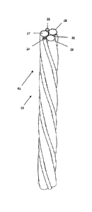
lowering the pipe in section.
[0009] This conventional method of lowering a high flow pipe and pump into a
bore
requires a crane to suspend and support the high flow pipe and pump using
chain. A
crane is required due to the size and weight of the required high flow pipe.
To meet
site requirements, technicians and a safety supervisor are required to be on
site
each time operations to lower and operate or raise the pumping assembly are
conducted. An electricity cord travels down the side of the high flow pipe and
the
AMENDED SHEET
IPEA/AU
3
CA 02895566 2015-06-18
PCT/AU2013/001502
ReceivecE8/02/2014
pump to power the pump. The high flow pipe can be a large diameter flexible
pipe,
connected to pump to direct the pumped fluid to a desired location.
[0010] The coupling, lowering and raising of pipes is time consuming and
requires a
team of technicians, safety supervisors as well as multiple pieces of
equipment. It
also places the technicians and supervisors in direct danger as they must
physically
interact with the suspended pipe to raise, lower and couple them.
[0011] Where conventional test pumping is undertaken, a submersible pump, an
electric cable, a stainless steel security cable, a monitoring tube and a
rising/delivery
pipe are lowered down a water containing bore/well. When different flow rates
are
required for different testing applications pipes of different diameters
coupled with
pumps of different capacity are required to be placed in the bore. Raising and
lowering of the test pump is required each time a different diameter pipe or
different
flow pump is needed. This involves a crane, suspended loads and technicians
every
time, costing money and placing the technicians at risk. The time taken to
raise or
lower the pipe, connecting or disconnecting the straight lengths with the aid
of a
crane can take hours.
[0012] The preceding discussion of the background art is intended to
facilitate an
understanding of the present invention only. The discussion is not an
acknowledgement or admission that any of the material referred to is or was
part of
the common general knowledge as at the priority date of the application.
[0013] The preceding discussion of the background art is intended to
facilitate an
understanding of the present invention only. The discussion is not an
acknowledgement or admission that any of the material referred to is or was
part of
the common general knowledge as at the priority date of the application.
SUMMARY OF INVENTION
[0014] It is an object of this invention to ameliorate, mitigate or overcome,
at least
one disadvantage of the prior art, or which will at least provide the public
with a
practical choice.
AMENDED SHEET
IPEA/AU
4
CA 02895566 2015-06-18
PCT/AU2013/001502
ReceivecE8/02/2014
[0015] In a first aspect, the present invention provides a conduit for pumping
fluid
from an external reservoir such as a bore comprising a plurality of pipes,
wherein the
pipes are uniformly entwined together along their length to provide multiple
fluid
passageways; wherein the conduit is to be wound onto a reel and off the reel
repeatedly.
[0016] The uniform entwinement ensures that fluid travelling through each of
the
plurality of pipes travels at the same rate through the grouped entwined pipe.
The
multiple fluid passageways ensure that the conduit transports more fluid than
any of
the individual plurality of pipes.
[0017] Preferably, the conduit is adapted to be wound onto a reel and the reel
is
adapted to be transported on a truck.
[0018] The reeling of the conduit and its transportability increase the ease
with which
the conduit can be used in different locations for different applications.
[0019] Preferably, the conduit transports a greater volume of fluid than the
individual
pipes, wherein the individual pipes do not collapse when wound onto the reel,
and
wherein each pipe is adapted to transport fluid from one end of the conduit to
the
other end at the same rate.
[0020] In not being collapsible, the life span of the individual pipes is
increased.
[0021] Preferably, each of the pipes is selectively closable.
[0022] By being selectively closable, different flows can be achieved through
the
conduit.
[0023] Preferably, the plurality of pipes are adapted to be operatively
connected to a
pump, and wherein the pump is adapted to be lowered into, and pump from, a
bore.
[0024] Each pipe may be adapted to transport fluid from one end of the grouped
entwined pipe to the other end at the same rate. This ensures that the grouped
entwined pipe operates as if it were a pipe having a larger diameter but with
the
added flexibility of coiling at a smaller diameter.
[0025] Each pipe in the grouped entwined pipe may be equal in length.
AMENDED SHEET
IPEA/AU
5
CA 02895566 2015-06-18
PCT/AU2013/001502
ReceivecE8/02/2014
[0026] The plurality of pipes may be entwined by twisting the pipes relative
to each
other about a central axis of the grouped entwined pipe. This allows the
individual
pipes of the grouped entwined pipe to be of the same length but still be
coiled.
[0027] In another aspect of the invention the plurality of pipes may be
entwined by
braiding the pipes together.
[0028] In a yet a further aspect of the invention the plurality of pipes may
be entwined
by plaiting the pipes together.
[0029] Each of the plurality of pipes may be of different diameter.
[0030] The pipes may be retained in the entwined arrangement with engagement
means. The engagement means maintains the entwinement and shape of the
grouped entwined pipe.
[0031] The engagement means may be shrink wrap adapted to enclose the grouped
entwined pipe.
[0032] The engagement means may be cable ties adapted to enclose the grouped
entwined pipe.
[0033] The engagement means may be a manifold adapted to engage the plurality
of
pipes.
[0034] The grouped entwined pipe may be adapted to transport greater than 801
per
second.
[0035] Each of the plurality of pipes may have a diameter of at least 90mm.
[0036] The grouped entwined pipe may be operatively connected to a pump. The
pump can be a submersible pump.
[0037] Each of the pipes may be selectively closable. This allows variable
flow rates
to pass through the grouped entwined pipe with only selected pipes
transporting
fluid.
[0038] Each pipe may include at least one valve adapted to selectively close
the pipe
that it is associated with.
AMENDED SHEET
IPEA/AU
6
CA 02895566 2015-06-18
PCT/AU2013/001502
ReceivecE8/02/2014
[0039] Each pipe at an end of the grouped entwined pipe may engage a manifold.
[0040] The manifold may secure the end of each pipe relative to each other.
The
manifold may be adapted to couple with other pipes or machinery.
[0041] The grouped entwined pipe may be over 100m long.
[0042] In a further aspect of the present invention, there is provided a
method of
installing, operating and withdrawing a transportable high flow downhole
pumping
assembly from a bore, including positioning the downhole pumping assembly
around
the bore, unwinding a reeled high flow fluid passageway and lowering it into
the
bore, pumping fluid from the bore, ceasing pumping, winding the high flow
fluid
passageway onto the reel to raise and withdraw the fluid passageway from the
bore;
wherein the high flow fluid passageway comprising a plurality of pipes for
pumping
fluid from the bore, wherein the pipes are uniformly entwined together along
their
length to provide multiple fluid passageways.
[0043] This method allows a downhole pumping assembly to be used on a bore
without the need of a technical team and safety team accompanied by cranes.
[0044] The method may include the steps of moving the reeled non-collapsed
fluid
passageway into an installation condition, unwinding the fluid passageway and
lowering it into the bore, positioning the reeled fluid passageway into an
operating
condition and pumping fluid from the bore, ceasing pumping, positioning the
reeled
fluid passageway into the installation condition winding the fluid passageway
onto
the reel to raise and withdraw the fluid passageway from the bore.
[0045] The fluid passageway may be the conduit comprising a plurality of
pipes.
[0046] The installation condition may be an upright position.
[0047] The installation and operating conditions may be the same position.
[0048] A motorized driving device may be used to wind and unwind the fluid
passageway.
[0049] The method may include pumping fluid through the fluid passageway at a
rate
of 70I/s or greater.
AMENDED SHEET
IPEA/AU
7
CA 02895566 2015-06-18
PCT/AU2013/001502
ReceivecE8/02/2014
[0050] In yet a further aspect, the present invention provides a downhole
pumping
assembly adapted to pump fluid from an external fluid reservoir including, a
conduit
comprising a plurality of pipes for pumping fluid from the fluid reservoir,
the conduit
having a high flow rate capacity, a reel, upon which the fluid passageway may
be
wound without collapsing, the reel being rotatably mounted, a pump for pumping
fluid
through the fluid passageway, and a driving means to lower and raise the fluid
passageway relative to the bore.
[0051] The downhole pumping assembly may include a mast to which the reel is
rotatably mounted, wherein the mast is moveable between an installation
condition
and an operating condition. The mast positions the reel so that the fluid
passageway
can be lowered and operated in the bore.
[0052] The installation condition may position the mast in an upright
position.
[0053] The installation and operating conditions may be the same position.
[0054] The operating condition may position the mast at an angle with respect
to the
vertical.
[0055] Preferably, the method is performed from a transportable platform. This
enables the assembly to be moved between different bores where the method can
be applied. By performing the method on a transportable platform, the assembly
can
be transported to the bore site and deployed and brought into operation
quickly with
minimal supervision.
[0056] The transportable platform may be the tray of a truck. This enables the
assembly to be moved between sites using a truck.
[0057] In another aspect, the present invention provides a method of
installing,
operating and withdrawing from a bore a high flow downhole pumping assembly
located on a transportation vehicle, including positioning the transportation
vehicle
around the bore, moving the reeled non-collapsed fluid passageway into an
installation condition, unwinding the fluid passageway from the reel and
lowering it
into the bore, positioning the reeled fluid passageway into an operating
condition and
pumping fluid from the bore, ceasing pumping, positioning the reeled fluid
AMENDED SHEET
IPEA/AU
8
CA 02895566 2015-06-18
PCT/AU2013/001502
ReceivecE8/02/2014
passageway into the installation condition winding the fluid passageway onto
the reel
to raise and withdraw the fluid passageway from the bore. This method allows a
downhole pumping assembly to be used on a bore without the need of a technical
team and safety team accompanied by cranes.
[0058] This method allows a downhole pumping assembly to be used on a bore
without the need of a technical team and safety team accompanied by cranes.
[0059] The downhole pumping assembly may include a mast to which the reel is
rotatably mounted, wherein the mast is moveable between an installation
condition
and an operating condition. The mast positions the reel so that the fluid
passageway
can be lowered and operated in the bore.
[0060] The installation condition may position the mast in an upright
position.
[0061] The installation condition and the operating condition may be the same
position.
[0062] The operating condition may position the mast at an angle with respect
to the
vertical.
[0063] The reel may rest on a surface of the transportation vehicle in the
operating
condition.
[0064] In one aspect of the invention the fluid passageway is in the form of a
single
pipe.
[0065] In another aspect of the invention the fluid passageway is in the form
of a pipe
comprising a plurality of entwined individual pipes. The entwined pipes help
to
enable the reelability of the high flow pipe.
[0066] The downhole pumping assembly may pump fluid through the fluid passage
way at a rate of 70I/s or greater.
[0067] The present invention further provides a method of installing,
operating and
withdrawing a transportable high flow downhole pumping assembly relative to a
bore
the assembly being located on a vehicle and movable between an operating
condition and an installation condition, the method comprising:
AMENDED SHEET
IPEA/AU
9
CA 02895566 2015-06-18
PCT/AU2013/001502
ReceivecE8/02/2014
positioning the assembly relative to the bore such that a fluid passageway of
the
assembly may be received in the bore;
activating a drive means to cause the fluid passageway to be lowered into the
bore
the required depth;
activating a pump to pump fluid from the bore through the fluid passageway.
[0068] Preferably the assembly is moved from the operating condition to the
installation condition after the assembly is positioned relative to the bore.
[0069] Preferably, after lowering the fluid passageway into the bore the
assembly is
moved from the installation position to the operating condition prior to
activating the
pump.
[0070] When activating the drive means the drive means may cause a reel to
rotate
such that the fluid passageway unwinds from the reel as it is lowered into the
bore.
[0071] Preferably the pump may be regulated to adjust the flow rate without
the need
to remove the fluid passageway from the bore.
[0072] Once the pumping is complete the assembly may be moved to the
installation
condition and the fluid passageway may be wound back on to the reel.
[0073] In yet a further aspect, the present invention provides a transportable
downhole pumping assembly for pumping fluid from a bore including, a fluid
passageway having a high flow rate capacity, a reel, upon which the fluid
passageway may be wound, the reel being rotatably mounted to a supporting
frame,
a pump for pumping fluid through the fluid passageway, and a driving means to
lower and raise the fluid passageway relative to the bore. The high flow fluid
passageway allows for fast and safe operation of the assembly.
[0074] In one aspect of the invention the fluid passageway is in the form of a
single
pipe.
AMENDED SHEET
IPEA/AU
10
CA 02895566 2015-06-18
PCT/AU2013/001502
ReceivecE8/02/2014
[0075] In another aspect of the invention the fluid passageway is in the form
of a pipe
comprising a plurality of entwined individual pipes. The entwined pipes help
to
enable the reelability of the high flow pipe.
[0076] The driving means may be a motor.
[0077] The driving means may be remotely operable. The remote operation
reduces
the man power required and increases safety.
[0078] The pump may be remotely operable.
[0079] The pump may include a variable speed drive to enable pumping of
different
flow rates.
[0080] Preferably the downhole pumping assembly is located no more than 3m
above ground level. This means that the operation of the assembly is not at a
height
that requires cranes and suspended loads, hence reducing required safety
precautions.
[0081] The downhole pumping assembly may be adapted to be transported on the
back of a truck. This allows the easy positioning of the pipe.
[0082] The downhole pumping assembly may be adapted to operate on the back of
a
truck. This allows easy, safe use of the reeled pipe and reduces the number of
people required during operation.
[0083] The downhole pumping assembly may include a mast to which the reel is
rotatably mounted, wherein the mast is moveable between an installation
condition
and an operating condition. The mast enables the reel to be located and allows
the
fluid passageway to be installed relative to the bore in a safe manner.
[0084] The pipe may be lowered into a bore hole when the mast is in the
installation
condition.
[0085] The pipe may transport fluid when the mast is in the operating
condition.
AMENDED SHEET
IPEA/AU
11
CA 02895566 2015-06-18
PCT/AU2013/001502
ReceivecE8/02/2014
[0086] The mast may be in an upright position when in the installation
condition. The
installation condition being upright ensures that gravity assists the
unwinding of the
fluid passageway in the maximum possible way.
[0087] The mast may be angled with respect to the vertical when in the
operating
condition. By moving the mast out of the vertical position, the mast is less
obtrusive
as it protrudes less from what the mast is attached to.
[0088] The fluid passageway may be capable of transporting fluid at 70I/s or
greater.
[0089] The pipe may include a submersible pump attachable to an end distal
from
the reel.
[0090] In still a further aspect of the present invention, there is provided a
downhole
pumping assembly located on the tray of a truck for pumping fluid from a bore
is
provided including, a fluid passageway having a high flow rate capacity, a
reel, upon
which the fluid passageway may be wound, the reel being rotatably mounted to a
supporting frame, a pump for pumping fluid through the fluid passageway, and a
driving means to lower and raise the fluid passageway relative to the bore,
wherein
the supporting frame is positionable into an installation condition from which
the fluid
passageway can be unwound to lower and rewound to raise, and an operating
condition from which the assembly can pump fluid, a pump for pumping fluid
through
the fluid passageway, and a driving means to lower and raise the fluid
passageway
relative to the bore. This high flow fluid passageway allows for fast and safe
operation of the assembly.
[0091] The installation condition and the operating condition may be the same
position.
[0092] The downhole pumping assembly may include a mast to which the reel is
rotatably mounted, wherein the mast is moveable between the installation
condition
and an operating condition. The mast enables the reel to be located and allows
the
fluid passageway to be installed relative to the bore in a safe manner.
[0093] The pipe may be capable of transporting fluid at 70I/s or greater.
AMENDED SHEET
IPEA/AU
12
CA 02895566 2015-06-18
PCT/AU2013/001502
ReceivecE8/02/2014
[0094] The pump may include a variable speed drive to enable pumping at
different
flow rates.
BRIEF DESCRIPTION OF THE DRAWINGS
[0095] Further features of the present invention are more fully described in
the
following description of several non-limiting embodiments thereof. This
description is
included solely for the purposes of exemplifying the present invention. It
should not
be understood as a restriction on the broad summary, disclosure or description
of the
invention as set out above. The description will be made with reference to the
accompanying drawings in which:
Figure 1 is a perspective view of a grouped entwined pipe according to a
second embodiment of the present invention;
Figure 2 is a cross sectional view of a grouped entwined pipe according to a
first embodiment of the present invention;
Figure 3 is a cross sectional view of the grouped entwined pipe if Figure 1;
Figure 4 is a cross sectional view of the grouped entwined pipe of Figure 1;
Figure 5 is a cross sectional view of a grouped entwined pipe according to a
third embodiment of the present invention;
Figure 6 is a perspective view of a manifold for use with the grouped entwined
pipe of Figure 5;
Figure 7 is a front view of a downhole pumping assembly according to a fourth
embodiment of the present invention;
Figure 8 is a perspective view of the downhole pumping assembly of Figure 7;
Figure 9 is a side view of the downhole pumping assembly of Figure 7;
Figure 10 is a front view of a downhole pumping assembly of Figure 7;
Figure 11 is a perspective view of the downhole pumping assembly of Figure
7;
AMENDED SHEET
IPEA/AU
13
CA 02895566 2015-06-18
PCT/AU2013/001502
ReceivecE8/02/2014
Figure 12 is a side view of the downhole pumping assembly of Figure 7;
Figure 13 is a perspective view of a downhole pumping assembly in
accordance with a fifth embodiment of the present invention;
Figure 14 is a perspective view of the downhole pumping assembly of Figure
13;
Figure 15 is a plan view of a downhole pumping in accordance with a sixth
embodiment of the present invention;
Figure 16 is a plan view of the downhole pumping assembly of Figure 15:
[0096] In the drawings like structures are referred to by like numerals
throughout the
several views. The drawings shown are not necessarily to scale, with emphasis
instead generally being placed upon illustrating the principles of the present
invention.
DESCRIPTION OF EMBODIMENTS OF THE INVENTION
[0097] The first, second and third embodiments of the present invention
provide a
conduit/grouped entwined pipe 61 made up of a plurality of individual pipes
entwined
with each other. The grouped entwined pipe then provides a flow capability
much
greater than that of the flow capability of the individual pipes making up the
plurality
of pipes. It also enables the grouped entwined pipe 61 to be wound onto a reel
without collapsing in on itself. The conduit/ grouped entwined pipe of the
present
invention is capable of being repeatedly wound onto and off a reel.
[0098] Referring to figure 2, the invention according to a first embodiment,
the
grouped entwined pipe is in the form of a conduit/grouped entwined pipe 11,
comprising two individual pipes 22, 23 entwined together with a power conduit
24
and minor conduits 25. This provides a pipe having two fluid passageways
through
individual pipes 22, 23. The grouped entwined pipe 11 provides flow
capabilities
equal to a much larger diameter pipe than each of the individual pipes 22, 23,
while
maintaining the ability to be wound onto a reel without collapsing. The
individual
pipes 22, 23 are twisted with respect to each other around the central axis of
the
AMENDED SHEET
IPEA/AU
CA 02895566 2015-06-18
14
PCT/AU2013/001502
ReceivecE8/02/2014
grouped entwined pipe 11. This twisting entwines the individual pipes 22, 23
in a
similar manner to that of the individual strands of a rope.
[0099] By entwining the pipes together, each individual pipe 22, 23 is
entwined
equally with respect to each other so that the length of each individual pipe
22, 23 is
the same between opposite ends of the grouped entwined pipe 11. This ensures
that fluid entering each of the individual pipes 22, 23 at one end of the
grouped
entwined pipe 11, will exit the other end of the grouped entwined pipe at the
same
time.
[00100] The entwinement of the individual pipes 22, 23 also ensures that
when
the grouped entwined pipe 11 is wound onto a reel there is no difference in
the
distance travelled around the reel by each individual pipe 22, 23. As each
pipe 22,
23 twists equally around the central axis of the grouped entwined pipe 11,
each pipe
22, 23 maintains the same mean diameter from the central axis of the grouped
entwined pipe.
[00101] Barlow's equation to calculate the bursting pressure for a pipe
recites:
P = (2*S*T)/( OD)
where P is the bursting pressure of the pipe,
S is the pipe's material strength,
T is the wall thickness of the pipe and
OD is the outside diameter.
From this it is known that pipes having a small outside diameter can withstand
a
greater internal pressure than a larger diameter pipe of the same wall
thickness.
Therefore, larger diameter pipes, which obviously have an increased flow
capacity,
require thicker walls in order to withstand the internal pressure. However, as
the wall
thickness increases the pipe becomes stiffer and is therefore more difficult
to wind
onto a reel. As the pipe stiffness is directly related to the diameter of the
pipe a large
AMENDED SHEET
IPEA/AU
15
CA 02895566 2015-06-18
PCT/AU2013/001502
ReceivecE8/02/2014
diameter pipe is more likely to collapse than small diameter pipes unless the
wall
thickness is substantially increased.
[00102] As the grouped entwined pipe 11 is made up of individual pipes 22, 23,
each individual pipe 22, 23 can have a smaller wall thickness than a single
large
diameter pipe having the same or similar flow capacity as the grouped entwined
pipe
11. With smaller diameters than an equivalent flow large pipe, the individual
pipes
22, 23 of the grouped entwined pipe 11 retain their ability to withstand a
higher
pressure, as well as to be rolled onto a reel without collapsing. The
individual pipes
22, 23 maintain these properties as part of the grouped entwined pipe 11 and
hence
effectively provide the equivalent volumetric flow of a larger diameter pipe
but which
can be wound onto a reel with minimal chance of collapsing.
[00103] Once the individual pipes 22, 23 have been twisted to form the grouped
entwined pipe 11, they are retained in the twisted arrangement by applying an
engagement means around the outside diameter of the grouped entwined pipe 11.
The engagement means (not shown) can be a layer of shrink wrap wrapped around
the outside diameter of the grouped entwined pipe 11 cable ties to lock the
individual
pipes 22, 23 together, an adhesive applied between the individual pipes, or
otherwise as understood by the skilled addressee. Additionally, the ends of
the
individual pipes 22, 23 may be held in position by a coupling manifold 21 such
as
that shown in Figure 6.
[00104] The power conduit 24 runs along the length of the grouped entwined
pipe
11. The power conduit 24 is used to transport electricity between devices at
either
end of the grouped entwined pipe 11. For example where the grouped entwined
pipe 11 is used to pump fluid, the power conduit 24 is used to supply
electricity to the
pump (not shown) at the end of the grouped entwined pipe 11. In another
example
where the grouped entwined pipe 11 is used on a travelling irrigation
sprinkler the
power conduit 24 is used to drive the movement of the traveling sprinkler and
pump
that supplies the grouped entwined pipe 11. Alternatively where water is used
to
drive the movement of the traveling sprinkler the power conduit 24 powers the
pump.
[00105] The minor conduits 25 are used to house sensors along the length of
the
grouped entwined pipe 11. For example, where the grouped entwined pipe 11 is
AMENDED SHEET
IPEA/AU
16
CA 02895566 2015-06-18
PCT/AU2013/001502
ReceivecE8/02/2014
used in a bore hole pumping arrangement with a submersible pump, the minor
cables carry pressure sensors. In this way when the water level in the bore
lowers
and approaches the pump, the pressure sensors are used to switch off the pump
to
avoid dry pumping and subsequent damage to the pump.
[00106] The power conduit 24 and minor conduits 25 can be attached to the
grouped entwined pipe 11, by being entwined with the individual pipes 22, 23
within
the shrink wrap, or ties may be used to hold the power conduit 24 and minor
cables
relative to the individual pipes 22, 23. In a varied arrangement, the power
conduit 24
can be attached by a separate tie or alternative attachment device.
[00107] In a varied arrangement, the power conduit 24 can be separate to the
grouped entwined pipes 11, or may be tied to only one of the individual pipes.
[00108] As the grouped entwined pipe 11 comprises more than one fluid
passageway, it is possible to alter the flow capacity of the grouped entwined
pipe 11
by blocking off one of the individual pipes 22, 23 to prevent, or restrict
flow
therethrough. Blocking one of the individual pipes 22, 23 with a valve(not
shown)
allows the flow to be regulated.
[00109] Figures 1, 3 and 4 illustrate a second embodiment of the present
invention. This embodiment is similar to the first embodiment and similar
features
have been given the same numbering. In this embodiment the grouped entwined
pipe is in the form of conduit/grouped entwined pipe 13 comprises three
individual
pipes 26, 27, 28 rather than the two pipes 22, 23 of the conduit/grouped
entwined
pipe 11 entwined together.
[00110] Entwinement of the individual pipes 26, 27, 28 of the grouped entwined
pipe 13 is achieved by twisting the individual pipes 26, 27, 28 like the
strands of a
rope relative to the central axis of the grouped entwined pipes 13 as
described in the
first embodiment. Grouped entwined pipe 13 uses 3 individual pipes 26, 27, 28.
This entwinement can be achieved by arranging the pipes straight and adjacent
each
other and then twisting the pipes together.
[00111] Alternative forms of entwinement, such as braiding or plaiting may be
used.
AMENDED SHEET
IPEA/AU
17
CA 02895566 2015-06-18
PCT/AU2013/001502
ReceivecE8/02/2014
[00112] Figure 4 illustrates the grouped entwined pipe 13 having pipe 28
blocked by
a valve 62. The flow rate through the grouped entwined pipe 13 is reduced by
blocking individual pipe 28 with valve 62, preventing the blocked pipe 28 from
transporting fluid.
[00113] In a varied embodiment, to facilitate flow regulation one of the
individual
pipes 26, 27, 28 is associated with a valve (not shown). When the grouped
entwined
pipe 13 is attached to a pump or other fluid supply means, each individual
pipe 26,
27, 28 within the grouped entwined pipe 13 is capable of transporting the
fluid.
[00114] The flow rate through the grouped entwined pipe 13 can be reduced by
one
third by closing valve 62. This allows the grouped twisted pipe 13 to perform
as a
selectively variable flow pipe.
[00115] Varying the flow rate is aided with the use of a variable flow pump at
the
end if the grouped entwined pipe 13.
[00116] Figure 5 illustrates a third embodiment of the present invention which
is
similar to the first and second embodiments and similar features have been
given the
same numbering. In this embodiment the grouped entwined pipe is in the form of
conduit/grouped entwined pipe 15 comprises four individual pipes 29, 30, 31,
32
entwined together.
[00117] Entwinement of the individual pipes 29, 30, 31, 32 of the grouped
entwined
pipe 15 is achieved by twisting the individual pipes 29, 30, 31, 32 like the
strands of
a rope around the central axis of the grouped entwined pipe 15 as described in
the
first and second embodiments. This grouped entwined pipe 15 is realised by
arranging the individual pipes 29, 30, 31, 32 straight against each other and
then
twisting the pipes together. Other methods of twisting can be used and a
varying
number of individual pipes can be used.
[00118] It is within the scope of the present invention for the first and
third
embodiments to include valves to vary the flow rate of the grouped entwined
pipe 11,
13 as described for the second embodiment.
AMENDED SHEET
IPEA/AU
18
CA 02895566 2015-06-18
PCT/AU2013/001502
ReceivecE8/02/2014
[00119] In varied embodiments of the first second and third versions of the
present
invention, the pipes 22, 23, 24, 26, 27, 28, 29, 30 ,31, 32 of the grouped
entwined
pipes 11, 13, 15 can be braided together.
[00120] Where a standard braiding technique is used to entwine the pipes 22,
23,
24, 26, 27, 28, 29, 30 ,31, 32 together to form one of grouped entwined pipe
11, 13,
15, the braiding technique results in the length of each individual pipe 22,
23, 24, 26,
27, 28, 29, 30 ,31, 32 being the same between opposite ends of the grouped
entwined pipe 11, 13, 15, resulting in the beneficial characteristics
discussed above
with respect to the previous embodiments. Alternative entwinement methods are
envisaged by the present invention, including plaiting, twisting or otherwise.
[00121] Although the above embodiments consider the grouped entwined pipe 61
as grouped entwined pipes 11, 13 and 15 with 2, 3 and 4 pipes, it is within
the scope
of the present invention to use more than four pipes to form the grouped
entwined
pipe in the manner as described for the first, second and third embodiments of
the
present invention.
[00122] Figure 6 shows a coupling manifold 21 which may be used to connect the
pipes of grouped entwined pipe 15 to another device.
[00123] The manifold 21 may connect the grouped entwined pipe 15 to a pump, a
travelling irrigation sprayer, a reservoir, other piping or other devices
which may be
used in high flow pumping. For ease of connection the manifold 21 can be
arranged
for quick engagement and quick release. The manifold is illustrated for use
with the
four pipe 29, 30, 31, 32 embodiment of grouped pipe 15. Each of the individual
pipes 29, 30, 31, 32 are received and then lockingly engaged with one of the
protrusions 94, 95, 96, 97. It is readily recognized that the manifold 21 can
be
configured to connect any number of pipes with an alternate number of
protrusions.
[00124] It is readily recognisable that any number of the individual pipes in
a
grouped entwined pipe can be blocked with a valve as desired by the pipe user.
This allows the grouped twisted pipe to perform as a selectively variable flow
pipe.
[00125] Valves used to block pipes and control the flow of the grouped
entwined
pipe can be placed at either end of each individual pipe in the grouped
entwined
AMENDED SHEET
IPEA/AU
19
CA 02895566 2015-06-18
PCT/AU2013/001502
ReceivecE8/02/2014
pipe. Then each individual pipe, can be shut off using a variety of typical
valve
arrangements readily understood by the skilled addressee. The shut off valves
can
be located in the manifold 21 or along the length of the individual pipes. The
shut off
valves can be used with a variable flow pump.
[00126] The individual pipes of the grouped entwined pipes 11, 13, 15 are made
of
a material that is suitable to be repeatedly wound onto and off a reel. One
example
is a high density polyethylene (HDPE) pipe. Alternatives materials, suitable
for
winding onto and from a reel, as would be understood by the skilled addressee
can
be used.
[00127] A HDPE pipe can typically be coiled onto a reel provided that the reel
has
an inside diameter at least 20 times greater than the diameter of the pipe. In
a first
example, a single 140mm HDPE pipe (polyethylene) capable of providing a flow
of
80I/s requires a reel with an inside diameter of 2.8m. Such a reel is too
large to
transport on a road without oversize load escorts and requires additional
safety
provisions. However, if instead the grouped entwined pipe 13 comprising three
90mm HDPE pipes entwined together as per the present invention was used, the
reel will require an inside diameter of 1.8m. Once wound onto the reel, the
reel will
be 3.4m in diameter, 2.4m wide, carry nearly 500m of 90mm grouped entwined
pipe,
and is capable of providing higher flow rates, maintain a higher pressure
rating and
have walls of the same or smaller thickness than the 140 single pipe.
[00128] A grouped entwined pipe 61 (that could be any of the grouped entwined
pipes 11, 13, 15) of the present invention is ideal for use in pumping bores.
A reeled
entwined grouped pipe can be lowered into a bore with a pump attached to one
of its
ends. A grouped entwined pipe 13 comprising three 90mm individual pipes can
achieve a fluid flow of 80 litres per second and higher. By using the grouped
entwined pipe 13, the need to connect straight lengths of larger diameter pipe
while
the pipe is being lowered into the bore as discussed in the background section
is
removed and the reeled grouped entwined pipe 13 can simply be lowered into the
bore from the reel. The reeled entwined grouped pipe 13 can be lowered into,
or
raised from a bore in a fraction of the time required to raise and lower a
pipe that is
in sections. Furthermore it removes the need to use a crane to lower the pipe.
AMENDED SHEET
IPEA/AU
20
CA 02895566 2015-06-18
PCT/AU2013/001502
ReceivecE8/02/2014
[00129] Another application of the use of the entwined grouped pipe 61 is with
self
travelling irrigation sprinklers. Long rolls of entwined grouped pipe on large
reels can
be used to supply a self travelling irrigation system. The length of the
entwined
grouped pipe of the present invention on the reels can now be up to 700 or
800m
long or longer. Where the grouped entwined pipe comprises individual pipes of
90mm diameter, a longer travel length is achievable than with a 140mm single
pipe.
Also, advantageously the grouped entwined pipe 61 of 90mm individual pipes can
be
reeled and transported on the back of a truck un-escorted.
[00130] An additional example uses the entwined grouped pipe 61 in a test
pumping situation. The entwined group pipe is placed in the test fluid and the
valves
are selectively shut off to achieve the desired flow rate with the use of a
variable flow
pump in combination with a variable speed drive to achieve a wide range of
flows
from a single submersible pump, without loss of data. The variable flow pump
is
lowered into the fluid to be tested and different desired flows from the fluid
source
can be achieved by opening and closing the valves at different pump settings
without
the need to withdraw and change the pipe and pump used.
[00131] Figures 7 to 16 illustrate a downhole pumping assembly 90, 91
including
reels 50, 51 according to further embodiments of the present invention, where
the
reels 50, 51 are suited to hold and carry a grouped entwined pipe 61. As noted
above, the grouped entwined pipe 61 may be in the form of any of grouped
entwined
pipes 11, 13, 15 (in addition to one with more than 4 individual pipes) and is
adapted
to be wound on and off a reel 50, 51 repeatedly into a bore hole, mine, or
other
passageway.
[00132] With particular reference to Figures 7 to 12, illustrating the fourth
embodiment of the present invention, the downhole pumping assembly 90 includes
a
mast 34 fixed to frame 70 for support. The frame 70 includes a base 170 and
uprights 171. The frame 70 is adapted to sit on a support means above the bore
hole, mine or other passageway as required. The reel 50 is rotatably mounted
onto
mast 34 about pin 55. The mast 34 moves the reel between a stored condition as
shown in Figures 7, 8 and 9 and an installation condition as shown in Figures
10, 11
and 12 which will be described below in further detail. The mast 34 includes
an
AMENDED SHEET
IPEA/AU
21
CA 02895566 2015-06-18
PCT/AU2013/001502
ReceivecE8/02/2014
extension arm 44 and a supporting arm 46. The pin 55 is located along the
supporting arm 46.
[00133] Alternatively, the frame uprights 171 of the frame 70 can extend
downwards to raise the base 170 and support the frame on plates 172. In this
arrangement the frame 70 supports itself over the bore hole, mine or
passageway.
[00134] Figures 7 to 9 illustrate the mast 34 and reel 50 placing the downhole
assembly 90 in the stored position. The mast 34 is fixed to the frame 70 at
pivot
hinge 80 and actuator pivot hinge 81. In the stored position, the hydraulic
actuator
82 is retracted causing the mast 34 and reel 50 to be lowered against the
frame 70.
To enable this, the mast 34 pivots around pivot hinge 80 to angle the mast
into a
lowered position. This minimizes the height of the downhole assembly 90
increasing
the ease with which the downhole assembly can be transported.
[00135] Figures 10 to 12 illustrate the mast 34 and reel 50 placing the
downhole
assembly 90 upright into the installation position. The mast 34 is fixed to
the frame
70 at pivot hinge 80 and actuator pivot hinge 81. In the installation
position, the
hydraulic actuator 82 is extended causing the mast 34 and reel 50 to be raised
into
an upright position.
[00136] When in the installation position, a drive means such as a motor is
used to
wind the reel 50 and lower or raise the grouped entwined pipe 61 into or from
the
bore hole, mine or passageway.
[00137] The hydraulic actuator 82 and the drive means are controlled through
electronic control means such as a PLC, or otherwise as would be understood by
the
skilled addressee. The PLC or other control means is located on the downhole
assembly 90. Alternatively the PLC or other control means is remote control.
[00138] In the fourth embodiment, the grouped entwined pipe 61 (not shown in
Figures 7 to 12) carries fluid at a flow rate of 80I/s or greater and is able
to be wound
onto a reel repeatedly without collapsing on itself. To achieve the flow of
80I/s or
greater, the individual pipes of the group of entwined pipe 61 have an
internal
diameter of at least 80mm. The individual pipes of the group of entwined pipe
61 act
AMENDED SHEET
IPEA/AU
22
CA 02895566 2015-06-18
PCT/AU2013/001502
ReceivecE8/02/2014
together to transport fluid and collectively achieve the desired flow rate.
The
entwinement of the pipes to form the grouped entwined pipe 61 ensures that the
length of each individual pipe along the length of entwined pipe 61 is equal
and that
fluid travelling through the pipes travels the same distance and enters and
exits the
grouped entwined pipe 61 at the same time. By entwining smaller diameter pipes
to
form the grouped entwined pipe 61, the pipe 61 will not collapse when reeled
as
would happen with a pipe of larger diameter, capable of supporting the flow of
grouped entwined pipe 61. This is due to larger diameter pipes having a lesser
stiffness than smaller diameter pipes of the same wall thickness.
[00139] It is within the scope of the present invention for the flow rate to
be varied
from 80I/s as would be understood by the skilled addressee.
[00140] Figures 13 and 14 illustrate a fifth embodiment of the present
invention.
The fifth embodiment is similar to that of the fourth embodiment. The downhole
pumping assembly 91 is mounted to a frame 71. The frame is mounted on a tray
of
a truck 140. As in the fourth embodiment, the reel 51 is rotatably mounted
onto mast
134 about pin 155. The mast 134 moves the reel between a stored condition as
shown in Figure 14 and an installation condition as shown in Figure 13. The
mast
134 includes an extension arm 144 and a supporting arm 146. The pin 155 is
located along the supporting arm 146.
[00141] The mast 134 is fixed to the frame 71 along the base of the frame 71.
The
mast 134 moves between the stored position and the installation position at
pivot
hinge 180 and actuator pivot hinge 181. In the stored position of Figure 14,
the
hydraulic actuator 182 is retracted causing the mast 134 and reel 51 to be
lowered
against the frame 71. The hydraulic actuator 182 is mounted to the frame 71.
[00142] In the installation position of Figure 13, the hydraulic actuator
182 is
extended causing the mast 134 and reel 51 to be raised into an upright
position.
[00143] Figures 15 and 16 illustrate the fifth embodiment of the present
invention
including a grouped entwined pipe 61 wound onto the reel 51, where the
downhole
pumping arrangement 91 is mounted on the tray 140 of a truck 240. In Figure 16
the
mast 34 is shown in the stored position where it is at an angle to the
vertical and
AMENDED SHEET
IPEA/AU
23
CA 02895566 2015-06-18
PCT/AU2013/001502
ReceivecE8/02/2014
rests on the tray 140 of the truck 240. In this embodiment the mast 34 is also
place
in the operating condition when the reel 51 is to be transported.
[00144] In Figure 16 the mast 134 is shown in the installation condition
whereby
the mast 134 is in a generally upright position. The hydraulic arm 138
attached to
the tray of the truck selectively moves the mast 134 and reel 51 between the
angled
operating condition and the installation condition. When in the installation
condition
a support leg 142 is extended from the tray of the truck 240 to ensure that
the body
of the truck 240 is supported and does not overbalance.
[00145] The reel 51 is placed in the stored condition as shown in Figure 15 to
transport the downhole pump assembly 91. The downhole pump assembly 91 can
also be placed in the stored position once the grouped entwined pipe 61 has
been
unwound from the reel 51 in the installation position and then pump the bore
in the
stored position.
[00146] Although mast 134 is illustrated as raising the reel 51, it is readily
understood that alternative frames can be used to raise the reel 51 in a
manner
which will allow the reel 51 to rotate. It is to be understood that the mast
134 and
reel 51 or alternative frame need not be mounted on a truck and can be located
at
the site of the bore hole 300 where the grouped entwined pipe 61 is to be
deployed.
[00147] In operation, the truck 240 is positioned correctly about the bore
300.
When in position, the hydraulic arm 138 extends and raises the mast 134 into
the
upright position to be in the installation position. When in the upright
position, the
drive means, in the form of motor 160, is activated to rotate the reel 51 so
that
grouped entwined pipe 61 is unwound and the pump 140, which is fixed on the
distal
end of the grouped entwined pipe 61, is lowered into the bore 300. The grouped
entwined pipe 61 supports the weight of the pump 140. An electricity cable
(not
shown) powers the pump 140 and is lowered with the grouped entwined pipe 61.
[00148] The motor 160 to drive the reel 51 is illustrated in Figures 15 and 16
as
being powered by a generator and fuel, both of which are transported with the
truck
240. The generator and fuel can be of a conventional hydrocarbon burning
generator, can be solar assisted or otherwise. The generator and fuel can be
AMENDED SHEET
IPEA/AU
24
CA 02895566 2015-06-18
PCT/AU2013/001502
ReceivecE8/02/2014
transported with the truck 240 or alternatively can be located at the site of
the bore
300.
[00149] Although a hydraulic arm 138 is illustrated as moving the mast 134, it
is
recognized that a pivoting arm arrangement or other mechanical actuator can be
used to move the mast 134. Additionally it is recognised that instead of
rotating the
mast 134, a translation action can position the mast 134 in a variety of
positions
appropriate for transportation, lowering and pumping the downhole pumping
assembly 91.
[00150] The downhole pump assembly 91 can be skid mounted so that at the site
of operation, the downhole pump assembly 91 can be lifted from a
transportation
vehicle such as the truck 240, or another vehicle and placed on a frame at the
site
for operation as discussed above.
[00151] Once the truck 240 is correctly positioned (or once the downhole pump
assembly 30 has been removed from the truck 240 or other vehicle and placed on
a
positioned frame) the operation of the motor to turn the reel and lower the
pipe 32
and electrical cable, and then to activate the pump 40 can be switched on. An
operator need only switch the motor on and off at appropriate times to lower
the pipe
32 to the appropriate depth and then activate the pump 40 for the required
time.
With current wireless technologies this can be done remotely and the presence
of a
technician is only required to position the pipe 32 and reel 48 correctly.
[00152] The use of sensors can be employed so that there is no direct input
from
a technician at all. This removes the need for cranes, suspended loads,
straight
lengths of heavy, large diameter pipe and the need to join the pipe. The motor
assisted raising or lowering of the grouped entwined pipe 61 onto or from the
reel 51
can take as little as 10 minutes. Also as there is no need for a technician to
operate
the pumps, night pumping can be autonomously undertaken.
[00153] The individual pipes of the grouped entwined pipe 61 can be
selectively
closed to regulate the flow through the grouped entwined pipe 61, and
different
pump settings can be used accordingly. When a variable flow pump the
arrangement of the grouped entwined pipe 61negates the no need to change pipes
of different diameter and pumps of different capacity for different
applications and
AMENDED SHEET
IPEA/AU
25
CA 02895566 2015-06-18
PCT/AU2013/001502
ReceivecE8/02/2014
required flows. Instead individual pipes may be closed or opened to regulate
the
flow there through. As a result, the grouped entwined pipe 61 may be caused to
perform as a pipe of smaller diameter. These functions can also be operated
remotely.
[00154] With the use of a variable speed pump and grouped entwined pipe 61,
the
need to change pumps 140 between different diameter individual pipes is
removed.
With the removal of the need to change pumps, a variable speed pump can be
connected to an entwined group of pipes and the two can operate together for
the
operating lifespan of either the grouped entwined pipe 61 or the pump 40. With
a
grouped entwined pipe 61 and pump 140 that can operate at different flows,
there is
no need to change the pump 140 on the grouped entwined pipe 61, and the two
can
remain joined for the life of either the pump 140 or the grouped entwined pipe
61.
[00155] To operate the downhole pumping assembly 91, the truck 240 is driven
into position about the bore hole 300. When in position, the mast 134 is
raised into
the installation condition and the motor 160 activates to unwind the grouped
entwined pipe 61. When the grouped entwined pipe 61 reaches the desired
position
the unwinding ceases and the mast 134 is lowered into the operating condition
and
the pump 140 initiates pumping. When pumping is complete, the mast 134 is
raised
again into the installation condition and the motor 160 operates to raise the
grouped
entwined pipe 61 from the bore 300, winding it onto the reel 51.
[00156] It is within the scope of the present invention for the downhole
pumping
assembly 90, 91 to be located on a frame and not include a mast. In this
arrangement, the frame is placed over the bore hole, mine or passageway and
then
lower the grouped entwined pipe into the bore hole, mine or passageway without
being raised on a mast.
[00157] Modifications and variations such as would be apparent to the skilled
addressee are considered to fall within the scope of the present invention.
The
present invention is not to be limited in scope by any of the specific
embodiments
described herein. These embodiments are intended for the purpose of
exemplification only. Functionally equivalent products, formulations and
methods
are clearly within the scope of the invention as described herein.
AMENDED SHEET
IPEA/AU
26
CA 02895566 2015-06-18
PCT/AU2013/001502
ReceivecE8/02/2014
[00158] Reference to positional descriptions, such as lower and upper, are to
be
taken in context of the embodiments depicted in the figures, and are not to be
taken
as limiting the invention to the literal interpretation of the term but rather
as would be
understood by the skilled addressee.
[00159] Throughout this specification, unless the context requires otherwise,
the
word "comprise" or variations such as "comprises" or "comprising", will be
understood to imply the inclusion of a stated integer or group of integers but
not the
exclusion of any other integer or group of integers.
AMENDED SHEET
IPEA/AU