Note: Descriptions are shown in the official language in which they were submitted.
CA 02895611 2015-06-18
WO 2014/108534 PCT/EP2014/050477
1
METHOD FOR PACKING, PACKAGING MACHINE, COMPUTER PROGRAM,
AND PACKAGE
Technical field
The present invention generally relates to a method for packing a
container, a packaging machine for packing such a container, a computer
program for controlling such a packaging machine, and a package.
Background
Medical products, such as medical fluid containers, are sometimes
packed with an overwrap. Proper marking of the products is important.
However, sometimes the marking is subject to wear during transportation and
other handling. Information can in such cases get lost, wherein the product
cannot be used for security reasons.
It is therefore a desire to provide marking of such products where the
marking is more resistant to wear.
Summary
An object of the invention is to at least alleviate the above stated
problem. The present invention is based on the understanding that printing the
information on the inside of the overwrap protects it from wear.
According to a first aspect, there is provided a method for packing a
container. The method comprises feeding a first film; printing information on
the
first film; feeding a second film, wherein the first and second films encloses
a
container to be packed; evacuating air between the first and second films and
the container at sealing; and sealing the first and second films together
along a
line encircling the container to form a package. The printing of information
comprises printing information configured for the container to be packed, and
the printing is performed on a side of the first film becoming the inside of
the
package. The printing is performed as mirrored information on the side
becoming the inside of the package such that the printed information is
readable through the first film. The container is a bag and encloses a liquid
content.
CA 02895611 2015-06-18
WO 2014/108534 PCT/EP2014/050477
2
The printing may be performed as inverted information on the side
becoming the inside of the package. The printing may be arranged to provide
light absorbing or light reflecting print.
At least one of the first and second film may be transparent. At least
one of the first and second film may comprise a polymer, preferably, the
polymer is selected from polyvinyl chloride (PVC), polyolefin, polyester,
starch,
and cellulose, or mixtures thereof.
The method may further comprise thermoforming at least one of the first
and the second film. The thermoforming of the first film may be performed
after
the printing. The container may be placed on the second film after
thermoforming of the second film.
The printing position may be controlled by the occasion of a previous
sealing operation such that the print becomes positioned on a desired position
of the package. The printing position may be controlled by a feeding
mechanism. The printing position may be controlled by a feeding mechanism
being arranged between a printing module and sealing module. Alternatively, or
additionally, the printing position may be controlled by an actuating
mechanism
arranged to adjust the position of the printer. Alternatively, or
additionally, the
printing position may be controlled by time instant of the printing.
The sealing position may be controlled by a position of the print such
that the print becomes positioned on a desired position of the package.
The container placement on the second film may be synchronized with
the position of the print.
The printed information may be in form of any of: a barcode, a matrix
barcode, text, pictogram, or any combination thereof. The printed information
may be unique for each package.
The sealing may comprise any of: welding, gluing, heat sealing, or any
combination thereof.
According to a second aspect, there is provided a packaging machine
for packing a container. The machine comprises a first feeder constructively
arranged to feed a first film; a printer constructively arranged to print
information
on the first film; a second feeder constructively arranged to feed a second
film;
a packing mechanism constructively arranged to cause the first and second
films to enclose a container to be packed, wherein the container is a bag and
encloses a liquid content; an air evacuator constructively arranged to
evacuate
CA 02895611 2015-06-18
WO 2014/108534 PCT/EP2014/050477
3
air between the first and second films and the container at sealing; and a
controller constructively arranged to control operation of the machine. The
packing mechanism comprises a sealer mechanism constructively arranged to
close a package with a seal of the first and second films along a line
encircling
the container. The printer is controlled by the controller to print
information
configured for the container to be packed, and the printer is constructively
arranged on a side of the first film becoming the inside of the package. The
printer is controlled by the controller to print information as mirrored
information
such that the printed information is readable through the first film.
The machine may further comprise a thermoforming station
constructively arranged to thermoform at least one of the first and second
films.
The thermoforming station may be arranged such that thermoforming of the first
film is performed downstream of the printer.
The machine may comprise a container feeder mechanism
constructively arranged to place containers on the second film downstream of
the thermoforming station.
The printer may be controlled by the controller to print information as
mirrored information.
The printer may be constructively arranged to print the information in
form of any of: a barcode, a matrix barcode, text, pictogram, or any
combination
thereof.
The machine may further comprise an air evacuator constructively
arranged to evacuate air between the first and second films and the container
at
sealing.
The printing position may be controlled by the controller by the occasion
of a previous sealing operation such that the print becomes positioned on a
desired position of the package. The printing position may be controlled by
the
controller by controlling a feeding mechanism arranged between the printer and
sealer mechanism. Alternatively, or additionally, the printing position may be
controlled by an actuating mechanism arranged to adjust the position of the
printer. Alternatively or additionally the printing position may be controlled
by
time instant of the printing.
The sealing position performed by the sealer mechanism may be
controlled by the controller from a position of the print such that the print
becomes positioned on a desired position of the package.
4
The machine may comprise a container feeder mechanism controlled
by the controller to place containers on the second film synchronized with the
position of the print.
The sealer mechanism may be constructively arranged to seal the first
and second films by any of: welding, gluing, heat sealing, or any combination
thereof.
According to a third aspect, there is provided a computer readable
medium comprising computer program code, for a controller of a packaging
machine. The computer program code includes computer executable
instructions, which computer program code, when downloaded and executed by
a processor of the controller, causes the controller to control the machine to
perform the method according to the first aspect.
According to a fourth aspect, there is provided a package for a
container, wherein the package is formed from a first and a second film being
evacuated from air between the first and second films and the container and
sealed by a seal of the first and second films along a line encircling the
container. The package comprises printed information which is configured for
the container to be packed and is printed on an inside of the first film. The
printing is performed as mirrored information on the side becoming the inside
of
the package such that the printed information is readable through the first
film.
The container is a bag with liquid content, and wherein the printed
information is
printed on a printing position of the inside of the first film determined by a
controller by controlling a time instant of the printing such that the printed
information becomes placed on the desired position of the package (126).
The container may be a bag, preferably a bag with liquid content. The
liquid content of the bag may comprise a medical solution, preferably any of a
group comprising dialysis fluid and water.
The printed information may be arranged in form of any of: a barcode, a
matrix barcode, text, pictogram, or any combination thereof.
The printed information may be a print arranged to provide light
reflecting fields. The printed information may be a print arranged to or be a
print
arranged to provide light absorbing fields. The printed information may also
be a
combination thereof.
The printed information may be configured for machine reading of the
print.
The printed information may either be inverted or be non-inverted.
The printed information may be mirrored information on the side
becoming the inside of the package.
CA 2895611 2020-02-20
CA 02895611 2015-06-18
WO 2014/108534
PCT/EP2014/050477
Other objectives, features and advantages of the present invention will
appear from the following detailed disclosure, from the attached dependent
claims as well as from the drawings. Generally, all terms used in the claims
are
to be interpreted according to their ordinary meaning in the technical field,
5 .. unless explicitly defined otherwise herein. All references to "a/an/the
[element,
device, component, means, step, etc]' are to be interpreted openly as
referring
to at least one instance of said element, device, component, means, step,
etc.,
unless explicitly stated otherwise. The steps of any method disclosed herein
do
not have to be performed in the exact order disclosed, unless explicitly
stated.
Brief description of the drawings
The above, as well as additional objects, features and advantages of
the present invention, will be better understood through the following
illustrative
and non-limiting detailed description of preferred embodiments of the present
invention, with reference to the appended drawings.
Fig 1 schematically illustrates a side view of a machine, according to
embodiments, for packaging containers.
Fig. 2 schematically illustrates a top view of the machine of Fig. 1 for
packaging containers, regarded along the path of the containers through the
machine.
Fig. 3 is a flow chart illustrating a method according to an embodiment.
Fig. 4 is a flow chart illustrating printing operations according to
embodiments.
Fig. 5 is a flow chart illustrating forming of the package according to
embodiments.
Fig. 6 is a flow chart illustrating synchronizing for packaging the
container according to embodiments.
Fig. 7 is a top view of a package according to an embodiment.
Fig. 8 is a side view of a package according to an embodiment.
Fig. 9 schematically illustrates a side view of a machine, according to
embodiments, for packaging containers.
Fig. 10 schematically illustrates a top view of the machine of Fig. 9 for
packaging containers, regarded along the path of the containers through the
machine.
CA 02895611 2015-06-18
WO 2014/108534 PCT/EP2014/050477
6
Fig. 11 schematically illustrates a computer-readable medium and a
processor on which a computer program held by the computer-readable
medium can be executed.
Detailed description
Fig. 1 schematically illustrates a side view of a machine 100, according
to embodiments, for packaging containers 102. Fig. 2 schematically illustrates
a
top view of the machine 100 of Fig. 1 regarded along the path of the
containers
through the machine. The machine 100 comprises a first feeder 104 arranged to
feed a first film 106. The first feeder 104 can comprise a roll of film which
can
provide controlled feed, e.g. by servo motors, or can passively feed by
keeping
a preferred stretch of the film as later stages of the machine pulls the film.
The machine 100 also comprises a printer 108 arranged to print
information on the first film 106. The printing operations will be further
demonstrated below.
The machine 100 also comprises a second feeder 110 arranged to feed
a second film 112. The two films 106, 112 will form the package. Thus, the
machine 100 comprises a packing mechanism 114 arranged to cause the first
and second films 106, 112 to enclose a container 102 to be packed.
The machine also comprises a controller 124 arranged to control
operation of the machine 100. Here, it should be noted that the controller 124
can comprise one or more controllers, and the illustration in Fig. 1 is only
schematic. For example, the printer 108 can comprise its own controller for
acquiring the information to be printed, and the printer 108 can also comprise
a
controller for controlling the position of the printing. Similar, the feeding
mechanisms, and also the other elements that will be demonstrated below can
have dedicated controllers for each function. Alternatively, two or more
functions can share controllers. Alternatively, or additionally, there can be
a
master controller. For example, the master controller can be logically
arranged
in hierarchy with controllers dedicated to specific functions.
The packing mechanism 114 comprises a sealer mechanism 116, 118
arranged to close a package 126 with a seal 120, 122 of the first and second
films 106, 112 along a line encircling the container 102. This can be made in
numerous ways, e.g. depending on the geometry of the package 126 to be
formed. For example, sealing in line with the path of the films 106, 112 can
be
CA 02895611 2015-06-18
WO 2014/108534 PCT/EP2014/050477
7
made continuously by a first sealing means 116 as the films pass while
transversal sealing is performed by a second sealing means 114 at each
occasion a transversal sealing position is at the second sealing means 114.
Alternatively, the entire sealing around the container 102 can be performed in
.. one step by the sealing means 114. The machine can also comprise an air
evacuator 115 arranged to evacuate air between the first and second films and
the container at sealing. The overwrap formed by the first and second films
106,
112 will then be assured to fit tight to the container. An advantage is that
reading of the printed information may be enhanced since the lack of air
.. between the container 102 and the first film 106 may make the printed area
flat,
and the ensured contact between the container 102 and the first film 106 at
the
printed area may enhance reflecting and/or absorbing properties of the print,
as
will be discussed below. Further advantages are that the content of the
container can be further protected, and that a damage of the package is easily
spotted before use of the content. The sealer mechanism 116, 118 can be
constructively arranged to seal the first and second films 106, 112 by for
example welding, gluing, heat sealing, or any combination thereof.
The printer 108 is controlled by the controller 124 to print information
configured for the container 102 to be packed. That is, information indicating
or
being linked to information about for example product identification, time and
date, batch number, and/or package number, etc. for the particular package or
batch of packages is printed. The date can be production date and/or expiry
date. The printing can be performed as heat printing, ink jet printing, laser
printing, or any other printing technique suitable for the film used. The
printing
.. can be configured for machine reading of the print, e.g. by scanning. Here,
the
print can be either arranged to provide light reflecting print or light
absorbing
print. For configuring to reflecting or absorbing print, the encoding of the
print,
e.g. of a (matrix) barcode, can be inverted or non-inverted to facilitate,
improve
or enable reading or scanning. For example, if liquid content of the
container, or
the container itself, is such that it provides poor reflection in the
wavelengths
used for scanning, it is preferable to use a light reflecting print, e.g. the
ink or
the print technique provides light reflection at the fields printed in at the
wavelengths used for the scanning, such that the scanner is provided with a
proper contrast between printed and non-printed fields, e.g. in a (matrix)
barcode. In another example, the liquid of the container, or the container
itself,
CA 02895611 2015-06-18
WO 2014/108534 PCT/EP2014/050477
8
is such that it provides good reflection in the wavelengths used for scanning.
Then it is preferable to use a light absorbing print, e.g. the ink or the
print
technique provides light absorption at the fields printed in at the
wavelengths
used for the scanning, such that the scanner is provided with a proper
contrast
.. between printed and non-printed fields. There can also be cases where the
liquid of the container, or the container itself, is such that it provides
indefinite
reflection in the wavelengths used for scanning, it is preferable to use a
combination of light reflecting print and light absorbing print such that the
scanner is provided with a proper contrast between the different fields
provided
to give the information. The printer 108 is constructively arranged on a side
of
the first film 106 becoming the inside of the package 126. This is
particularly
advantageous since the print then is protected from wear when the package
126 is handled. Another advantage is that the printing is given an inherent
protection against manipulation after production of the package 126. The
printer
108 can be controlled by the controller 124 to print information as mirrored
information. Thus, upon use of a transparent film 106, the printed information
is
readily read the right way through the film 106. The printer 108 can be
arranged
to print the information in form of for example a barcode, a matrix barcode,
text,
pictogram, or any combination thereof.
The machine can also comprise a thermoforming station 111, 113
arranged to thermoform one or both of the first and second films 106, 112.
This
provides for a desired form of the package. Upon thermoforming of the first
film
106, the thermoforming station 111 is arranged such that thermoforming of the
first film 106 is performed downstream of the printer 108.
The containers 102 can me manually put into the machine 100, as
indicated in Figs.1 and 2, on the second film 112. Alternatively, the machine
can
comprise a container feeder mechanism 103, as depicted in Figs. 10 and 11,
arranged to place containers 102 on the second film 112. The placement of the
containers 102 is preferably made downstream of a thermoforming station 113
.. when that is used for the second film 112. Downstream the placement of the
containers 102, the containers 102 will be enclosed between the first and
second films 106, 112 and then sealed to form the package 126, as
demonstrated above.
It is important that the printed information does not become in a position
where it can be cut away at final trimming or cutting of the package. It is
also
CA 02895611 2015-06-18
WO 2014/108534 PCT/EP2014/050477
9
advantageous if the print is placed such that it is readily read, by man or
machine, on the package. Therefore, the printing position can be controlled by
the controller 124 by for example the occasion of a previous sealing operation
such that the print becomes positioned on a desired position of the package
126. The printing position can also be controlled by the controller 124 by
controlling a feeding mechanism 109, as illustrated in Fig. 10, arranged
between the printer and sealer mechanism. Here, the feeder mechanisms 104
and 109 introduce a certain slack before and after the printer 108. This slack
is
possible to vary, wherein the film can be kept still at printing. These
mechanisms 104 can also relief control of elements with physical constraints,
e.g. a heavy roll of film. Alternatively, the printing position is controlled
by
adjusting the position of the printer, e.g. by an actuator 107 as illustrated
in Fig.
1. This can also aid if printing takes some time, although small, but the
first film
106 is moving during printing. This can improve printing quality.
The printing position can also be controlled by the controller 124 by
controlling a time instant of the printing such that the print is place in the
desire
position.
The controlling can also be made the other way around. For example,
the sealing position performed by the sealer mechanism 118 can be controlled
by the controller 124 from the position of the print such that the print
becomes
positioned on a desired position of the package. Upon use of a container
feeder
mechanism 103 as depicted in Fig. 10, the container feeder mechanism 103
can be controlled by the controller 124 to place containers 102 on the second
film 112 synchronized with the position of the print.
Fig. 3 is a flow chart illustrating a method according to an embodiment.
The method comprises feeding 300 a first film; printing 302 information on the
first film; feeding 304 a second film, wherein the first and second films
encloses
a container to be packed; and sealing 306 the first and second films together
along a line encircling the container to form a package. The printing 302 of
the
information comprises printing information configured for the container to be
packed, for example product identification, date time, batch identification,
package identification, etc. or an identification enabling such information to
be
accessed. The printing is performed on a side of the first film becoming the
inside of the package, which provides particular advantages as demonstrated
CA 02895611 2015-06-18
WO 2014/108534 PCT/EP2014/050477
above. Optionally, the packages can be cut 307 between transversal seals to
form packages having one or a desired number of containers.
The container can be a bag. The container can enclose a liquid content.
The first and/or second film can be transparent and comprise for example a
5 polymer. The polymer can be for example polyvinyl chloride (PVC),
polyolefin,
polyester, starch, cellulose, or mixtures thereof. Among these, PVC,
polyolefin
and polyester have shown to be particularly suitable for packing containers
with
medical fluids.
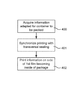
Fig. 4 is a flow chart illustrating printing operations, as of action 302 in
10 Fig. 3, according to embodiments. The printing includes acquiring 400
information configured for the container or containers to be packed at the
moment, which information then is to be printed. The information, which can be
in form of for example a barcode, a matrix barcode, text, or pictogram, or any
combination thereof, is printed on the side of the first film becoming the
inside of
the package. Therefore, it can be beneficial that the printing is performed
402
as mirrored information on the side becoming the inside of the package.
Optionally, the printing is synchronized 401 with other operations in packing,
for
example transversal sealing, such that the print becomes placed on a desired
position on the package. For example, the printing position is controlled by
the
occasion of a previous sealing operation such that the print becomes
positioned
on a desired position of the package, the printing position is controlled by
time
instant of the printing, or the printing position is controlled by a feeding
mechanism or a printer position adjusting mechanism.
Fig. 5 is a flow chart illustrating forming of the package according to
embodiments. Here, most of the actions illustrated in Fig. 5 are to be
considered as options which can be combined in any combination. For
example, the first film can be thermoformed 500 to gain a desired form of the
package. The thermoforming of the first film is preferably performed after
printing. Similarly the second film can be thermoformed 502. Upon
thermoforming 502 of the second film, the container is preferably placed 504
according to the forming on the second film, i.e. after thermoforming 502,
such
that the container becomes in the right position in the package. The first and
second films can then be joined 506 around the container. Air is optionally
evacuated 508 between the films and the container such that the films fit
tight to
the container. The films can then be welded 510 to seal the package. The
CA 02895611 2015-06-18
WO 2014/108534 PCT/EP2014/050477
11
sealing can also comprise, instead of or in addition to welding 510, any of
gluing, heat sealing, or any combination thereof.
Fig. 6 is a flow chart illustrating synchronizing for packaging the
container according to embodiments. As of Fig. 5, the actions illustrated in
Fig.
6 are to be considered as options which can be combined in any combination.
Fig. 6 is further to be considered as an alternative approach to controlling
printing position to other operations by letting the printing position control
the
succeeding operations. For this, optical approach, such as vision technology,
can be used for the control where the observed print controls the timing
and/or
position of other operations. The container placement can for example be
synchronized 600 with the position of the printed information. Transversal
sealing can also be synchronized 602 with the printed information placement.
The methods according to the present invention are suitable for
implementation with aid of processing means, such as computers and/or
processors, especially for the case where operations of a packaging machine
are controlled by digital controllers such as programmable logic controllers,
processors or computers. Therefore, there is provided computer programs,
comprising instructions arranged to cause the programmable logic controllers,
processors or computers to perform the steps of any of the methods according
to any of the embodiments described with reference to Figs 3 to 6. The
computer programs preferably comprises program code which is stored on a
computer readable medium 1100, as illustrated in Fig. 11, which can be loaded
and executed by a programmable logic controller, processor or computer 1102
to cause it to perform the methods, respectively, according to embodiments of
the present invention, preferably as any of the embodiments described with
reference to any of Figs. 3 to 6. The programmable logic controller, processor
or
computer 1102 and computer program product 1100 can be arranged to
execute the program code sequentially where actions of the any of the methods
are performed stepwise. The programmable logic controllers, processors or
computers 1102 are preferably what normally is referred to as an embedded
system. Thus, the depicted computer readable medium 1100 and
programmable logic controllers, processors or computers 1102 in Fig. 11 should
be construed to be for illustrative purposes only to provide understanding of
the
principle, and not to be construed as any direct illustration of the elements.
CA 02895611 2015-06-18
WO 2014/108534 PCT/EP2014/050477
12
Fig. 7 is a top view of a package 126 according to an embodiment. The
inner rectangle with rounded corners is here illustrating the enclosed
container
and the area outside that illustrates the parts where the two films are joined
and
sealed together. The printed information 109 is here given as example as a
matrix barcode.
Fig. 8 is a side view of the package 126. The rounded part is here
illustrating the enclosed container and the line illustrates the parts where
the
two films are joined and sealed together. The printed information 109 is here
seen to be on the package 126.
The package 126 is suitable for a container, for example a bag,
preferably a bag with liquid content. The liquid content of the bag can
comprise
a medical solution. The medical solution can for example be dialysis fluid or
water for use in medical applications. The package 126 is formed from a first
and a second film being sealed by a seal of the first and second films along a
line encircling the container. The package 126 comprises printed information
109 which is configured for the container to be packed, such as product, date,
time, batch, and/or packet identification. Thus, the printed information may
enable unique identification of the product, the batch or even the single
package. The controller controlling the printing may store information
.. accordingly in a database, wherein data corresponding to the printed
information, e.g. a metadata file, and thus the product, batch and/or package
may be retrieved, e.g. upon use of the product of the package or any found
issues regarding the product of the package. The information is printed on an
inside of the first film. Thereby is the printed information protected from
for
example wear during transportation and handling of the product. The printed
information is arranged in form of for example a barcode, a matrix barcode,
text,
pictogram, or any combination thereof.
While the invention has been described in connection with what is
presently considered to be the most practical embodiments, it is to be
.. understood that the invention is not to be limited to the disclosed
embodiments,
but on the contrary, is intended to cover various modifications and
equivalents
included within the spirit and the scope of the appended claims.