Note: Descriptions are shown in the official language in which they were submitted.
CA 02895802 2015-06-18
WO 2014/100217 PCT/US2013/076195
Method for Multi-frequency Imaging Using High-bandwidth
Transducer Outputs
Field of the Invention
The present disclosure relates generally to intravascular ultrasound (IVUS)
imaging inside the living body and, in particular, to an IVUS imaging catheter
that
produces high resolution intravascular multi-frequency imaging using high
bandwidth
transducer outputs.
Description of Related Art
Intravascular ultrasound (IVUS) imaging is widely used in interventional
cardiology as a diagnostic tool for a diseased vessel, such as an artery,
within the
human body to determine the need for treatment, to guide the intervention,
and/or to
assess its effectiveness. IVUS imaging uses ultrasound echoes to create an
image of
the vessel of interest. The ultrasound waves pass easily through most tissues
and
blood, but they are partially reflected from discontinuities arising from
tissue
structures (such as the various layers of the vessel wall), red blood cells,
and other
features of interest. The IVUS imaging system, which is connected to an IVUS
catheter by way of a patient interface module (PIM), processes the received
ultrasound echoes to produce a cross-sectional image of the vessel where the
catheter
is placed.
Current IVUS solutions do not provide the resolution capable of
differentiating structures without significant training in image
interpretation.
Structures requiring clearer images might include plaque burden, stent
apposition,
lipid pool identification, thrombus, and stent endothelization. While
Optical
Coherence Tomography (OCT) devices offer improved resolution, they require
flushing to produce the image, and due to limitations of light penetration
they do not
allow for visualization of the vessel morphology beyond the surface of the
vessel.
Furthermore, state-of-the art systems may obtain improved image resolution by
operating at higher frequencies, but at the cost of reduced tissue
penetration.
1
CA 02895802 2015-06-18
WO 2014/100217
PCT/US2013/076195
Likewise, state-of-the-art systems that operate at lower frequencies provide
deeper
tissue penetration but at a lower axial resolution.
While existing IVUS catheters deliver useful diagnostic information, there is
a
need for enhanced image quality to provide more valuable insight into the
vessel
condition. For further improvement in image quality in rotational IVUS, it is
desirable to use a transducer with broader bandwidth to incorporate multiple
frequencies in the image creation process.
What is needed is a method for multi-frequency intravascular imaging to
assess lesions, characterize vessels or to monitor other structures within a
patient's
body.
Summary
According to embodiments disclosed herein a method for imaging a volume
within a patient may include generating an ultrasonic signal at a first
selected
frequency, using a first transducer located within the tissue structure;
directing the
ultrasonic signal on a spot in the volume within the patient; scanning the
spot in a
predetermined pattern about the wall of the volume within the patient;
receiving an
ultrasonic echo in a second transducer at a second selected frequency;
converting the
ultrasonic echo into a voltage; amplifying the voltage with a processing
circuit; and
providing an image of the volume within the patient from the voltage.
In some embodiments, a method for multi-frequency imaging of a volume
within a patient may include positioning a flexible member within the volume,
proximal to a pre-selected area of interest; generating an ultrasonic signal
at a first
plurality of frequencies using a polymeric transducer located within the
volume;
directing the ultrasonic signal on a spot in the volume; scanning the spot in
a
predetermined pattern about an internal portion of the volume; receiving an
ultrasonic
echo at a second plurality of frequencies in the polymeric transducer;
converting the
ultrasonic echo into a voltage; amplifying the voltage with a processing
circuit;
2
CA 02895802 2015-06-18
WO 2014/100217
PCT/US2013/076195
providing an image of the volume from the voltage; and classifying the image
according to a characterization tool.
In some embodiments, a method for imaging a volume within a patient may
include generating an ultrasonic signal at a first plurality of frequencies,
using a
polymeric transducer located within the volume; directing the ultrasonic
signal on a
spot in the volume; scanning the spot in a predetermined pattern about a
surface in the
volume; receiving an ultrasonic echo in the polymeric transducer at a second
plurality
of frequencies; converting the ultrasonic echo into a voltage; amplifying the
voltage
with a processing circuit; and providing a plurality of images of the volume
from the
voltage.
These and other embodiments of the present invention will be described in
further detail below with reference to the following drawings.
Brief Description of the Drawings
FIG. 1A is a schematic illustration of an intravascular ultrasound (IVUS)
imaging system, according to some embodiments.
FIG. 1B is a cross-sectional side view of a distal portion of a catheter used
in
an IVUS imaging system, according to some embodiments.
FIG. 2 is a block diagram of a Patient Interface Module (PIM) for use in an
IVUS imaging system, according to some embodiments.
FIG. 3A is a partial illustration of a distal end of a catheter for multi-
frequency
imaging, according to some embodiments.
FIG. 3B is a partial illustration of a distal end of a catheter for multi-
frequency
imaging, according to some embodiments.
FIG. 4 is a partial schematic illustration of a transducer voltage, according
to
some embodiments.
3
CA 02895802 2015-06-18
WO 2014/100217
PCT/US2013/076195
FIG. 5 is a partial schematic illustration of multi-frequency voltage pulses
for
a transducer component, according to some embodiments.
FIG. 6 is a partial schematic illustration of a transmission band, a reception
band, and a response band in a multi-frequency IVUS imaging system, according
to
some embodiments.
FIG. 7 is a partial schematic illustration of a signal processing strategy for
selecting harmonic components of a signal, according to some embodiments.
FIG. 8 is a flow chart of a method for multi-frequency imaging according to
some embodiments.
FIG. 9 is a flow chart of a method for multi-frequency imaging, according to
some embodiments.
In the figures, elements having the same reference number have the same or
similar functions.
Detailed Description
For the purposes of promoting an understanding of the principles of the
present disclosure, reference will now be made to the embodiments illustrated
in the
drawings, and specific language will be used to describe the same. It is
nevertheless
understood that no limitation to the scope of the disclosure is intended. Any
alterations and further modifications to the described devices, systems, and
methods,
and any further application of the principles of the present disclosure are
fully
contemplated and included within the present disclosure as would normally
occur to
one skilled in the art to which the disclosure relates. In particular, it is
fully
contemplated that the features, components, and/or steps described with
respect to one
embodiment may be combined with the features, components, and/or steps
described
with respect to other embodiments of the present disclosure. For the sake of
brevity,
however, the numerous iterations of these combinations will not be described
separately.
4
CA 02895802 2015-06-18
WO 2014/100217
PCT/US2013/076195
In embodiments of an IVUS catheter disclosed herein, an ultrasound
transducer assembly is located at the tip of a flexible driveshaft that spins
inside a
plastic sheath inserted into the vessel of interest. The transducer assembly
includes
components oriented such that an ultrasound beam produced by the component
propagates generally perpendicular to the axis of the catheter. A fluid-filled
sheath
protects the vessel tissue from the spinning transducer and driveshaft while
permitting
ultrasound signals to freely propagate from the transducer into the tissue and
back.
As the driveshaft rotates (typically at 30 revolutions per second), the
transducer is
periodically excited with a high voltage pulse to emit a short burst of
ultrasound. The
same transducer then listens for the returning echoes reflected from various
tissue
structures, and the IVUS imaging system assembles a two dimensional display of
the
vessel cross-section from a sequence of several hundred of these
pulse/acquisition
cycles occurring during a single revolution of the transducer.
In a rotational IVUS catheter, the ultrasound transducer may be a
piezoelectric
ceramic element with low electrical impedance capable of directly driving an
electrical cable connecting the transducer to the imaging system hardware. In
this
case, a single pair of electrical leads (or coaxial cable) can be used to
carry the
transmit pulse from the system to the transducer and to carry the received
echo signals
from the transducer back to the imaging system by way of a patient interface
module
("PIM") where echo signals can be assembled into an image. In embodiments
where
the catheter driveshaft and transducer are spinning (in order to scan a cross-
section of
the artery) and the imaging system hardware is stationary, an
electromechanical
interface couples the electrical signal to a rotating junction. In rotational
IVUS
imaging systems, this may be achieved by using a rotary transformer, slip
rings, rotary
capacitors, etc.
In some embodiments, an IVUS catheter may include a plurality of transducer
components in a static configuration, forming a phased-array transducer
assembly.
Reference will now be made to a particular embodiments of the concepts
incorporated into an intravascular ultrasound system. However, the illustrated
embodiments and uses thereof are provided as examples only. Without limitation
on
5
CA 02895802 2015-06-18
WO 2014/100217
PCT/US2013/076195
other systems and uses, such as but without limitation, imaging within any
vessel,
artery, vein, lumen, passage, tissue or organ within the body. While the
following
embodiments may refer to a blood vessel and a blood vessel wall for
illustrative
purposes, any other tissue structure may be envisioned to be imaged according
to
methods disclosed herein. More generally, any volume within a patient's body
may
be imaged according to embodiments disclosed herein, the volume including
vessels,
cavities, lumens, and any other tissue structures, as one of ordinary skill
may
recognize.
FIG. 1A is a schematic illustration of an intravascular ultrasound (IVUS)
imaging system 100, according to some embodiments. IVUS imaging system 100
includes an IVUS catheter 102 coupled by a patient interface module (PIM) 104
to an
IVUS control system 106. Control system 106 is coupled to a monitor 108 that
displays an IVUS image (such as an image generated by IVUS system 100).
In some embodiments, catheter 102 is a rotational IVUS catheter, which may
be similar to a Revolution Rotational IVUS Imaging Catheter available from
Volcano Corporation and/or rotational IVUS catheters disclosed in U.S. Patent
No.
5,243,988 and U.S. Patent No. 5,546,948, both of which are incorporated herein
by
reference in their entirety, for all purposes. In some embodiments, catheter
102 may
be a stationary component.
Catheter 102 includes an elongated, flexible catheter sheath 110 (having a
proximal end portion 114 and a distal end portion 116) shaped and configured
for
insertion into a lumen of a blood vessel (not shown). In some embodiments,
IVUS
system 100 may be used for neurological evaluations in blood vessels in the
brain,
and for renal denervation in blood vessels in the kidney. A longitudinal axis
LA of
catheter 102 extends between the proximal end portion 114 and the distal end
portion
116. Catheter 102 is flexible such that it can adapt to the curvature of the
blood vessel
during use. In that regard, the curved configuration illustrated in FIG. 1A is
for
exemplary purposes and in no way limits the manner in which catheter 102 may
curve
in other embodiments. Generally, catheter 102 may be configured to take on any
desired straight or arcuate profile when in use.
6
CA 02895802 2015-06-18
WO 2014/100217
PCT/US2013/076195
In some embodiments an imaging core 112 extends within sheath 110.
Accordingly, in some embodiments imaging core 112 may be rotated while sheath
110 remains stationary. Imaging core 112 has a proximal end portion 118
disposed
within the proximal end portion 114 of sheath 110 and a distal end portion 120
disposed within the distal end portion 116 of sheath 110. The distal end
portion 116
of sheath 110 and the distal end portion 120 of imaging core 112 are inserted
into the
vessel of interest during operation of the IVUS imaging system 100. The usable
length of catheter 102 (for example, the portion that can be inserted into a
patient,
specifically the vessel of interest) can be any suitable length and can be
varied
depending upon the application. Proximal end portion 114 of sheath 110 and
proximal end portion 118 of imaging core 112 are connected to PIM 104.
Proximal
end portions 114, 118 are fitted with a catheter hub 124 that is removably
connected
to PIM 104. Catheter hub 124 facilitates and supports a rotational interface
that
provides electrical and mechanical coupling between catheter 102 and PIM 104.
Distal end portion 120 of imaging core 112 includes a transducer assembly
122. In some embodiments, transducer assembly 122 is configured to be rotated
(either by use of a motor or other rotary device, or manually by hand) to
obtain
images of the vessel. Transducer assembly 122 can be of any suitable type for
visualizing a vessel and, in particular, a stenosis in a vessel. In the
depicted
embodiment, transducer assembly 122 includes a piezoelectric micro-machined
ultrasonic transducer ("PMUT") and associated circuitry, such as an
application-
specific integrated circuit (ASIC). An exemplary PMUT used in IVUS catheters
may
include a polymer piezoelectric membrane, such as that disclosed in U.S.
Patent No.
6,641,540, and co-pending applications entitled "Preparation and Application
of a
Piezoelectric Film for an Ultrasound Transducer," Attorney Docket No.
44755.1062,
"Focused Rotational IVUS Transducer Using Single Crystal Composite Material,"
Attorney Docket No. 44755.931, and "Transducer Mounting Arrangements and
Associated Methods for Rotational Intravascular Ultrasound (IVUS) Devices,"
Attorney Docket No. 44755.960, each hereby incorporated by reference in its
entirety.
The PMUT may provide greater than 100% bandwidth for optimum resolution in a
radial direction, and a spherically-focused aperture for optimum azimuthal and
7
CA 02895802 2015-06-18
WO 2014/100217
PCT/US2013/076195
elevation resolution. Thus, transducer assembly 122 may provide a focused
ultrasonic
beam having a spot size of about 50 p m or less.
In some embodiments transducer assembly 122 may include a plurality of
stationary components disposed around the circumference of distal end 120 of
catheter 102. In such configuration, the components in transducer 122 may be
piezo-
electric elements distributed to form a phased-array configuration. The piezo-
electric
elements may be ceramic-based or polymer-based. Furthermore, in some
embodiments the plurality of stationary components in transducer 122 may be
configured to produce a focused acoustic impulse. In such embodiments, the
stationary components produce an acoustic impulse according to a pre-selected
excitation phase for each of the components.
Transducer assembly 122 may also include a housing having the PMUT and
associated circuitry disposed therein. In some embodiments the housing has an
opening that ultrasound signals generated by the PMUT transducer travel
through.
Alternatively, transducer assembly 122 includes a capacitive micro-machined
ultrasonic transducer ("CMUT"). In yet another alternative embodiment, the
transducer assembly 122 includes an ultrasound transducer array (for example,
arrays
having 16, 32, 64, or 128 components are utilized in some embodiments).
In some embodiments, a rotation of imaging core 112 within sheath 110 is
controlled by PIM 104. For example, PIM 104 provides user interface controls
that
can be manipulated by a user. In some embodiments PIM 104 may receive,
analyze,
and/or display information received through imaging core 112. It will be
appreciated
that any suitable functionality, controls, information processing and
analysis, and
display can be incorporated into PIM 104. Thus, PIM 104 may include a
processor
circuit 154 and a memory circuit 155 to execute operations on catheter 102 and
receive, process, and store data from catheter 102. In some embodiments PIM
104
receives data associated to ultrasound signals (echoes) detected by imaging
core 112.
PIM 104 processes the data and forwards the processed echo data to control
system
106. Control system 106 may include a processor circuit 156 and a memory
circuit
157 to execute operations on catheter 102 and receive, process, and store data
from
catheter 102. In some embodiments, PIM 104 performs preliminary processing of
the
8
CA 02895802 2015-06-18
WO 2014/100217
PCT/US2013/076195
echo data prior to transmitting the echo data to control system 106. PIM 104
may
perform amplification, filtering, and/or aggregating of the echo data, using
processor
circuit 154 and memory circuit 155. PIM 104 can also supply high- and low-
voltage
DC power to support operation of catheter 102 including circuitry within
transducer
assembly 122.
In some embodiments, wires associated with IVUS imaging system 100
extend from control system 106 to PIM 104. Thus, signals from control system
106
can be communicated to PIM 104 and/or vice versa. In some embodiments, control
system 106 communicates wirelessly with PIM 104. Similarly, it is understood
that,
in some embodiments, wires associated with IVUS imaging system 100 extend from
control system 106 to monitor 108 such that signals from control system 106
can be
communicated to monitor 108 and/or vice versa. In some embodiments, control
system 106 communicates wirelessly with monitor 108.
Piezoelectric micro-machined ultrasound transducers (PMUTs) fabricated
using a polymer piezoelectric material for use in transducer assembly 122,
such as
disclosed in U.S. Patent 6,641,540 that is hereby incorporated by reference in
its
entirety, offer greater than 100% bandwidth for optimum resolution in the
radial
direction, and a spherically-focused aperture for optimum azimuthal and
elevation
resolution.
FIG. 1A illustrates a 3-dimensional (3D) Cartesian coordinate system XYZ
oriented such that the Z-axis is aligned with the LA. In further descriptions
of
embodiments disclosed herein, a reference to a Cartesian plane or coordinate
may be
made in relation to FIG. 1. One of ordinary skill will recognize that the
particular
choice of coordinate axes in FIG. 1A is not limiting of embodiments as
disclosed
herein. The choice of coordinate axes is done for illustration purposes only.
FIG. 1B is a cross-sectional side view of a distal portion of a catheter used
in
an IVUS imaging system, according to some embodiments. In particular, Fig. 1B
shows an expanded view of aspects of the distal portion of imaging core 112.
In this
exemplary embodiment, imaging core 112 is terminated at its distal tip by a
housing
126 having a rounded nose and a cutout 128 for the ultrasound beam 150 to
emerge
9
CA 02895802 2015-06-18
WO 2014/100217
PCT/US2013/076195
from the housing. In some embodiments, a flexible driveshaft 132 of imaging
core
112 is composed of two or more layers of counter wound stainless steel wires,
welded, or otherwise secured to housing 126 such that rotation of the flexible
driveshaft also imparts rotation to housing 126. In the illustrated
embodiment, a
PMUT MEMS transducer layer 121 includes a spherically focused portion facing
cutout 128. In some embodiments, transducer assembly 122 may include
application-
specific integrated circuit (ASIC) 144 within distal portion 120 of imaging
core 112.
ASIC 144 is electrically coupled to transducer layer 221 through two or more
connections.
In some embodiments of the present disclosure ASIC 144 may include an
amplifier, a transmitter, and a protection circuit associated with PMUT MEMS
layer
121. In some embodiments, ASIC 144 is flip-chip mounted to a substrate of the
PMUT MEMS layer 121 using anisotropic conductive adhesive or suitable
alternative
chip-to-chip bonding method. When assembled together PMUT MEMS layer 121
and ASIC 144 form an ASIC/MEMS hybrid transducer assembly 122 mounted within
housing 126. An electrical cable 134 with optional shield 136 may be attached
to
transducer assembly 122 with solder 140. Electrical cable 134 may extend
through an
inner lumen of the flexible driveshaft 132 to proximal end 118 of imaging core
112.
In proximal end 118, cable 134 is terminated to an electrical connector
portion of a
rotational interface coupling catheter 102 to PIM 104 (cf. FIG. 1A). In the
illustrated
embodiment, transducer assembly 122 is secured in place relative to the
housing 126
by an epoxy 148 or other bonding agent. Epoxy 148 may serve as an acoustic
backing material to absorb acoustic reverberations propagating within housing
126
and as a strain relief for the electrical cable 134 where it is soldered to
transducer
assembly 122.
FIG. 2 is a block diagram of a Patient Interface Module (PIM) 104 for use in
an IVUS imaging system, according to some embodiments. PIM 104 includes
processor circuit 154 and memory circuit 155, described in detail above in
relation to
FIG. 1. PIM 104 provides a control signal 223 to a catheter, and receives data
224
from the catheter (e.g., catheter 102, FIG. 1). Control signal 223 may include
a
sequence of voltage pulses creating an acoustic impulse from a transducer
assembly
(e.g., transducer assembly 122). In some embodiments, control signal 223 is
CA 02895802 2015-06-18
WO 2014/100217
PCT/US2013/076195
generated in a pulse transmitter 212 included in processor circuit 154. In
some
embodiments, each pulse from a plurality of pulses may include a single cycle
of a
signal having a selected frequency. In such embodiments, the frequency
spectrum of
such a pulse will be a signal centered at the selected frequency, having a
bandwidth.
Accordingly, pulse transmitter 212 may be configured to generate a plurality
of
voltage pulses centered at a plurality of frequencies. For example, the
plurality of
center frequencies for pulses provided by pulse transmitter 212 may include
different
frequencies, such as baseband frequencies and their harmonics. Thus, according
to
some embodiments, pulse transmitter circuit 212 has a transmission band which
may
include multiple center frequencies for a plurality of pulses provided to a
transducer
assembly.
In some embodiments, data 224 includes electrical signals received from
catheter 102 and amplified by receive amplifier 214. The electrical signals in
data
224 may be voltage signals. According to some embodiments, data 224 is an
analog
signal associated to an ultrasonic echo from a tissue structure around the
transducer
assembly. Analog-to-digital converter (ADC) 216 converts amplified electrical
signal
224 into a digital signal. In some embodiments, the digital signal from ADC
216 is
further processed by a reconstruction circuit 250. In some embodiments, data
224
includes voltage signals produced by the transducer assembly upon receiving an
ultrasound echo signal from a tissue structure. The tissue structure may be
surrounding a distal end of a catheter that includes the transducer assembly
(e.g.,
distal end 120, cf. FIG. 1). The voltage signal in data 224 may include tissue
responses at a plurality of frequencies, forming a reception band. Thus,
receive
amplifier 214 may include filters that produce a bandwidth including the
reception
band. Accordingly, in some embodiments the filtering of incoming data 224 and
outgoing control signal 223 may be performed by ASIC 144 at distal end portion
120
of catheter 102 (cf. FIG. 1B).
Reconstruction circuit 250 may perform operations on the digitized, amplified
data 224 such as data smoothing, averaging, noise filtering, and data
interpolation.
Thus, in some embodiments reconstruction circuit 250 may prepare the data
provided
by transducer assembly 122 for an image rendition of the tissue surrounding
distal end
11
CA 02895802 2015-06-18
WO 2014/100217
PCT/US2013/076195
120 of catheter 102. The reconstructed digital data is transferred out of PIM
104 to
IVUS control system 106 by a communication protocol circuit 218.
In some embodiments, a clock and timing circuit 200 provides a digitizing
signal 226 to ADC 216, and transmitter timing signal 222 to pulse transmitter
212.
According to some embodiments, clock and timing circuit 200 provides
transmitter
timing signal 222 and digitizing signal 226 using a common stable system
clock.
Some embodiments may include a phase-locked loop circuit in clock and timing
circuit 200 to synchronize transmitter timing signal 222 and digitizing signal
226. In
some embodiments transmitter timing signal 222 and digitizing signal 226 have
the
same phase, or their relative phase is fixed in time to within the resolution
of clock
and timing circuit 200.
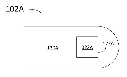
FIG. 3A is a partial illustration of a distal end 120A of a catheter 102A for
multi-frequency imaging, according to some embodiments. Distal end 120A
includes
transducer assembly 122A. Accordingly, transducer assembly 122A includes a
single
piezo-electric component 322A. In embodiments consistent with the present
disclosure, piezo-electric component 322A may have a response band that
includes
the transmission band of a pulse transmitter 212 and the reception band of
receive
amplifier 214. The response band of piezo-electric component 322A is
determined by
the material forming the component, and the geometry of the component.
According
to some embodiments, the response band of a transducer element is measured by
the
voltage amplitude produced when an acoustic wave of a certain frequency
impinges
on the transducer. In some embodiments, it is desirable to have a broad
response
bandwidth for piezo-electric component 322A. For example, in some embodiments
a
response band from about 5 MHz to about 135 MHz may be achievable using
polymer-based transducer assemblies. In some embodiments, the polymer used in
transducer assembly 322A may be a ferroelectric polymer such as polyvinylidene
fluoride (PVDF). Further according to some embodiments, a polymer used in
transducer assembly 322A may include PVDF-co-trifluoroethylene (PVDF-TrFE) as
a
piezo-electric material. Alternatively, polymers such as PVDF-CTFE or PVDF-CFE
may be used.
12
CA 02895802 2015-06-18
WO 2014/100217
PCT/US2013/076195
Thus, according to embodiments consistent with the present disclosure a pulse
transmitter circuit 212 provides a plurality of pulses within a transmission
band to a
single piezo-electric component 322A. Likewise, a single piezo-electric
component
322A may receive an ultrasound echo within a reception band from a tissue
structure.
The tissue structure may be a blood vessel wall surrounding distal end 120A of
catheter 102.
FIG. 3B is a partial illustration of a distal end 120B of a catheter 102B for
multi-frequency imaging, according to some embodiments. Distal end 120B
includes
transducer assembly 122B. Transducer assembly 122B may include a plurality of
piezo-electric components 322B-1, 322B-2, 322B-3, 322B-4, 322B-5, and 322B-6
(collectively referred to hereinafter as `piezo-electric components 322B').
One of
ordinary skill will recognize that the specific number of piezo-electric
components
322B in assembly 122B is arbitrary and not limiting. Furthermore, the specific
shape
and arrangement of components 322B is also not limiting, depending only in the
specific application of a multi-frequency imaging catheter 102.
In some embodiments, a first selected group of components 322B may be used
for transmitting ultrasound pulses, and a second selected group of components
322B
may be used for receiving ultrasound echoes. The first selected group of
components
322B may be different from the second selected group of components 322B.
Therefore, in some embodiments each of the components 322B-1 through 322B-6
may have a narrow response band, tuned to the specific function of the
component
(e.g., transmission, reception, or both). For example, component 322B-1 may
have a
response band including a portion of the transmission band. Likewise,
component
322B-2 may have a response band including a portion of the reception band.
Accordingly, a first selected group of ultrasound pulses provided to the first
selected
group of components 322B may be centered at a first selected group of
frequencies.
The first selected group of frequencies may include ultrasound frequencies
such as 20
MHz, 40 MHz, and 80 MHz. Likewise, a receive amplifier in a processor circuit
for a
PIM module coupled to transducer 122B may have filters with bandwidths
selected
according to the response band of the second selected group of components
322B.
Thus, radio-frequency (RF) filters in a response amplifier inside a PIM may be
centered at a second selected group of frequencies such as 20 MHz, 40 MHz, and
80
13
CA 02895802 2015-06-18
WO 2014/100217
PCT/US2013/076195
MHz. In some embodiments, RF filters may be included in ASIC 144 at distal end
portion 120 of catheter 102, to filter the echo signal in a selected response
band.
Accordingly, the second selected group of frequencies may include harmonic
combinations of the first selected group of frequencies. A harmonic
combination may
include integer multiples of a frequency in the first selected group of
frequencies. In
some embodiments, a harmonic combination may include a sum of frequencies from
the first selected group of frequencies. For example, when a first selected
group of
frequencies includes 20 MHz, 40 MHz, and 80 MHz, a second selected group of
frequencies may include 40 MHz (= 2 x 20 MHz), 80 MHz (= 2 x 40 MHz), 60 MHz
(= 20 MHz + 40 MHz), and even 120 MHz (= 40 MHz + 80 MHz).
Thus, according to some embodiments, transducer assembly 122B may
provide a wide response band by using multiple transducer components 322B.
Each
of transducer components 322B may have a narrow response band covering a
portion
of a transmission band or a portion of a reception band, centered at a
selected
frequency. Such a configuration may be desirable since piezo-electric
components
with a narrow response band may provide high response efficiency.
FIG. 4 is a partial schematic illustration of a transducer voltage 400,
according
to some embodiments. Transducer voltage 400 includes voltage values across a
transducer component in a transducer assembly, as a function of time (e.g.,
transducer
assemblies 122A, 122B in FIGS. 3A, 3B above). Transducer voltage 400 includes
ultrasound pulse transmit portions 411-1, 411-2, and 411-3, collectively
referred to
hereinafter as 'transmission portions 411.' Likewise, transducer voltage 400
includes
ultrasound echo reception portions 421-1, 421-2, and 421-3, collectively
referred to
hereinafter as 'reception portions 421.' While FIG. 4 illustrates three
transmission
portions 411 and three reception portions 421, one of ordinary skill will
recognize that
there is nothing limiting in the number of transmission portions 411, and
reception
portions 421 that may be used. Moreover, in some embodiments the number of
transmission portions 411 may be different from the number of reception
portions
421. FIG. 4 illustrates each one of transmission portions 411 followed by a
reception
portion 421. It will be recognized by those with ordinary skill that one or
more
transmission portions 411 may be provided in sequence, before a reception
portion
14
CA 02895802 2015-06-18
WO 2014/100217
PCT/US2013/076195
421 follows. Likewise, a plurality of reception portions 421 may be provided
in
sequence, after a transmission portion 411.
Transmission portions 411 include pulses 401-1, 401-2, and 401-3 provided by
a pulse transmitter circuit (e.g., pulse transmitter 212, cf. FIG. 2) to the
transducer
assembly. Pulses 401-1 through 401-3 are collectively referred to hereinafter
as
pulses 401. Reception portions 421 include signals 402-1, 402-2, and 402-3
provided
by the transducer assembly to an amplifier circuit (e.g., receive amplifier
214, cf. FIG.
2). Signals 402-1, 402-2, and 402-3 are referred to hereinafter as ultrasound
echo
signals 402. Accordingly, ultrasound echo signals 402 may be tissue responses
to
pulses 401. Moreover, depending on the frequency component of pulses 401,
ultrasound echo signals 402 may proceed from different portions of a tissue
structure
surrounding the transducer assembly. Thus, ultrasound echo signal 402-3
corresponding to a pulse 401-3 having a high center frequency may proceed from
a
shallow region of the tissue structure. For example, a signal 402
corresponding to a
pulse 401 centered at about 80 MHz may proceed from an area of a blood vessel
wall
proximate to the lumen of the vessel.
FIG. 5 is a partial schematic illustration of multi-frequency voltage pulses
for
a transducer component, according to some embodiments. FIG. 5 illustrates
voltage
pulses 501-1, 501-2, and 501-3, collectively referred hereinafter as voltage
pulses
501. Consistent with FIG. 5, each of pulses 501 includes a cycle having a
period 551-
1, 551-2, and 551-3, collectively referred hereinafter as period values 551.
Accordingly, period 551-1 may be different from period 551-2, thus
corresponding to
a pulse 501-1 centered at a lower frequency than the center frequency of pulse
501-2.
For example, if period 551-1 is double the length of period 551-2, the center
frequency of pulse 501-2 will be at double the frequency of the center of
pulse 501-1.
Likewise, period 551-3 may be even shorter than period 551-1, corresponding to
an
even higher center frequency for pulse 501-3. One of ordinary skill will
recognize
that pulses 501 may include any one of a plurality of period values 551.
In embodiments consistent with the present disclosure it is desirable that the
transducer assembly receiving pulses 501 has a response bandwidth including
the
center frequencies of each of pulses 501. In some embodiments using a
plurality of
CA 02895802 2015-06-18
WO 2014/100217
PCT/US2013/076195
transducer components (e.g., components 322B, FIG. 3B), each of pulses 501 may
be
directed to a different transducer component optimized to operate at a
specific center
frequency. For example, transducer component 322B-1 may be designed to operate
with maximum efficiency at the center frequency corresponding to period 551-1.
One
of ordinary skill will recognize that there is no limitation as to the number
of different
periods 551 that may be provided. Also, the specific center frequency
associated to a
given period 551 may be chosen according to a specific application or need.
For
example, a period 551 may correspond to a frequency of 20 MHz, 40 MHz, 80 MHz,
or more. In some embodiments, one of periods 551 may include a frequency of 10
MHz, or less.
In addition to obtaining information from different portions of a tissue
structure using multi-frequency pulses as in FIG. 5, images having different
axial
resolution may be obtained. For example, an image generated with ultrasound
echo
signal from pulse 501-1 may have longer penetration depth within the tissue,
and
lower axial resolution, compared to an image generated from pulse 501-2. An
image
obtained from pulse 501-3 may provide higher axial resolution at a lower
penetration
depth.
FIG. 6 is a partial schematic illustration of a transmission band 611, a
reception band 621, and a response band 651 in a multi-frequency IVUS imaging
system, according to some embodiments. In FIG. 6, response band 651 is a broad
band including transmission band 611 and reception band 621. Transmission band
611 includes a transmission curve 601 centered at a first frequency 1.1, and
reception
band 621 includes a reception curve 602 centered at a second frequency, f2.
According to some embodiments, the second frequency may be a second harmonic
of
the first frequency (f2 = 2xfi). An embodiment such as illustrated in FIG. 6
may
correspond to the spectral configuration of a multi-frequency IVUS imaging
system
using a single transducer (e.g., transducer 122A, cf. FIG. 3A). In some
embodiments
reception band 621 may lay outside of response band 651 of the transducer
providing
transmission band 611. Such embodiments may correspond to a multi-frequency
IVUS imaging system using a plurality of transducer components (e.g.,
transducer
122B, FIG. 3B). For example, transmission band 611 and response band 661 may
16
CA 02895802 2015-06-18
WO 2014/100217
PCT/US2013/076195
correspond to transducer component 322B-1. Further, reception band 621 from
component 322B-2 may be outside of response band 661.
A multi-frequency IVUS imaging system as disclosed herein may include a
PIM coupled to a catheter having a transducer assembly with a transmission
band, a
reception band, and a response band as illustrated in FIG. 6 (e.g., system
100, PIM
104, catheter 102, and transducer assembly 122, FIG. 1). The PIM may include a
processor circuit to provide a pulse signal to the transducer assembly and
receive an
ultrasound echo from the signal (e.g., processor circuit 154). The processor
circuit
may include a pulse transmitter circuit having a bandwidth such as
transmission band
611 (e.g., pulse transmitter 212). The processor circuit may also include a
receive
amplifier having a bandwidth as reception band 621 (e.g., receive amplifier
214). The
bandwidth of the pulse transmission circuit and the receive amplifier circuit
may be
adjusted using RF circuit filtering techniques. In some embodiments RF circuit
filters
may be included in ASIC 144, at distal end portion 120 of catheter 102.
FIG. 7 is a partial schematic illustration of a signal processing strategy for
selecting harmonic components 750 of a signal 705, according to some
embodiments.
In some embodiments, an ADC circuit includes a frequency mixer 710 (e.g., ADC
216, FIG. 2). Mixer 710 combines signal 705 from an amplifier circuit with a
local
oscillator signal at a harmonic frequency 720. In some embodiments, the
harmonic
frequency of the local oscillator is an integer multiple of a center frequency
included
in a pulse signal for a transducer assembly (e.g., any one of pulses 501, cf.
FIG. 5).
For example, if a center frequency in a pulse signal is 'f', the harmonic
frequency 720
of the local oscillator in mixer 710 may be '2 x f'. Frequency mixer 710 may
include
a feedback circuit using a phase-lock signal provided by a timing circuit
(e.g., clock
and timing circuit 200, FIG. 2). For example, in some embodiments the phase
lock
signal may be included in digitizing signal 226 (cf. FIG. 2). Harmonic
component
750 of signal 705 may thus be transmitted to a reconstruction circuit for
imaging (e.g.,
reconstruction circuit 250).
FIG. 8 is a flow chart illustrating steps in a method 800 for multi-frequency
imaging, according to some embodiments. According to some embodiments, method
800 may be performed by a control system (e.g., control system 106) using a
17
CA 02895802 2015-06-18
WO 2014/100217
PCT/US2013/076195
processor circuit (e.g., processor circuit 156) and a memory circuit (e.g.,
memory
circuit 157) and/or a PIM (e.g., PIM 104) using a processor circuit (e.g.
processor
circuit 154) and a memory circuit (e.g., memory circuit 155) based on scan
data
provided by a transducer assembly (e.g., transducer assembly 122 cf. FIG. 1).
The
transducer assembly may be in the distal end of a catheter positioned inside
the lumen
of a tissue structure (cf. catheter 102, FIG. 1). In some embodiments, steps
in method
800 may be performed by the control system and steps in method 800 may be
performed by the PIM. A reconstructed image plane in method 800 may be
provided
to a user in a display (e.g., display 108). In some embodiments, the
reconstructed
image is a 3-dimensional image (3D-image) including a plurality of cross-
sectional
planes of a tissue structure.
Step 810 includes generating an ultrasonic signal at a first selected
frequency.
In some embodiments, the ultrasonic signal may be generated from a transducer
assembly (e.g., transducer assembly 122, cf. FIG. 1) in the form of an
ultrasound
acoustic beam following a path. The ultrasound acoustic beam path may be
focused,
to produce a focal region of high intensity acoustic energy in a target
portion of a
tissue. Step 810 may include providing a voltage pulse to a transducer
assembly
122A, B (cf. FIGS. 3A, B). Accordingly, a voltage pulse may be provided by the
PIM
to transducer assemblies 122A, B for a pre-selected period of time.
Furthermore, a
voltage pulse for transducer assemblies 122A, B may be provided in a series of
pulses
such as pulses 401, or pulses 501 produced at a preselected center frequency
(cf.
FIGS. 4 and 5). In some embodiments of method 800, step 810 may include
generating a plurality of pulses at a first plurality of center frequencies.
The first
plurality of center frequencies may include different center frequencies.
Step 820 includes scanning the ultrasonic signal in a predetermined pattern
about the interior wall of a structure. In some embodiments, step 820 may
include
sweeping the ultrasonic signal continuously in a helicoid pattern about an
interior wall
of a blood vessel. According to some embodiments, step 820 is accomplished by
rotating the transducer or rotating a reflective surface which deflects the
signal from
the transducer within a catheter. The catheter may remain substantially
stationary
while the transducer is rotated and the acoustic signal is swept radially
around the LA
of the catheter. Further according to some embodiments, step 820 includes a
18
CA 02895802 2015-06-18
WO 2014/100217
PCT/US2013/076195
stationary transducer assembly having multiple components around a
circumference
(e.g., transducers 322B, cf. FIG. 3B). Thus, by sequentially altering the
phase
relationship between each of the components in the circumference, an
ultrasonic beam
may be scanned radially around the LA of the catheter.
Step 830 includes receiving an ultrasonic echo from the interior wall of the
structure at a second selected frequency. According to some embodiments, step
830
may be performed using the transducer assembly of step 810. Thus, upon
receiving
the ultrasonic echo from the interior wall of the structure, a deformation
induced in a
piezo-electric material in the transducer assembly may result in a voltage
signal. The
transducer assembly may be configured to couple the voltage signal out of a
surrounding tissue structure into a processor circuit (e.g., processor circuit
154 in PIM
104).
In some embodiments, step 830 may be performed during a period of time
between two voltage pulses 401 generating acoustic signals according to step
810 (cf.
FIG. 4). Thus, according to some embodiments in step 810 a voltage signal
travels
from the processor circuit in the PIM to the transducer assembly along a
catheter (e.g.,
catheter 102, FIG. 1) at a first selected frequency. Further according to some
embodiments, in step 830 a voltage signal travels from the transducer assembly
to the
processor circuit in the PIM. The voltage signal may include the second
selected
frequency. In some embodiments, the second selected frequency may be centered
at a
harmonic frequency of the first frequency. Furthermore, in some embodiments
the
second selected frequency includes the first plurality of selected frequencies
of step
810. In some embodiments, the second selected frequency may include a sum of
two
different frequencies from the first plurality of selected frequencies in step
810.
Further according to some embodiments, the second selected frequency may
include
an integer multiple of either one of the frequencies from the first plurality
of selected
frequencies.
Step 840 includes amplifying the ultrasonic echo in the processor circuit. In
some embodiments, step 840 may include filtering the ultrasonic echo signal
using
electronic filters having a band-pass including the second selected frequency.
Accordingly, a portion of step 840 may be performed by an ASIC circuit at a
distal
19
CA 02895802 2015-06-18
WO 2014/100217
PCT/US2013/076195
end of the catheter (e.g., ASIC 144 in FIG. 1B). Step 850 includes producing
an
image from the ultrasonic echo. According to some embodiments, step 850 may be
performed partially by the PIM. For example, step 850 may be partially
performed by
a reconstruction circuit (e.g., reconstruction circuit 250, FIG. 2). In
some
embodiments, step 850 may be performed partially by the control system.
According
to some embodiments, step 850 includes producing a 2-dimensional image (2D-
image) of a cross section of the blood vessel wall. The cross-section may be
substantially parallel to an XY-plane perpendicular to a LA oriented along the
blood
vessel and the catheter direction (cf. FIG. 1). In some embodiments, step 850
includes producing a 3-dimensional image (3D-image) of the blood vessel wall
from a
plurality of 2D-images.
Step 860 includes classifying the image from the amplified ultrasonic echo.
Step 860 may be performed by the processor circuit and the memory circuit in
the
control system. In some embodiments, step 860 is performed by processor
circuit 156
executing commands, retrieving and storing data, the commands and the data
being
stored in memory circuit 157. For example, in some embodiments the commands
executed by processor circuit 156 in control system 106 may be included in an
image
characterization code stored in memory circuit 157.
The image characterization code may render a characterized tissue component
map. In some embodiments, the image characterization application performs a
spectral analysis of ultrasound echo information for a vessel cross-section.
Thus,
different plaque components may be determined and distinguished in the
characterized tissue component map. For example, the characterization
application
may use a classification criterion including a rule based upon a location of a
confluence of necrotic core within the vessel cross-section in relation to a
border
between the lumen and a plaque. A classification criterion may include a rule,
based
upon a location, in relation to a lumen-plaque border, of confluent necrotic
core
within the vessel cross-section; and rendering, in response to the
classification, a
plaque classification associated with the vessel cross-section. For example, a
classification criterion may use the thickness of fibrous cap to determine the
vulnerability of a plaque, and the likelihood of plaque rupture and
thrombosis. Image
characterization applications as used in step 860 may be as disclosed in US
PAT. No.
CA 02895802 2015-06-18
WO 2014/100217
PCT/US2013/076195
7,627,156 entitled "Automated lesion analysis based upon automatic plaque
characterization according to a classification criterion," US PAT. No.
7,175,597
entitled "Non-Invasive Tissue Characterization System and Method," and US PAT.
No. 6,200,268 entitled "Vascular Plaque Characterization," each incorporated
herein
by reference in its entirety, for all purposes.
FIG. 9 is a flow chart illustrating steps in a method 900 for multi-frequency
imaging, according to some embodiments. Method 900 may be performed partially
by system 100. According to some embodiments, method 900 may be performed by a
control system (e.g., control system 106) using a processor circuit (e.g.,
processor
circuit 156) and a memory circuit (e.g., memory circuit 157) and/or a PIM
(e.g., PIM
104) using a processor circuit (e.g. processor circuit 154) and a memory
circuit (e.g.,
memory circuit 155) based on scan data provided by a transducer assembly
(e.g.,
transducer assembly 122 cf. FIG. 1). The transducer assembly may be positioned
in
the distal end of a catheter positioned inside the lumen of a tissue structure
(cf.
catheter 102, FIG. 1). In some embodiments, steps in method 900 may be
performed
by the control system and steps in method 900 may be performed by the PIM.
A reconstructed image plane in method 900 may be provided to an external
operator in display 108. Thus, the external operator makes a decision of
whether to
excise a portion of the stenosed segment of the blood vessel using a
recanalization
tool, based on the reconstructed image plane on display 108. According to some
embodiments the recanalization tool may be a physical instrument having a
sharp end.
In some embodiments, the recanalization tool may be a laser beam susceptible
of
being directed to a point in the blood vessel and ablate a tissue portion.
Further
according to some embodiments the recanalization tool may include an abrasive
surface that may be rubbed against the target tissue.
Step 910 includes generating an ultrasonic signal at a first plurality of
frequencies. Step 910 may further include positioning catheter 102 with its LA
substantially aligned with the blood vessel, inside the lumen portion of the
blood
vessel. Step 920 includes scanning the ultrasonic signal in a predetermined
pattern
about the interior wall of a structure. In some embodiments the interior wall
of a
structure is the interior portion of a blood vessel wall including a region of
stenosis.
21
CA 02895802 2015-06-18
WO 2014/100217
PCT/US2013/076195
The region of stenosis may include a plaque having a calcified portion, a
lipid pool,
and a necrotic core adjacent to the lipid pool.
Step 930 includes receiving an ultrasonic echo from the interior wall of the
structure, within a reception band of frequencies. In some embodiments, a
reception
band of frequencies in step 930 may include the first plurality of
frequencies. In some
embodiments, the reception band of frequencies may include harmonic
combinations
of the first plurality of frequencies. Harmonic combinations of the first
plurality of
frequencies may include integer multiples of either of the frequencies in the
first
plurality of frequencies. Furthermore, harmonic combinations of the first
plurality of
frequencies may include sums of any number of frequencies in the first
plurality of
frequencies. Step 940 includes amplifying the ultrasonic echo in a processor
circuit.
Step 940 may be as step 840 described in detail above, in relation to method
800.
Step 950 includes producing a plurality of images from the amplified
ultrasonic echo.
Accordingly, step 950 may include producing an image for each of the
frequencies
within the reception band of frequencies in step 930. Producing each image in
step
950 may be as described in detail above, with relation to step 850, in method
800.
Step 960 includes combining the plurality of images from step 950 to form an
image. In some embodiments, step 950 may include combining a portion of a
first
image obtained with a high frequency ultrasound echo with a portion of a
second
image obtained with a low frequency ultrasound echo. Accordingly, the portion
of
the first image may be a shallower portion of the tissue structure, and the
portion of
the second image may be a deeper portion of the tissue structure. Furthermore,
the
portion of the second image may filter out blood speckle artifacts typically
encountered in high frequency ultrasound signal, such as used for the first
image. For
example, a first portion of an image of a blood vessel obtained at 80 MHz may
include the endothelium of the blood vessel, including the border between the
blood
vessel wall and the lumen. A second portion of an image of a blood vessel
obtained at
20 MHz may include portions of necrotic tissue in a plaque, macrophage cells,
and
muscle cells deeper into the blood vessel wall.
Step 970 includes classifying the image obtained in step 960. Step 970 may
be performed by processor circuit 156 and memory circuit 157 in control system
106.
22
CA 02895802 2015-06-18
WO 2014/100217
PCT/US2013/076195
In some embodiments, step 970 is performed by processor circuit 156 executing
commands, retrieving and storing data, the commands and the data being stored
in
memory circuit 157. For example, in some embodiments the commands executed by
processor circuit 156 in control system 106 may be included in an image
characterization code stored in memory circuit 157. The image characterization
code
may render a characterized tissue component map. In some embodiments, the
image
characterization application is able to perform a spectral analysis of
ultrasound echo
information for a blood vessel cross-section. Thus, different plaque
components may
be determined and distinguished in the characterized tissue map. For example,
the
characterization application may use a classification criterion including a
rule based
upon a location of a confluence of necrotic core within the vessel cross-
section in
relation to a border between the lumen and a plaque.
In some embodiments, a classification criterion may use the thickness of a
fibrous cap to determine the vulnerability of a plaque, and the likelihood of
plaque
rupture and thrombosis. For example, a plaque may be classified as
'vulnerable' to
rupture, based on the size, configuration, and nature of its components. A
component
of a plaque within a blood vessel may be a fibrous cap and a necrotic core. In
some
configurations a component of a plaque within a vessel may include fat cell
tissue and
macrophage cells. The nature of a component of a plaque within a vessel may
include
substances such as elastin, collagen and cholesterol. The viscoelastic
properties of the
substances and the configuration of the different components included in a
plaque
within a vessel provide a differentiated acoustic response to the ultrasonic
signals in
step 910. Thus, interaction of the blood vessel wall with ultrasonic signals
in step 910
may produce an image that clearly differentiates the components of the plaque,
their
nature, and their configuration (size and shape).
Embodiments of the invention described above are exemplary only. One
skilled in the art may recognize various alternative embodiments from those
specifically disclosed. Those alternative embodiments are also intended to be
within
the scope of this disclosure. As such, the invention is limited only by the
following
claims.
23