Note: Descriptions are shown in the official language in which they were submitted.
CA 02896148 2015-06-22
WO 2014/102040 PCT/EP2013/075347
1
TURNING SYSTEM FOR BELT TRANSPORT SYSTEM
Description
Field of the invention
The present invention pertains to the technical field of platforms and
passageways for the transportation of people and goods, specifically to belts
formed by
pallets and more specifically to turning systems that employ said pallet belts
in order to
change the travelling direction. The object of the present invention is a
turning system
for these belt transport systems, in which said turning is carried out
horizontally by
means of a curved stretch arranged on the same horizontal plane as that formed
by the
turn input stretch and the turn output stretch.
Background of the invention
In passageways or platforms used to transport people and goods and
specifically
those which consist of belts formed by pallets, it is necessary to turn these
pallets in
order to successfully change the travelling direction of the belt. For
example,
passageways used to transport people in a linear fashion travel in both
possible
directions. In this case, when the end of the track is reached in one
direction, the pallets
of the belt should turn around in order to continue moving forwards in the
other
direction.
Up until present, this turn was carried out vertically, in such a way that the
two
forwards directions of the belt made of pallets were made at two different
heights. In
other words, a forwards outward movement is produced in one direction and at
the end
of the forwards course, the vertical turn is produced and the return is
produced at a
lower level.
Documents US3939959 and US4276976 show passageways or platforms for
transporting people or goods, in which the platform moves forwards in one
direction
and at the end of the forwards moving trajectory, the vertical turn is
produced and the
platform returns in the opposite direction at a different height, in this case
specifically at
an upper height, although it is perfectly possible for it to return at a lower
height.
Spanish patent application ES2294972, filed by the same applicant as the
present
application, shows a turning system for passageways or pallet belts of the
above
described variety.
These systems are disadvantageous in that quite a considerable trench depth is
required in order to be able to house the entire system on two different
levels.
A system which successfully and efficiently turned the pallets around in a
belt
CA 02896148 2015-06-22
WO 2014/102040 PCT/EP2013/075347
2
was therefore desirable, which would thus prevent the disadvantages existing
in systems
pertaining to the prior art.
Description of the invention
The present invention resolves the problems existing in the state of the art
by
means of a turning system for belt transportation systems, of the variety in
which the
belt is formed by an assembly of pallets.
The transport system has a turn input and a turn output, arranged on the same
horizontal plane.
The turning system has a curved stretch, which connects the turn input to the
turn output and is arranged on the same horizontal plane as this turn input
and output.
The curved stretch of the turning system is particularly formed by an external
guide, corresponding to the external guide of the turn input and turn output
and by an
internal guide corresponding to the internal turn input and output of the
same, in such a
way that the pallets of the belt are arranged between the external and
internal guides and
are displaced between them.
The turning system may have a central chain to which the pallets are joined
and
which drives the same along their course of the curved stretch. This central
chain is
arranged between the external guide and the internal guide of the curved
stretch and
preferably on a horizontal plane which is slightly lower than the horizontal
plane on
which the external and internal guides of the curved stretch are found. In
this case, the
central chain may in turn be driven by a drive wheel which is coplanar to it,
although
other alternative driving means may also exist.
Alternatively, in order to successfully move the pallets, rather than having
the
central chain, the turning system has a central guide, which is arranged
between the
external guide and the internal guide of the curved stretch, arranged on a
horizontal
plane which is slightly lower than that formed by the external and internal
guides of the
curved stretch. A number of carts are displaced along the length of this
central guide,
each one of which is fixed to a pallet on the belt, in such a way that the
carts drag the
pallets along the length of the curved stretch. In this case, the central
guide remains
fixed and it is the carts that travel along the length of the same, preferably
dragged by
linear motors.
In this way, a horizontal turn is achieved, which is more advantageous than
the
vertical turning systems existing in the state of the art for various reasons.
Firstly the
entire length of the belt is used, there being two useful directions, i.e.
when transporting
both goods and passengers, it is possible to use both directions, both the
outgoing and
CA 02896148 2015-06-22
WO 2014/102040 PCT/EP2013/075347
3
return direction, at the same level. Furthermore, the required depth of the
trench which
houses the belt system with the turn is not as great, since it is not
necessary to house two
levels of belt or the vertical system, thereby facilitating the installation
and maintenance
of the system.
Brief description of the drawings
In order to facilitate understanding of the invention, below is a series of
drawings which refer to the same and provide a non-limiting example thereof.
Figure 1 is a schematic representation of the curved stretch of the horizontal
turning system, object of the present invention.
Figure 2 represents an embodiment of the turning system, object of the present
invention.
Figure 3 represents an alternative embodiment of the turning system, object of
the present invention.
Figure 4 represents an embodiment of a cart used in an embodiment of the
turning system, joined to a pallet.
Figure 5 is a profile view of the cart joined to the pallet shown in the
previous
figure. In these figures, reference is made to an assembly of elements, which
are as
follows:
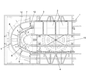
1. Transport system belt
2. Belt pallets
3. Transport system turn input
4. Transport system turn output
5. Turning system
6. Curved stretch of the turning system
7. External guide of the curved stretch
8. Internal guide of the curved stretch
9. Central chain
10. Drive wheel of the central chain
11. Central guide
12. Turning system carts
13. Arm joining the carts to the pallets
14. Cart wheels
15. Internal face of the central guide
16. External face of the central guide
Detailed description of the invention
CA 02896148 2015-06-22
WO 2014/102040 PCT/EP2013/075347
4
The object of the present invention is a turning system for a belt transport
system
1, of the variety formed by a plurality of pallets 2. The transport system has
a turn input
3 and a turn output 4, arranged on the same horizontal plane. The turning
system 5 has a
curved stretch 6, which connects the turn input 3 to the turn output 4. This
curved
stretch 6 is arranged on the same horizontal plane as the turn input 3 and as
the turn
output 4.
According to a specific embodiment of the invention, the curved stretch 6 of
the
turning system 5 is formed by an external guide 7, corresponding to the
external guide
of the turn input 3 and the turn output 4 and by an internal guide 8
corresponding to the
internal guide of the turn input 3 and the turn output 4, in such a way that
the pallets 2
of the belt 1 are arranged between the external guides 7 and internal guides
8, being
displaced along the length of the curved stretch 6 between the same.
In order to achieve this movement of the pallets 2 along the length of the
curved
stretch 6, the turning system 5 may have a central chain 9 to which the
pallets 2 are
joined and which drives the same in their journey. This central channel 9 is
arranged
between the external guide 7 and the internal guide 8 of the curved stretch 6.
According
to this embodiment and in a preferred way, the central channel 9 is arranged
on a
horizontal plane which is lower to the plane formed by the external guide 7
and the
internal guide 8 of the curved stretch 6. This central chain 9 is in turn
driven by a drive
wheel 10, which is coplanar to said central chain 9, although there may also
be
alternative ways to drive the central chain 9.
An alternative way to successfully move the pallets 2 along the length of the
curved stretch 6 is by means of a central guide 11 arranged between the
external guide 7
and the internal guide 8, in such a way that it is also arranged on a
horizontal plane
which is slightly lower than the plane formed by the external 7 and internal 8
guides of
the curved stretch 6. A number of carts 12 are displaced along the length of
this central
guide 11, each one of which is fixed to a pallet 2 on the belt 1. These carts
12 drag the
pallets 2 along the curved stretch 6, whilst the carts 12 are displaced along
the length of
the central guide 11, preferably being dragged by linear motors, although any
other
means may be used.
According to a preferred embodiment of the carts 12, the same are joined to
the
lower face of the pallets 2 by means of a joining arm 13.
Likewise, according to a preferred embodiment of the invention, the carts 12
are
joined to the central guide 11 and are displaced along the length of the same
by means
of a wheel 14 arranged on the internal face 15 of the central guide 11 and two
wheels 14
CA 02896148 2015-06-22
WO 2014/102040 PCT/EP2013/075347
arranged on the external face 16 of said central guide 11. Alternatively, the
carts 12 may
be joined to the central guide 11 and be displaced along the length of the
same by means
of four or more wheels.
After having described the invention clearly, it must be noted that details of
the
5 specific embodiments described above may be amended, provided that these
amendments do not change the fundamental principle and essence of the
invention.