Note: Descriptions are shown in the official language in which they were submitted.
CA 02896230 2015-07-08
1 WINDOW LAMINATED PACKAGE AND APPARATUS AND
2 METHODS OF MAKING THE SAME
3
4 CROSS-REFERENCE TO RELATED APPLICATIONS
This application claims priority to U.S. Provisional application serial no.
62/022,294
6 entitled WINDOW LAMINATED PACKAGE AND APPARATUS AND METHODS OF MAKING
7 SAME filed on July 9, 2014.
8 FIELD
9 This invention relates to printed articles such as product packages,
processes for the
iro manufacture of printed articles, and devices used to manufacture
printed articles.
11 SUMMARY
12 Aspects of the invention relate to product packages and printed
articles, as well as
13 devices and processes for producing product packages and/or printed
articles.
14 In accordance with one aspect, the invention provides a method for
producing a product
package having one or more laminated window portions. The method includes the
steps of
16 supplying a web of packaging material to an inline process including one
or more printing
17 stages, one or more cutting stages, and a lamination stage, the web of
packaging material
18 having a lamination side and an opposing non-lamination side; printing
one or more images on
19 the lamination side of the web of packaging material; cutting one or
more window apertures into
the web of packaging material; and laminating the lamination side of the web
of packaging
21 material to form the product package, the lamination side forming the
exterior of the product
22 package and the non-lamination side forming the interior of the product
package.
23 In accordance with another aspect, the invention provides a product
packaging obtained
24 according to any of the inventive methods. In one embodiment, the
invention provides a
product package. The product package includes a layer of packaging material
having a
26 lamination side, an opposing non-lamination side forming an interior of
the product package,
27 and one or more apertures. A layer of laminate is disposed on the
lamination side of the layer
28 of packaging material, the layer of laminate forming an exterior surface
of the product package
29 and covering the one or more apertures to form one or more viewable
windows. A layer of ink is
disposed between the layer of laminate and the layer of packaging material.
31 In accordance with yet another aspect, the invention provides an
apparatus for
32 producing a product package having one or more laminated window
portions. The apparatus
- 1 -
22759511.1
CA 02896230 2015-07-08
1 includes a plurality of inline stations which include one or more
printing stations configured to
2 print upon a lamination side of a web of packaging material; one or more
die cutting stations
3 configured to die cut one or more window apertures in the web of
packaging material; and a
4 lamination station configured to laminate a film to the lamination side
of the web of packaging
material.
6 In accordance with still another aspect, the invention provides a
method of producing a
7 printed article having one or more covered window portions. The method
includes the steps of
8 passing a blank through at least one printing station to print one or
more images on a first side
9 of the blank; passing the blank through at least one die cutting station
that is inline with the at
io least one printing station; die cutting one or more window apertures in
the blank at the at least
ii one die cutting station; passing the blank through at least one
lamination station that is inline
12 with the at least one printing station and the at least one die cutting
station; and applying a film
13 over the first side of the blank at the at least one lamination station
to cover the one or more
14 window apertures and at least a portion of the first side of the blank
with the film.
In accordance with still another aspect, the invention provides a printed
article obtained
16 according to any of the inventive methods.
17 In accordance with still another aspect, the invention provides an
apparatus for
18 producing a printed article having one or more covered window portions.
The apparatus
19 includes one or more printing stations operable to print one or more
images on a material. One
or more die cutting stations are inline with the one or more printing
stations, and the one or
21 more die cutting stations are operable to die cut one or more window
apertures in the material.
22 A lamination station is inline with the one or more printing stations
and the one or more die
23 cutting stations, and the lamination station is operable to laminate a
film over the one or more
24 images printed on the material.
In accordance with still another aspect, the invention provides a method for
producing a
26 product package having one or more laminated window portions. The method
includes the
27 steps of supplying a web of packaging material to an inline process
including one or more
28 cutting stages and a lamination stage, the web of packaging material
having a lamination side
29 and an opposing non-lamination side; cutting one or more window
apertures into the web of
packaging material; and laminating the lamination side of the web of packaging
material to form
31 the product package, the lamination side forming the exterior of the
product package and the
32 non-lamination side forming the interior of the product package.
-2-
22759511.1
CA 02896230 2015-07-08
1 It is to be understood that both the foregoing general description and
the following
2 detailed description are exemplary, but are not restrictive, of the
invention.
3 BRIEF DESCRIPTION OF THE DRAWINGS
4 The invention is best understood from the following detailed
description when read in
connection with the accompanying drawings, with like elements having the same
reference
6 numerals. When a plurality of similar elements are present, a single
reference numeral may be
7 assigned to the plurality of similar elements with a small letter
designation referring to specific
8 elements. When referring to the elements collectively or to a non-
specific one or more of the
9 elements, the small letter designation may be dropped. This emphasizes
that according to
io common practice, the various features of the drawings are not drawn to
scale unless otherwise
ii indicated. On the contrary, the dimensions of the various features may
be expanded or reduced
12 for clarity. Included in the drawings are the following figures:
13 FIG. lA is a schematic illustration of a product package according to
aspects of the
14 present invention;
FIG. 1B is a photograph of a product package according to aspects of the
present
16 invention
17 FIG. 2 is a flow diagram of a method for producing a product package
having one or
18 more laminated window portions according to aspects of the present
invention;
19 FIG. 3 is a schematic illustration of an apparatus for producing a
product package having
one or more laminated window portions according to aspects of the present
invention; and
21 FIG. 4 is a flow diagram of a method for producing a printed article
having one or more
22 covered window portions according to aspects of the present invention.
23 DETAILED DESCRIPTION OF THE INVENTION
24 Aspects of the invention relate to product packages and printed
articles, as well as
devices and processes for producing product packages and/or printed articles.
26 The inventors have recognized that it would be useful to provide for an
inline process
27 and apparatus for the production of product packages for consumer goods
such as foodstuffs,
28 medical and pharmaceutical products, electronic products, and others. As
used herein, an
29 "inline" process is a process in which the web of packaging material may
be continuously moved
throughout the stages or stations of the inline process. In an inline process,
the web of
-3-
22759511.1
CA 02896230 2015-07-08
1 packaging material may pass through each stage or station without
interruption (e.g., the web of
2 packaging material may move directly from one or more die cutting stages
to a lamination stage
3 without stopping the inline process). It should be understood that an
inline process does not
4 require that the web of packaging material move continuously through the
inline process, but
only requires that the stages or stations of the inline process be
configurable to continuously
6 move the web of packaging material.
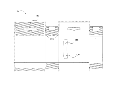
7 Turning to FIG. 1A, an unassembled product package 100 according to one
aspect of
8 the present invention is provided. Unassembled product package 100 is
formed of a composite
9 sheet material which includes an exterior surface 110. Exterior surface
110 is the surface of the
product package which, upon assembly of the product package as shown by FIG.
1B, is
11 presented to and viewable by, e.g., a consumer.
12 Turning back to FIG. 1A, exterior surface 110 is formed of a layer of
laminate. The layer
13 of laminate may be formed of a transparent plastic film material.
Exemplary laminates include
14 films of, e.g., polyethylene, polypropylene, polyester, and mixtures
thereof. In one embodiment,
the layer of laminate may be formed of a film of oriented poly-propylene
("oPP") or polyethylene
16 terephthalate.
17 The layer of laminate may be layered on top of a layer of ink printed
on a lamination side
18 of a layer of packaging material. In one embodiment, the layer of
laminate is extruded onto or
19 adhered to the lamination side of a layer of packaging material. The
layer of laminate may be
adhered via a layer of adhesive. Exemplary adhesives include pressure
sensitive adhesives
21 and energy curable adhesives.
22 The layer of ink may be deposited on the layer of packaging material
through any known
23 means including, e.g., one or more stages of flexographic printing.
24 The layer of packaging material also includes a non-lamination side
which forms the
interior of product package 100. The layer of packaging material may be formed
of a non-
26 transparent material such as paper, metalized polymer film, aluminum
foil, or boxboard.
27 Unassembled product package 100 includes an aperture 115 which may be
cut from the
28 layer of packaging material. Preferably, aperture 115 is cut from the
layer of packaging material
29 prior to the application of the layer of laminate, as is more fully
described below with respect to
the inventive processes.
-4-
22759511.1
CA 02896230 2015-07-08
1 While one of ordinary skill will understand that the layer of laminate
may extend across
2 less than all of exterior surface 110, the layer of laminate desirably
extends completely across
3 aperture 115 to form viewable window 120. Viewable window 120 provides,
e.g., a consumer
4 with the ability to view the contents of product package 100 once
assembled through the layer
of laminate, which can be transparent. Turning briefly to FIG. 1B, viewable
window 120 permits
6 an end user to visually inspect the contents of product package 100 and,
e.g., determine the
7 amount of remaining product 122. The amount of remaining product 122,
here cat litter, is
8 viewable through viewable window 120. A product housed in product
packaging 100 thus has
9 additional shelf appeal and generates increased consumer interest over
other product
packaging.
11 The inventors have also found that, by providing the layer of laminate
on the exterior
12 surface of the product packaging, an enhanced moisture vapor
transmission rate ("MVTR") may
13 be achieved. That is, the exterior layer of laminate reduces the amount
of moisture transmitted
14 to the interior of product packaging (where the product resides) as
compared to product
packaging having a film adhered to the interior of the product packaging.
Moisture sensitive
16 products, such as moisture sensitive foods, packaged in the inventive
product packaging thus
17 achieve enhanced quality, safety, and shelf life.
18 The shape of viewable window 120 is depicted as a crescent in FIGs la
and lb for
19 illustrative purposes. One of ordinary skill in the art will understand
that viewable window 120
may take any known two-dimensional regular or irregular shape such as, without
limitation, a
21 circle, rectangle, square, polygon, etc. The shape of viewable window
120 may be controlled by
22 the shape of the aperture cut out of the layer of packaging material.
23 One of ordinary skill in the art will further understand that, while a
single viewable
24 window 120 is depicted in FIGs la and 1 b, the invention is not so
limited. Indeed, a plurality of
viewable windows may be located on a single product packaging according to the
present
26 invention.
27 Turning to FIG. 2, a flow diagram depicting selected steps of a process
200 for
28 producing a product package having one or more laminated window portions
according to
29 aspects of the invention is shown. It should be noted that, with respect
to the methods
described herein, it will be understood from the description herein that one
or more steps may
31 be omitted and/or performed out of the described sequence of the method
(including
32 simultaneously) while still achieving the desired result. In addition,
it will be understood that
-5-
22759511.1
CA 02896230 2015-07-08
1 other steps, not described herein but known to persons skilled in the
art, can be performed in
2 processes according to the invention, while still achieving the desired
result.
3 Certain elements of process 200 are illustrated in FIG. 3, which
depicts a schematic of
4 an apparatus for producing a product package having one or more laminated
window portions.
For clarity of understanding, and without any intention of limiting process
200 to the apparatus
6 shown in FIG. 3, process 200 will be described below with respect to the
apparatus of FIG. 3.
7 In step 210, a web of packaging material 315 is supplied from an unwind
roller 310 to an
8 inline process 300. Inline process 300 may include one or more printing
stages 320, one or
9 more die cutting stages 340, and one or more lamination stages 360. The
inline process may
io be a single apparatus or may be multiple apparatuses configured to
continuously move web of
ii packaging material 315. The inventors have found that the use of an
inline process desirably
12 reduces production time, especially where, as with inline processes,
processing of the web of
13 packaging material does not need to stop to physically transfer the web
of packaging material
14 from one stage to the next.
Web of packaging material 315 is a web or sheet-shaped material in the form of
long
16 sheets or rolls which are subsequently shaped into containers and
filled. Web of packaging
17 material 315 forms at least one layer of a product package and may be
comprised of, e.g., a
18 non-transparent material such as paper, metalized polymer film, or
aluminum foil. Web of
19 packaging material 315 typically includes a lamination side and an
opposing non-lamination
side.
21 In step 220, one or more images or indicia are printed on the
lamination side of web of
22 packaging material 315. The images may be deposited on web of packaging
material 315
23 through one or more printing stages 320 which employ any known means for
printing images
24 onto webs of packaging materials including, e.g., one or more stages of
flexographic printing.
One of ordinary skill in the art will understand that several stages of
flexographic printing may be
26 desirable for a given web of packaging material. In one embodiment, the
inline process
27 includes seven or more flexographic printing stages.
28 After one or more printing stages, the location of apertures to be cut
into web of
29 packaging materials may be registered by registry 330. Synchronization
marks resulting from
the one or more printing stages may be detected by an optical sensor, which
identifies a
31 location or locations of one or more apertures to be cut.
Synchronization marks may also be
-6-
22759511.1
CA 02896230 2015-07-08
1 used at a later stage for cutting composite packaging material to form
the unit product
2 packages.
3 In step 230, one or more window apertures are cut into web of packaging
material 315.
4 Die cutting may be performed at one or more die cutting stages 340. As
described above, the
shape of the viewable window on the resulting product packaging corresponds to
the shape of
6 the aperture cut out of the layer of packaging material. Die cutting
stage 340 may be configured
7 with a die cutting tool associated with the desired shape of aperture.
Thus, a variety of aperture
8 (and the associated viewable window) shapes may be achieved as described
above. Further,
9 one of ordinary skill in the art will understand that, in addition to die
cutting, other cutting means
io such as laser cutting or water jet cutting may be employed.
11 Die cutting stage 340 may also include the removal of the resulting
excess packaging
12 material. Removal may occur through any means known to one of ordinary
skill in the art,
13 including a vacuum/pressure roll over which retains the excess packaging
material on the roll
14 surface after the die cut packaging material passes off the roll.
Alternatively, a rotary pin
mechanism can be used to remove excess packaging material.
16 In step 240, the lamination side of the web of packaging material is
laminated to form the
17 product package, such that the lamination side forms the exterior of the
product package and
18 the non-lamination side forms the interior of the product package.
Depending on the number of
19 apertures per product package, each resulting product package may have
one, two, or more
laminated window portions. Lamination may be performed at one or more
lamination stages
21 360. Step 240 may include applying a web of film material as a laminate.
Suitable laminates
22 include, e.g., polyethylene, polypropylene, polyester, and mixtures
thereof. In one embodiment,
23 the laminate may be formed of a film of oriented poly-propylene ("oPP")
or polyethylene
24 terephthalate.
The web of film material may be adhered to the lamination side of the web of
packaging
26 material 315 through a coating of adhesive. The coating of adhesive may
be applied to either
27 the web of film material or the lamination side of the web of packaging
material 315. Exemplary
28 adhesives include pressure sensitive adhesives. In one embodiment, the
layer of laminate is
29 extruded onto or adhered to the lamination side of the web of packaging
material 315.
The web of film material may be joined to web of packaging material 315
through a nip
31 roller (not shown) to produce a web of composite packaging material 365.
-7-
22759511.1
CA 02896230 2015-07-08
1 The web of composite packaging material 365 exiting the one or more
lamination stages
2 360 is then advanced to rewind roller 370 and spooled for subsequent use.
3 In accordance with another aspect, the invention provides a product
packaging obtained
4 according to any of the inventive methods.
Turning to FIG. 4, a flow diagram depicting selected steps of a process 400
for
6 producing a printed article having one or more covered window portions in
accordance with the
7 present invention is depicted. In one embodiment, the printed article is
a product package.
8 In step 410, a blank is passed through at least one printing station to
print one or more
9 images or indicia on a first side of the bank. The blank may be a web or
sheet-shaped material
io in the form of long sheets or rolls which are subsequently shaped into
containers and filled. The
1.1 blank may be comprised of packaging material which forms at least one
layer of a product
12 package. The printed images or indicia can include synchronization
marks, as described
13 earlier, for subsequently identifying the location of apertures to be
cut in the next stage.
14 In step 420, the blank is passed through at least one die cutting
station that is in line with
the at least one printing station. At the die cutting station, one or more
window apertures are die
16 cut in the blank.
17 In step 430, the blank is passed through at least one lamination
station that is inline with
18 the at least one printing station and the at least one die cutting
station. At the lamination station,
19 a film is applied over the first side of the blank to cover the one or
more window apertures and
at least a portion of the first side of the blank. In one embodiment, the film
extends across the
21 one or more apertures. The film may be a clear transparent film. In one
embodiment, the step
22 of applying a film includes applying a moisture barrier over the one or
more window apertures.
23 The film may be adhered to the first side of the blank through a
coating of adhesive. The
24 coating of adhesive may be applied to either the film or the first side
of the blank. The coating of
adhesive may occur after the step of die cutting one or more window apertures
in the blank.
26 Although the invention is illustrated and described herein with
reference to specific
27 embodiments, the invention is not intended to be limited to the details
shown. Rather, various
28 modifications may be made in the details within the scope and range of
equivalents of the
29 claims and without departing from the invention.
-8-
22759511.1