Note: Descriptions are shown in the official language in which they were submitted.
CA 02896271 2015-06-23
WO 2014/109932
PCMJS2013/078375
SWAB ASSEMBLY FOR SPECIMEN COLLECTION
FIELD OF INVENTION
The invention pertain to devices used for biological specimen collection, and
more
particularly, to a swab assembly for collecting a biological specimen from a
urethra, a cervix,
or the like.
BACKGROUND
Currently, swabs are used for the collection of specimens to test for sexually
transmitted diseases, or other biological testing. Such swabs may be used to
collect
specimens from the urethra or the cervix of a patient. A specimen collection
swab may
include an elongated shaft and a collection tip made of a fibrous or foam
material. The
elongated shaft may include a scored area to facilitate breaking the shaft at
a desired height in
order to fit the shaft and collection tip into a standard collection tube
after the sample is
obtained from the patient. However, a disadvantage associated with these
collection swabs is
that the scored area may cause the swab to prematurely break at the scored
area during the
sample collection process. Patient discomfort when collecting a specimen using
the known
collection swabs is also a problem.
SUMMARY
In accordance with one embodiment of the invention, a swab assembly for
collecting
a specimen from a patient is provided. The swab assembly may be sized and
shaped for
being inserted into a urethra or a cervix. In one embodiment, the swab
assembly includes an
elongated shaft having a proximal end and a distal end, the elongated shaft
having a notch
therein between its proximal and distal ends, such that the elongated shaft
preferentially
breaks at the notch when a force is applied to the elongated shaft. The swab
assembly further
includes a sheath having a proximal end and a distal end, the sheath defining
a lumen
extending between its proximal and distal ends, wherein at least a portion of
the elongated
shaft is disposed within the sheath lumen, with the sheath being slidable
relative to the
elongated shaft. A collection tip is coupled to the distal end of the
elongated shaft and
configured for obtaining the specimen. The elongated shaft may include a
protrusion located
proximally relative to the collection tip, wherein the protrusion is
configured for preventing
the sheath from moving over the collection tip. Alternatively, the sheath may
be configured
for covering the collection tip, such that the collection tip is compressed
and disposed within
the sheath lumen.
1
The sheath is slidable between a first position in which the shaft notch is
disposed
within the sheath lumen and wherein the sheath protects the elongated shaft
from breaking at
the notch, and a second position in which the shaft notch is exposed out of
the sheath lumen,
and wherein the sheath does not protect the elongated shaft from breaking at
the notch. A
length of the sheath may be less than a length of the elongated shaft, such
that the elongated
shaft extends through the entire length of the sheath lumen when the sheath is
in the first
position and in the second position. The collection tip may remain outside of
the sheath
lumen when the sheath is in the first position and in the second position.
In accordance with another embodiment of the invention, a method for
collecting a
specimen from a patient using the swab assembly is provided. The method
includes the steps
of inserting the swab assembly into a body lumen (e.g., a urethra or a cervix)
of the patient
until the collection tip is adjacent to a target collection site; obtaining
the specimen by
contacting the target collection site with the collection tip; removing the
swab assembly from
the body lumen, wherein the elongated shaft is disposed within the sheath
lumen such that the
notch remains positioned in the sheath lumen during the inserting, obtaining,
and removing
steps; sliding the sheath relative to the elongated shaft, or sliding the
elongated shaft relative
to the sheath, such that the shaft notch is disposed outside of the sheath
lumen; and breaking
the elongated shaft at or proximate the notch. The collection tip may be
positioned distally
relative to the sheath during all steps of the method. Alternatively, the
method may include a
further step of, before the step of obtaining the specimen, exposing the
collection tip by
sliding the sheath relative to the elongated shaft, or sliding the elongated
shaft relative to the
sheath, such that the notch remains positioned in the sheath lumen. It should
be appreciated
that the swab may be more easily inserted when the fibrous or foam tip is
covered by the
smooth sheath, due to reduced patient discomfort. Once inserted, the sheath is
pulled back,
exposing the tip for specimen collection.
Other and further embodiments and features of the invention will be evident
from
reading the following detailed description of embodiments thereof, which are
intended to
illustrate, not limit, the claimed invention.
Accordingly, in one aspect the present invention resides a in swab assembly
for
collecting a specimen from a human urethra, comprising: an elongated shaft
having a
proximal end and a distal end, the elongated shaft having a notch therein
between its
proximal and distal ends; a sheath having a proximal end and a distal end, the
sheath defining
a lumen extending between its proximal and distal ends, wherein at least a
portion of the
elongated shaft is disposed within the sheath lumen, and the sheath is
slidable relative to the
2
CA 2896271 2018-08-13
elongated shaft, the sheath being sized and shaped for insertion into a human
urethra; and a
compressible collection tip coupled to the distal end of the elongated shaft
and configured for
obtaining the specimen, wherein the sheath is slidable between a first
position in which the
shaft notch is disposed within the sheath lumen and wherein the sheath
protects the elongated
shaft from breaking at the notch, and a second position in which the shaft
notch is exposed
out of the sheath lumen, and wherein the sheath does not protect the elongated
shaft from
breaking at the notch, and wherein the collection tip is configured to be
compressed and
positioned entirely within the sheath lumen during insertion of the sheath
into the urethra, and
wherein the collection tip expands when the collection tip is exposed out of
the sheath lumen
when the sheath is positioned at or near a specimen collection site within the
urethra.
In another aspect the present invention resides in a method for collecting a
specimen
from a human urethra using a swab assembly comprising a sheath having a lumen,
an
elongated shaft disposed within the sheath lumen, and a compressible
collection tip coupled
to a distal end of the elongated shaft, wherein the elongated shaft comprises
a notch
configured to cause the elongated shaft to preferentially break at the notch
when a force is
applied to the elongated shaft, the method comprising the steps of: inserting
the swab
assembly into a human urethra until the collection tip is adjacent to a target
collection site,
wherein the collection tip is compressed and positioned within the sheath
lumen during the
inserting step; exposing the collection tip within the urethra by sliding the
sheath relative to
the elongated shaft, or sliding the elongated shaft relative to the sheath,
such that the notch
remains positioned in the sheath lumen, wherein the collection tip expands
when exposed out
of the sheath lumen; obtaining the specimen by contacting the target
collection site with the
collection tip; removing the swab assembly from the urethra, wherein the
elongated shaft is
disposed within the sheath lumen such that the notch is positioned in the
sheath lumen during
the inserting, obtaining, and removing steps; sliding the sheath relative to
the elongated shaft,
or sliding the elongated shaft relative to the sheath, such that the shaft
notch is disposed
outside of the sheath lumen; and breaking the elongated shaft at or proximate
the notch.
BRIEF DESCRIPTION OF THE DRAWINGS
The drawings illustrate the design and utility of embodiments of the
invention, in
which similar elements are referred to by common reference numerals, and in
which:
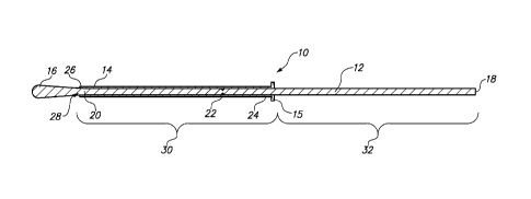
Fig. 1 is a cross-sectional view of a swab assembly in accordance with one
embodiment, with a sheath in a first position;
2a
CA 2896271 2018-08-13
CA 02896271 2015-06-23
WO 2014/109932
PCT/US2013/078375
Fig. 2 is a cross-sectional view of the swab assembly in Fig. 1 with the
sheath in a
second position;
Fig. 3 is a cross-sectional view of a distal end of the swab assembly, in
accordance
with another embodiment;
Fig. 4 is a cross-sectional view of the swab assembly in accordance with yet
another
embodiment, with the sheath disposed over a collection tip; and
Fig. 5 is a flow chart illustrating a method for collecting a specimen using
the swab
assembly, in accordance with still another embodiment.
DETAILED DESCRIPTION OF THE ILLUSTRATED EMBODIMENTS
Turning first to Fig. 1, an exemplary swab assembly 10 for collecting a
specimen
from a patient is shown. The swab assembly 10 may be sized and shaped for
being inserted
into a urethra or a cervix. The swab assembly 10 may be used for collecting
cellular material
that may be used to test for sexually transmitted diseases. The swab assembly
10 is
preferably configured for collecting a specimen, while avoiding premature
breakage.
The swab assembly 10 generally includes an elongated shaft 12, a sheath 14,
and a
collection tip 16. The elongated shaft 12 has a proximal end 18, a distal end
20, and a notch
22 between the proximal and distal ends 18, 20. The elongated shaft 12 is
configured to
preferentially break at the notch 22 when a force is applied to the elongated
shaft 12.
The collection tip 16 is coupled to the distal end 20 of the elongated shaft
12, and is
configured for obtaining the specimen. The collection tip 16 may be made of a
fibrous or
foam material. For example, the collection tip 16 may be similar to a
collection tip of a
cotton swab.
The sheath 14 has a proximal end 24 and a distal end 26. A sheath lumen 28
extends
between the proximal and distal ends 24, 26 of the sheath 14. The sheath 14
may be made of
a biocompatible material, and may have a low-friction external surface in
order to minimize
patient discomfort during insertion into a body lumen of the patient.
A portion of the elongated shaft 12 is disposed within the sheath lumen 28,
and the
sheath 14 is slidable relative to the elongated shaft 12. In particular, the
sheath 14 is slidable
between a first position, shown in Fig. 1, and a second position, shown in
Fig. 2. When the
sheath 14 is in the first position, the shaft notch 22 is disposed within the
sheath lumen 28.
Thus, the sheath 14 protects the elongated shaft 12 from breaking at the notch
22 when the
sheath 14 is in the first position shown in Fig. 1. When the sheath 14 is in
the second
position, the shaft notch 22 is exposed outside of the sheath lumen 28. Thus,
the sheath 14
3
CA 02896271 2015-06-23
WO 2014/109932
PCT/1JS2013/078375
does not protect the elongated shaft 12 from breaking at the notch 22 when the
sheath 14 is in
the second position shown in Fig. 2.
In the embodiment shown in Figs. 1 and 2, the first position is a distal
position and
the second position is a proximal position. However, it should be well
understood that,
depending on the location of the notch 22, the length of the sheath 14, and/or
the length of the
elongated shaft 12, the sheath 14 may alternatively be in a proximal position
or an
intermediate position when the shaft notch 22 is disposed within the sheath
lumen 28. In
general, the sheath 14 is slidable between a position where the shaft notch 22
is covered by
the sheath 14 and a position where the shaft notch 22 is disposed outside of
the sheath 14.
The sheath 14 includes an enlarged handle portion 15 on the proximal end 24 of
the
sheath 14. The handle portion 15 may be grasped by the user when sliding the
sheath 14
relative to the elongated shaft 12. Thus, the handle portion 15 facilitates
sliding the sheath 14
back and forth on the elongated shaft 12. Alternatively, the sheath 14 does
not include a
handle portion 15, and instead has a constant outer diameter along its entire
length. In this
embodiment, the user may grasp the outer surface of the sheath 14 in order to
the slide the
sheath 14 relative to the elongated shaft 12.
The length of the sheath 14 is less than the length of the elongated shaft 12.
As such,
the elongated shaft 12 extends through the entire length of the sheath lumen
28 when the
sheath 14 is in the first position and in the second position. In the example
shown in Figs. 1
and 2, a distal portion 30 of the elongated shaft 12 is disposed within the
sheath lumen 28
when the sheath 14 is in the first position, and a proximal portion 32 of the
elongated shaft 12
is disposed within the sheath lumen 28 when the sheath 14 is in the second
position. The
distal portion 30 of the elongated shaft 12 includes the notch 22, and the
proximal portion 32
of the elongated shaft 12 does not include the notch 22.
In one embodiment, the elongated shaft 12 may include a positive engagement
feature
for limiting the movement of the sheath 14 relative to the elongated shaft 12.
For example, as
shown in Fig. 3, the elongated shaft 12 includes a protrusion 34 located
proximally relative to
the collection tip 16. The protrusion 34 is configured for preventing the
sheath 14 from
moving over the collection tip 16. Similarly, the elongated shaft 12 may
include a protrusion
in other locations along the length of the elongated shaft 12 in order to
limit proximal or
distal movement of the sheath 14 relative to the elongated shaft 12.
In the embodiments shown in Figs. 1-3, the collection tip 16 remains outside
of the
sheath lumen 28 whether the sheath 14 is in the first position or the second
position.
4
CA 02896271 2015-06-23
WO 2014/109932
PCT/US2013/078375
Alternatively, the sheath 14 may be configured for being positioned over the
collection tip 16,
as shown in Fig. 4. In this embodiment, the sheath 14 may be slidable between
three
different positions. In the first sheath position, shown in Fig. 4, the
collection tip 16 and the
shaft notch 22 are positioned within the sheath lumen 28 while the swab
assembly 10 is being
inserted through a body lumen (e.g., a urethra, cervix, or the like). In the
second sheath
position, shown in Fig. 1, the collection tip 16 is disposed outside of the
sheath lumen 28, and
the shaft notch 22 is positioned within the sheath lumen 28 while the specimen
is being
collected on the collection tip 16. In the third sheath position, shown in
Fig. 2, the collection
tip 16 and the shaft notch 22 are positioned outside of the sheath lumen 28
after the specimen
is collected so that the elongated shaft 12 can be broken at the notch 22
before being
deposited into a sample tube. In the embodiment shown in Fig. 4, the sheath 14
compresses
the collection tip 16 while the swab assembly 10 is inserted through the body
lumen. Thus,
the effective outer diameter of the swab assembly 10 is reduced in order to
minimize patient
discomfort during insertion through the body lumen of the patient. After the
swab assembly
10 is positioned at or near the specimen collection site, the sheath 14 is
moved proximally
relative to the elongated shaft 12 and the collection tip 16 is deployed and
expanded.
A method 100 for collecting a specimen from a patient using the swab assembly
10 is
depicted in the flow chart shown in Fig. 5. In a first step 102, the swab
assembly 10 is
inserted into a body lumen of the patient until the collection tip 16 is
adjacent to a target
collection site. The body lumen may be, for example, a cervix or a urethra.
Next, in step
104, the specimen is obtained by contacting the target collection site with
the collection tip
16. The swab assembly 10 is then removed from the body lumen in step 106. The
elongated
shaft 12 is disposed within the sheath lumen 28 such that the notch 22 is
positioned in the
sheath lumen 28 during steps 102, 104, and 106. Next, in step 108, the sheath
14 is slid
relative to the elongated shaft 12, or the elongated shaft 12 is slid relative
to the sheath 14,
such that the shaft notch 22 is disposed outside of the sheath lumen 28, as
shown in Fig. 2.
Finally, in step 110, the elongated shaft 12 is broken at or proximate the
notch 22. In one
embodiment of the method 100, the collection tip 16 is positioned distally
relative to the
sheath 14 during all steps of the method.
In another embodiment of the method 100, the collection tip 16 is positioned
within
the sheath lumen 28, as shown in Fig. 4, while the swab assembly 10 is
inserted into the body
lumen in step 102. In this embodiment, the method includes a step 103 of,
before collecting
the specimen, sliding the sheath 14 relative to the elongated shaft 12, or
sliding the elongated
5
CA 02896271 2015-06-23
WO 2014/109932
PCT/US2013/078375
shaft 12 relative to the sheath 14, such that the collection tip 16 is
disposed outside of the
sheath lumen 28 while the shaft notch 22 remains within the shaft lumen 28.
Again, because the fibrous or foam tip is covered by the smooth sheath during
insertion, the patient experiences less discomfort. Once inserted, the sheath
is pulled back,
exposing the tip for specimen collection.
6