Note: Descriptions are shown in the official language in which they were submitted.
CA 02896276 2015-06-23
WO 2014/163710 PCT/US2013/078489
-1-
SEAL ASSEMBLY AND SHAFT THEREFOR
CROSS REFERENCE TO RELATED APPLICATIONS
[0001] This application claims priority to and the benefit U.S.
Provisional Patent
Application Number 61/774,436, filed on March 7, 2013, the disclosure of which
is now
expressly incorporated herein by reference.
TECHICAL FIELD
[0002] The present application relates to a seal assembly and, more
particularly,
but not exclusively, to a shaft having surface geometric characteristics that
interact
with a shaft seal.
BACKGROUND
[0003] Providing a buffer of fluid such as air and/or oil to interfaces
of sealing
surfaces, for example between a shaft and a shaft seal, remains an area of
interest.
Some existing systems have various shortcomings, drawbacks, and disadvantages
relative to certain applications. Accordingly, there remains a need for
further
contributions in this area of technology.
SUMMARY
[0004] One embodiment of the present application is a fluid sealing
assembly
that includes a shaft having a microstructural geometry that generates a
pressure
differential at an interface with a seal to push or pull fluid relative to the
interface.
[0005] Other embodiments include unique methods, systems, devices, and
apparatus to provide for micro pump interaction at the interface of a shaft
geometry
and a shaft seal. Further embodiments, forms, objects, aspects, benefits,
features, and
advantages of the present application shall become apparent from the
description and
figures provided herewith.
BRIEF DESCRIPTION OF THE FIGURES
[0006] Features of the application will be better understood from the
following
detailed description when considered in reference to the accompanying
drawings, in
which:
CA 02896276 2015-06-23
WO 2014/163710 PCT/US2013/078489
-2-
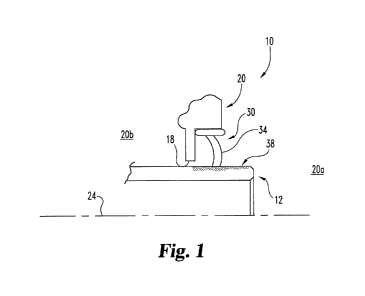
[0007] Fig. 1 shows a cross-section of a seal assembly according to an
embodiment;
[0008] Fig. 2 shows a shaft and a shaft geometry according to an
embodiment,
enlarged to show the microstructural geometry in the surface of the shaft;
[0009] Fig. 3 shows a cross-section of a localized portion of the Fig. 2
shaft, as
seen from the line 3-3 in Fig. 2, and enlarged to show the microstructural
geometry in
the surface of the shaft;
[0010] Fig. 4 shows the microstructural geometry in the surface of the
Fig. 2
shaft;
[0011] Fig. 5A and 5B show a microstructural geometry comprising slots
having
a positive slope and slots having a negative slope, respectively; and
[0012] Fig. 6 shows a flowchart of a method according to an embodiment.
DETAILED DESCRIPTION
[0013] While the present invention can take many different forms, for the
purpose of promoting an understanding of the principles of the invention,
reference will
now be made to the embodiments illustrated in the drawings and specific
language will
be used to describe the same. It will nevertheless be understood that no
limitation of
the scope of the invention is thereby intended.
Any alterations and further
modifications of the described embodiments, and any further applications of
the
principles of the invention as described herein, are contemplated as would
normally
occur to one skilled in the art to which the invention relates.
[0014] Fig. 1 shows a seal assembly 10 according to an embodiment. The
seal
assembly 10 can be used in any suitable application in which a shaft 12
extends
through an opening 18 in a housing 20 and moves relative to the housing 20 for
example by rotation about and/or translation along an axis 24. In one
embodiment, the
housing 20 comprises a housing of an accessory drive gearbox of an aircraft
gas
turbine engine, which transmits power from a shaft of the gas turbine engine
to various
components of the aircraft such as propellers, fuel pumps, hydraulic pumps,
electric
generators, etc. The seal assembly 10 is not limited to aircraft applications,
and other
embodiments are contemplated. For example, the seal assembly 10 can be
utilized in
industrial applications, power generation applications, pumping sets, naval
propulsion
and other applications known to one of ordinary skill in the art. Further, it
will be
CA 02896276 2015-06-23
WO 2014/163710 PCT/US2013/078489
-3-
appreciated that the term "aircraft" as used herein includes, but is not
limited to,
helicopters, airplanes, unmanned space vehicles, fixed wing vehicles, variable
wing
vehicles, rotary wing vehicles, unmanned combat aerial vehicles, tailless
aircraft, hover
crafts, and other airborne and/or extraterrestrial (spacecraft) vehicles.
[0015] The seal assembly 10 includes a shaft 12 and an annular shape seal
30
that can interact with each other to prevent or inhibit the passage of fluid
through the
interface of the shaft 12 and the inside diameter of the opening 18 in the
housing 20,
thus sealing for example the outside 20a of the housing 20 from the inside 20b
of the
housing 20. The shaft 12 can include metallic and/or non-metallic materials,
for
example, stainless steel, aluminum, titanium, and/or or a ceramic composite,
for
example. The seal 30 can include elastomeric materials, including natural
rubber
and/or synthetic rubber, polymeric materials, and/or composite materials, for
example.
The configuration of the seal 30 is based on the sealing requirements of an
application,
including consideration of for example the characteristics of fluid being
sealed from
passing through the opening 18, the material properties and configuration of
the shaft
12 and the housing 20, and the pressure, temperature, and other environmental
demands of the application. In the illustrative embodiment, the seal 30
comprises a
seal having a radially flexible portion, such as a lip seal. The lip seal 30
serves to
prevent or inhibit flow by pressing a lip portion 34 against and/or in close
proximity to
the rotating and/or translating shaft 12. The as-shown seal 30 comprises a
single lip; in
another form, the seal 30 can comprise a multiple lip design. In one form, the
seal 30
can include a garter spring disposed in a recess within the body of the seal
30 and
radially outside the lip portion 34 of the seal 30, to urge the seal 30 to a
particular
proximity relative to the housing 20 and/or shaft 12. In another form, the
seal 30 can
include a circumferential alignment ring that aligns the body of the seal 30
circumferentially with respect to the housing 20 and/or the shaft 12.
[0016] The shaft 12 and seal 30 interact to push or pull fluid such as
air and/or
oil at the interface of, or clearance between, the shaft 12 and seal 30. In
the FIG. 1
embodiment, at the circumferential portion at which the shaft 12 and seal 30
interface,
the shaft 12 includes a microstructural geometry 38 in its surface. The
microstructural
geometry 38 can include for example an arrangement of micro channels and/or
micro
grooves in the surface of the shaft 12. During rotation of the shaft 12, the
microstructural geometry 38 can interact with the seal 30 to generate a
localized fluid
CA 02896276 2015-06-23
WO 2014/163710 PCT/US2013/078489
-4-
pressure differential having the effect of a micro fluid pump. In one
embodiment, the
localized fluid pressure differential, or micro fluid pump, serves to pump a
buffer of fluid
across the seal 30. Other embodiments are also contemplated. For example, in
an
embodiment, the micro fluid pump can additionally or alternatively serve to
pump a
buffer of fluid between the surfaces of the shaft 12 and seal 30 to
aerodynamically
and/or hydrodynamically lift off the seal 30 from the outside diameter of the
shaft 12. In
another embodiment, the micro fluid pump can additionally or alternatively
serve to add
a buffer fluid into the interface of the shaft 12 and seal 30. In a further
embodiment, the
micro fluid pump can additionally or alternatively serve to remove buffer
fluid from the
interface of the shaft 12 and seal 30.
[0017] Figs. 2 through 5 show a shaft 12 and a shaft microstructural
geometry
38 according to an embodiment. In the illustrative embodiment, the shaft 12
has a
microstructural geometry 38 in its surface that comprises a plurality of
circumferentially
spaced apart angled grooves or slots 40 formed for example by etching, to be
described in greater detail below. Fig. 3 shows the depth D of the slots 40.
The depth
D can be substantially the same for all slots 40, as shown, or can differ from
slot 40 to
slot 40, or amongst different groups of slots 40, depending on the particular
application
of the seal assembly 10. Figs. 2, 4, 5A, and 5B, show the angle alpha (a) at
which the
slots 40 are disposed relative to a plane P perpendicular to the axis 24 of
the shaft 12.
The angle a can depend on the direction of rotation of the shaft 12 and
whether the
seal assembly 10 is to seal the inside 20b or outside 20a of the housing 20.
For
example, for a given direction of shaft 12 rotation, for example clockwise,
the slots 40
shown in the Fig. 5A microstructural geometry 38 have a positive slope to
generate a
micro pump action from the outside 20a to the inside 20b of the housing 20,
whereas
the slots 40 shown in the Fig. 5B microstructural geometry 38 have a negative
slope to
generate a micro pump action from the inside 20b to the outside 20a of the
housing 20.
Although the angle a is shown as being substantially the same for all slots
40, the
microstructural geometry 38 need not be limited as such. Thus, for example,
some
slots 40 can be disposed at a first angle and some slots 40 disposed at a
second angle
that is different from the first angle.
[0018] Fig. 4 shows an enlarged localized portion of the microstructural
geometry 38. As shown, the slots 40 are equally circumferentially spaced apart
by a
distance S. In another form, the slots 40 can be unequally spaced apart and/or
can
CA 02896276 2015-06-23
WO 2014/163710 PCT/US2013/078489
-5-
have a random distribution depending on the desired sealing and/or pumping
characteristics of the seal assembly 10. Further, in the illustrative
embodiment the slots
40 have the same width W and the same length L, although the microstructural
geometry 38 need not be limited as such. As with the depth D, the width W and
the
length L can differ from slot 40 to slot 40, or amongst different groups of
slots 40,
depending on the particular application of the seal assembly 10. In the Fig. 4
embodiment, the slots 40 have a somewhat elongated shape in the axial
direction of
the shaft 12. The slots 40 can have any shape depending on the application of
the seal
assembly 10.
[0019] Any suitable manufacturing process for fabricating microstructural
parts
and components can be used to provide the microstructural geometry 38 in the
surface
of the shaft 12. In one embodiment, the microstructural geometry 38 is
manufactured
by way of a surface etching technique, for example, a chemical etching
technique or
electrochemical etching technique. Fig. 6 shows a flowchart of a method of
fabricating
a microstructural geometry 38 into the surface of a shaft 12 according to an
embodiment. Initially, the area of the shaft 12 at which the shaft 12 is to
interface the
seal 30 is masked with an etchant mask (5100). Etchant mask covering areas of
the
shaft 12 at which features such as channels or grooves of the microstructural
geometry
38 are desired is removed so as to leave such areas of the shaft 12 exposed
(S110).
The particular arrangement of slots, grooves, channels, etc. of the geometry
can be
determined on the basis the geometry can generate a localized pressure
differential at
the interface of the shaft 12 and the seal 30 during rotation of the shaft 12.
In one form,
the geometry is selected based on the amount of fluid that is desired to be
moved,
whether pushed or pulled, at the interface of the shaft 12 and seal 30. In
another form,
the geometry is selected so that the localized pressure differential at the
interface of
the shaft 12 and the seal 30 lifts off the seal 30 from the shaft 12. Next, an
etchant
reagent is applied to the exposed, that is non-masked, areas to remove the
material
from the surface of the shaft 12 (S120). The material can be removed at a
microstructural level, and the depth of material removed can be based on for
example
the amount of fluid that is desired to be moved at the interface of the shaft
12 and seal
30. Next, the masking is removed and the resultant microstructural geometry 38
is
present in the shaft 12 (S130).
CA 02896276 2015-06-23
WO 2014/163710 PCT/US2013/078489
-6-
[0020] In the embodiment described above in which a seal assembly 10 is
provided in an opening 18 of a housing 20 of an accessory drive gearbox of an
aircraft
gas turbine engine, there can be a significant amount of air-oil mist inside
the gearbox.
In such an embodiment, the microstructural geometry 38 in the surface of the
shaft 12
is selected to generate a localized area of pressure differential that can
urge
movement of the air-oil mist in a particular direction at the interface
between the shaft
12 and the seal 30.
[0021] According to an aspect of the present disclosure, a fluid sealing
assembly may include a shaft and a seal. The shaft may include a surface
portion
having a microstructural geometry. The seal may have a radially flexible
portion
disposed in proximity to the surface portion having the microstructural
geometry such
that when the shaft is rotated a pressure differential is generated at the
interface of the
seal and the surface portion having the microstructural geometry that pushes
or pulls
fluid relative to the interface.
[0022] In some embodiments, the surface portion may have a
microstructural
geometry such that when the shaft is rotated the pressure differential pumps a
buffer of
fluid across the seal. The surface portion may have a microstructural geometry
such
that when the shaft is rotated the pressure differential pumps a buffer of
fluid between
the surface portion of the shaft and the seal to dynamically lift off the seal
from the
outside diameter of the shaft.
[0023] In some embodiments, the surface portion may have a
microstructural
geometry such that when the shaft is rotated the pressure differential adds
buffer fluid
into the interface of the seal and the surface portion having the
microstructural
geometry. The surface portion may have a microstructural geometry such that
when
the shaft is rotated the pressure differential removes buffer fluid from the
interface of
the seal and the surface portion having the microstructural geometry.
[0024] In some embodiments, the shaft may include one or more of a
metallic
material, a non-metallic material, and a ceramic composite material. The seal
may
include one or more of natural rubber, synthetic rubber, polymeric materials,
and
composite materials. It is contemplated that, in some embodiments, the
radially
flexible portion may include a single lip portion.
[0025] In some embodiments, the fluid sealing assembly may include a
garter
spring disposed in a recess within the body of the seal and radially outside
the radially
CA 02896276 2015-06-23
WO 2014/163710 PCT/US2013/078489
-7-
flexible portion of the seal. In some embodiments, the fluid sealing assembly
may
include a circumferential alignment ring that aligns the body of the seal
circumferentially with respect to the shaft.
[0026] According to another aspect of the present disclosure, an
accessory
gearbox may include a housing, an annular seal, and a shaft. The housing may
define
an interior portion and including a shaft opening. The annular seal may be
arranged at
the inner perimeter of the shaft opening. The shaft may extend from the
interior
portion of the housing and into the annular seal. A circumferential portion of
a surface
of the shaft located radially inward of the annular seal may include a
microstructural
geometry that generates, when the shaft is rotated, a localized area of
pressure
differential that urges movement of fluid at the interface of the annular seal
and the
shaft.
[0027] In some embodiments, the localized area of pressure differential
moves
the fluid at the interface of the annular seal and the shaft in a
predetermined direction
may be based on the microstructural geometry in the circumferential portion of
the
shaft. The predetermined direction of movement of the fluid may be toward the
interior
portion of the housing.
[0028] In some embodiments, the accessory gearbox may include a fluid.
The
fluid may include an air-oil mist. In some embodiments, the localized area of
pressure
differential may generate a buffer of fluid at the interface.
[0029] According to another aspect of the present disclosure, a method of
fabricating a microstructural geometry into the surface of a shaft is
disclosed, the
method may include masking with an etchant mask an area of the shaft at which
the
shaft is to interface a seal. The method may include removing portions of the
etchant
mask to expose the shaft, wherein the removing is based on a predetermined
geometry that can generate a localized pressure differential at the interface
of the shaft
and the seal during rotation of the shaft. The method may include applying an
etchant
to the exposed areas of the shaft to remove at a microstructural level the
material from
the surface of the shaft. The method may also include removing the etchant
mask
from the shaft.
[0030] In some embodiments, the predetermined geometry may be selected
based on an amount of fluid that is to be moved at the interface of the shaft
and seal.
The predetermined geometry may be selected based on whether the fluid is to be
CA 02896276 2015-06-23
WO 2014/163710 PCT/US2013/078489
-8-
pushed or pulled at the interface of the shaft and seal. The predetermined
geometry
may be selected so that the localized pressure differential at the interface
of the shaft
and the seal lifts off the seal from the shaft.
[0031] According to another aspect of the present disclosure, a shaft and
seal
arrangement may include a shaft and a lip seal installed on the shaft. The
shaft may
include in its surface at the interface of the shaft and lip seal
microstructural geometry
means for generating at the interface a pressure differential that pushes or
pulls fluid
relative to the interface during rotation of the shaft
[0032] Any theory, mechanism of operation, proof, or finding stated
herein is
meant to further enhance understanding of embodiment of the present invention
and is
not intended to make the present invention in any way dependent upon such
theory,
mechanism of operation, proof, or finding. In reading the claims, it is
intended that
when words such as "a," "an," "at least one," or "at least one portion" are
used there is
no intention to limit the claim to only one item unless specifically stated to
the contrary
in the claim. Further, when the language "at least a portion" and/or "a
portion" is used
the item can include a portion and/or the entire item unless specifically
stated to the
contrary.
[0033] While embodiments of the invention have been illustrated and
described
in detail in the drawings and foregoing description, the same is to be
considered as
illustrative and not restrictive in character, it being understood that only
the selected
embodiments have been shown and described and that all changes, modifications
and
equivalents that come within the spirit of the invention as defined herein of
by any of
the following claims are desired to be protected. It should also be understood
that
while the use of words such as preferable, preferably, preferred or more
preferred
utilized in the description above indicate that the feature so described may
be more
desirable, it nonetheless may not be necessary and embodiments lacking the
same
may be contemplated as within the scope of the invention, the scope being
defined by
the claims that follow.