Note: Descriptions are shown in the official language in which they were submitted.
CA 02896584 2015-07-07
DESCRIPTION
HOOD STRUCTURE FOR A VEHICLE
Technical Field
[0001] The present invention relates to a hood structure for a vehicle.
Related Art
[0002] A structure of a hood for a vehicle is known (for example, see
Japanese Patent
Application Laid-Open (JP-A) No. 2005-212510) that includes a hood outer
panel, which
structures a hood outer plate, and a hood inner panel, which structures a hood
inner plate. In
.
this structure, a hood lock reinforcement is provided for reinforcement in
correspondence with,
for example, a hood width direction central portion of a front portion of the
hood inner panel.
SUMMARY OF INVENTION
Technical Problem
[0003] However, this structure does not provide reinforcement at the two
hood width
direction sides of the front portion of the hood inner panel. Thus, there is
scope for
improvement in regard to reducing the weight of the hood while assuring
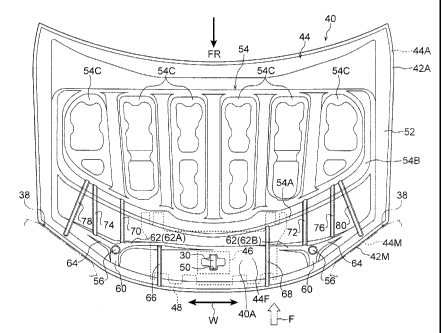
rigidity with respect
to bending loads that act on the front portion of the hood inner panel.
[0004] In consideration of the circumstances described above, an object of
the present
invention is to provide a hood structure for a vehicle that may reduce the
weight of a hood
while assuring rigidity with respect to a bending load that acts on a front
portion of a hood
inner panel.
Solution to Problem
[0005] A hood structure for a vehicle according to a first aspect of the
present invention
includes: a longitudinal bead that is formed at each of left and right sides
of a front portion of
a hood inner panel that structures a hood inner plate, each longitudinal bead
extending in a
hood front and rear direction; and a diagonal bead that is formed at each of
the left and right
sides of the front portion of the hood inner panel, each diagonal bead being
provided at a hood
width direction outer side relative to the corresponding longitudinal bead,
being angled to the
hood width direction outer side toward the hood forward side, and extending
toward a
headlamp portion side in a hood closed state.
[0006] According to the hood structure for a vehicle of the first aspect of
the present
invention, the longitudinal beads that extend in the hood front and rear
direction and the
diagonal beads that are angled to the hood width direction outer sides toward
the hood
1
CA 02896584 2015-07-07
forward side are formed at both the left and right sides of the front portion
(a region at the
hood forward side) of the hood inner panel. In consequence, for example, when
a load acts
on the front portion of the hood inner panel from the hood forward side,
bending deformation
of the front portion of the hood inner panel is suppressed by the longitudinal
beads and
diagonal beads bracing against the load.
[0007] As a further example, when a load acts on the front portion of the
hood inner panel
from the hood upper side, bending deformation of the front portion of the hood
inner panel is
suppressed by the longitudinal beads and diagonal beads bracing against the
load. Because
each diagonal bead is provided at the hood width direction outer side relative
to the
longitudinal bead and extends toward the headlamp portion side in the hood
closed state,
when the load acts from the hood upper side, a portion of the load that is
transmitted to the
diagonal bead is partially borne by the headlamp portion. Thus, bending
deformation of the
front portion of the hood inner panel is effectively suppressed.
[0008] In a hood structure for a vehicle according to a second aspect of
the present
invention, in the first aspect of the present invention, each diagonal bead
does not cross the
corresponding longitudinal bead.
[0009] According to the hood structure for a vehicle of the second aspect
of the present
invention, because each diagonal bead does not cross the longitudinal bead,
when a bending
load acts on the front portion of the hood inner panel, loads that are
transmitted by the
diagonal bead and the longitudinal bead are dispersed in plural directions
rather than being
combined.
[0010] In a hood structure for a vehicle according to a third aspect of the
present
invention, in the first or second aspect of the present invention, an outer
periphery bead is
formed along an outer periphery portion of the hood inner panel, and a hood
forward side end
portion of each diagonal bead connects with the outer periphery bead.
[0011] According to the hood structure for a vehicle of the third aspect of
the present
invention, because the outer periphery bead is formed along the outer
periphery portion of the
hood inner panel, torsional rigidity of the hood inner panel is improved and
operability when
the hood is being opened or closed is excellent. Further, because the end
portion at the hood
forward side of each diagonal bead connects with the outer periphery bead, a
portion of a load
that is transmitted to the diagonal bead is partially borne by the outer
periphery bead.
[0012] In a hood structure for a vehicle according to a fourth aspect of
the present
invention, in the first or second aspect of the present invention, a framework
portion is formed
at a central region of the hood inner panel, and a hood rearward side end
portion of each
diagonal bead connects with the framework portion.
2
CA 02896584 2015-07-07
[0013] According to the hood structure for a vehicle of the fourth aspect
of the present
invention, because the framework portion is formed at the central region of
the hood inner
panel and the end portion at the hood rearward side of each diagonal bead
connects with the
framework portion, a portion of a load that is transmitted to the diagonal
bead is partially
borne by the framework portion.
Advantageous Effects of Invention
[0014] As described hereabove, according to the hood structure for a
vehicle in
accordance with the first aspect of the present invention, an excellent effect
is provided in that
the hood may be reduced in weight while rigidity with respect to a bending
load acting on the
front portion of the hood inner panel may be assured.
[0015] According to the hood structure for a vehicle in accordance with the
second aspect
of the present invention, an excellent effect is provided in that, when a
bending load acts on
the front portion of the hood inner panel, the load may be effectively
dispersed.
[0016] According to the hood structure for a vehicle in accordance with the
third aspect
of the present invention, an excellent effect is provided in that, when a
bending load acts on
the front portion of the hood inner panel, a portion of the load that is
transmitted to a diagonal
bead may be partially borne by the outer periphery bead, and thus local
deformation at a front
end side vicinity of the diagonal bead may be effectively suppressed.
[0017] According to the hood structure for a vehicle in accordance with the
fourth aspect
of the present invention, an excellent effect is provided in that, when a
bending load acts on
the front portion of the hood inner panel, a portion of the load that is
transmitted to a diagonal
bead may be partially borne by the framework portion, and thus local
deformation at a rear
end side vicinity of the diagonal bead may be effectively suppressed.
BRIEF DESCRIPTION OF DRAWINGS
[0018] Fig. 1 is a perspective view showing a vehicle front portion
equipped with a hood
that employs a hood structure for a vehicle in accordance with an exemplary
embodiment of
the present invention.
Fig. 2 is a bottom view showing the hood of Fig. 1 in a state in which the
hood is
viewed from a lower face side.
Fig. 3 is a side view showing a state in which the vehicle of Fig. 1 has had a
frontal
collision.
Fig. 4A shows attached states of a hood left end in a graph comparing attached
states of
the hood structure for a vehicle in accordance with the exemplary embodiment
of the present
invention and of a comparative structure.
3
CA 02896584 2015-07-07
Fig. 4B shows attached states of a hood right end in a graph comparing
attached states
of the hood structure for a vehicle in accordance with the exemplary
embodiment of the
present invention and of the comparative structure.
Fig. 5 is a graph showing relationships between acceleration and displacement
when a
collision object is colliding with a hood front portion.
DESCRIPTION OF EMBODIMENTS
[0019] Structure of an Exemplary Embodiment: A hood structure for a vehicle
according
to an exemplary embodiment of the present invention is described using Fig. 1
to Fig. 5. An
arrow FR that is shown as appropriate in these drawings indicates a vehicle
forward side, an
arrow UP indicates a vehicle upper side, and an arrow W indicates a vehicle
width direction.
In a hood closed state, a hood forward side is in the same direction as the
vehicle forward side
and a hood upper side is in the same direction as the vehicle upper side.
[0020] Fig. 1 shows a perspective view of a vehicle front portion 12 of an
automobile (a
vehicle) 10. As shown in Fig. 1, apron upper members 14 are disposed along the
vehicle
body front and rear direction at upper portions at the two vehicle width
direction end sides of
the vehicle front portion 12. Front end portions of the apron upper members 14
are joined to
rear end portions of radiator support upper sides 18. Each radiator support
upper side 18
extends from the rear end portion thereof to the vehicle forward side,
diagonally toward the
vehicle width direction inner side.
[0021] Front end portions of the radiator support upper sides 18 are joined
to two vehicle
width direction end portions of a radiator support upper 20. The radiator
support upper 20 is
disposed at an upper portion of the vehicle body front end side, with a
longitudinal direction
of the radiator support upper 20 being in the vehicle width direction. The
radiator support
upper 20 supports an upper portion of a radiator (not shown in the drawings).
A radiator
support 16 that is equipped with the radiator support upper sides 18 and the
radiator support
upper 20 is structured in a substantially rectangular frame shape in a front
view, but is not
shown in the drawings. Rubber stoppers 24 for shock absorption are attached to
upper
portions of the two vehicle width direction end sides of the radiator support
upper 20.
[0022] The apron upper members 14, the radiator support upper sides 18 and
the radiator
support upper 20 are disposed inside an engine compartment 22. The engine
compartment
22 is openably and closeably covered by a hood 40 (an engine hood, which is a
component
that can be broadly understood as an "opening and closing body"). In
descriptions of the
hood 40 and portions thereof, a hood forward side end portion is simply
referred to as "the
front end portion" and a hood rear side end portion is simply referred to as
"the rear end
4
CA 02896584 2015-07-07
portion". The hood 40 is attached to the apron upper members 14 via hinges
(not shown in
the drawings) disposed at the rear end portion. The hood 40 moves to turn
about hinge axes
of the hinges, which are in the vehicle width direction, and may open and
close the engine
compartment 22 (i.e., an aperture portion 22A in a vehicle body front
portion). In the closed
state of the hood 40, the apron upper members 14, the radiator support upper
sides 18 and the
radiator support upper 20 are disposed at the vehicle lower side of the hood
40.
100231 Fender panels 32 (also referred to as "front fender panels") are
disposed sideward
of the hood 40, that is, at side faces of the vehicle front portion 12.
Boundaries between the
hood 40 and the :fender panels 32 are corner portions 34. The corner portions
34 extend
substantially in the vehicle front and rear direction at the two vehicle width
direction end
portions of the hood 40. Each fender panel 32 covers the upper side of a front
wheel 36 and
is provided with an outer side vertical wall portion 32A that structures a
design surface. A
cutaway portion 32X is formed at a front end upper portion of each outer side
vertical wall
portion 32A. The cutaway portion 32X is cut away so as to be hollowed in a
recess shape
from the vehicle forward side thereof. A headlamp portion 38 is provided
adjacent to the
cutaway portion 32X.
[0024] The headlamp portion 38 is for illumination forward of the vehicle,
and is
provided with a high-rigidity housing (not shown in the drawings) that
accommodates a light
source (not shown in the drawings). A lamp lens 38A is disposed at an aperture
portion at
the vehicle forward side of the housing. The lamp lens 38A structures a design
surface of
the vehicle and is formed of a transparent, hard material. Thus, the headlamp
portion 38 is
provided with high rigidity.
[0025] The hood 40 is provided with a hood outer panel 42 that structures
an outer plate
of the hood 40 (an outer side portion, which is an upper portion in the closed
state). The
hood 40 is also provided with a hood inner panel 44 (see Fig. 2) that is
disposed at the hood
lower side relative to the hood outer panel 42 and that structures an inner
plate of the hood 40
(an inner side portion, which is a lower portion in the closed state). Fig. 2
shows the hood
40 provided with the hood inner panel 44 in a bottom view (a view in a state
in which the
hood 40 is seen from the hood lower side). An outer periphery edge portion 42A
of the hood
outer panel 42, which is shown in Fig. 1, and an outer periphery edge portion
44A of the hood
inner panel 44, which is shown in Fig. 2, are joined to one another by
hemming. In the state
in which the hood outer panel 42 shown in Fig. 1 and the hood inner panel 44
shown in Fig. 2
have been assembled, the two panels form a closed cross section structure; a
space is formed
in the hood upper and lower direction between the two panels.
[0026] in the bottom view, a hood width direction central portion of a
:front end edge
CA 02896584 2015-07-07
portion 44M of the hood inner panel 44 bulges to the hood forward side
relative to the two
hood width direction side portions of the front end edge portion 44M.
Similarly, in the
bottom view, a hood width direction central portion of a front end edge
portion 42M of the
hood outer panel 42 shown in Fig. 1 bulges to the hood forward side relative
to the two hood
width direction side portions of the front end edge portion 42M. The two hood
width
direction side portions of the front end edge portion 42M of the hood outer
panel 42 are
disposed adjacent to the upper sides of upper edge portions of the
aforementioned lamp lenses
38A.
[0027] A hood lock portion 26 is disposed in correspondence with a hood
width direction
central portion of a front end portion 40A of the hood 40 in the closed state.
The hood lock
portion 26 includes a hood lock device 28 (which is shown as a block in the
drawings) and a
striker 30. The hood lock device 28 is disposed at the radiator support upper
20, inside the
engine compartment 22. The striker 30 is disposed at the hood 40. The striker
30 is
formed in an inflected shape of which the hood upper side is open in a vehicle
side view (a
substantial "U" shape). A latch (not shown in the drawings) that structures a
portion of the
hood lock device 28 is engageable with the striker 30. In the state in which
the latch is
engaged with the striker 30, the front end portion 40A of the hood 40 is
pulled down to the
hood lower side.
[0028] As shown in Fig. 2, a penetrating hole 50 is formed penetrating
through a central
portion of a front portion 44F of the hood inner panel 44 (a region (a front
portion region) at
the hood forward side relative to a framework portion 54, which is described
below). The
penetrating hole 50 is for insertion of the striker 30 from the hood upper
side thereof A pair
of front and rear mounting base end portions of the striker 30 are bent to one
side and another
side in the vehicle width direction (not shown in the drawings) and the
striker 30 is fixed to a
baseplate 46 at the hood upper side of the hood inner panel 44. The baseplate
46 is fixed to a
hood lock reinforcement 48 (which is a component that can be broadly
understood as a
"reinforcing member").
[0029] The hood lock reinforcement 48 is formed in a plate shape. The hood
lock
reinforcement 48 is disposed between the hood outer panel 42 (see Fig. 1) and
the hood inner
panel 44 for reinforcement of a hood width direction central portion of the
front end portion
40A of the hood 40. A penetrating hole (not shown in the drawings) that
corresponds with
the penetrating hole 50 of the hood inner panel 44 is formed penetrating
through the hood
lock reinforcement 48. The hood lock reinforcement 48 is welded to the hood
inner panel 44
at portions surrounding the penetrating hole 50. Thus, the hood lock
reinforcement 48
reinforces the hood 40 in the vicinity of a striker mounting portion.
6
CA 02896584 2015-07-07
[0030] An outer periphery bead 52 is formed along an outer periphery
portion of the hood
inner panel 44 that structures the inner face of the hood 40. The outer
periphery bead 52 is
formed in a shape that protrudes to the hood lower side. The outer periphery
bead 52 runs
around the outer periphery portion of the hood inner panel 44, and the
framework portion 54
is formed at a central region of the hood inner panel 44.
[0031] The framework portion 54 is provided at the hood inner panel 44, at
the inner side
of the outer periphery bead 52 and at the hood rearward side relative to the
mounting portion
of the striker 30. In the present exemplary embodiment, the framework portion
54 is
specified to be disposed mainly at the hood upper side relative to surrounding
portions. A
front wall portion 54A is formed at a front end portion of the framework
portion 54. The
front wall portion 54A stands toward the hood upper side. A flat portion 54B
is also formed
at the framework portion 54, at the hood rearward side of the front wall
portion 54A, in a
substantial "U" shape in the hood bottom view. The flat portion 54B is
provided with a
general surface thereof being a surface that includes the hood width direction
as a surface
direction. Plural projection portions 54C are also formed at the framework
portion 54. The
projection portions 54C are formed at the inner side of the flat portion 54B,
in substantial "U"
shapes in the hood bottom view. The projection portions 54C are provided in
order to raise
the rigidity of central regions of the hood inner panel 44. The projection
portions 54C are
formed so as to form shapes that protrude to the hood upper side, and are
arranged side by
side in the hood width direction with predetermined spacings therebetween.
Aperture
portions are formed in top portions of the projection portions 54C, in order
to reduce weight.
Portions of the top portions of the projection portions 54C are joined to a
rear face of the hood
outer panel 42 (see Fig. 1) via an adhesive (a mastic).
[0032] Stopper abutting portions 56 are formed at both left and right sides
in the hood
width direction of the front portion 44F of the hood inner panel 44, at the
hood forward side
relative to the framework portion 54. The stopper abutting portions 56 are
specified to be
disposed to abut against the rubber stoppers 24 mentioned above (see Fig. 1)
in the closed
state of the hood 40. Consequently, when the hood 40 is closed, the rubber
stoppers 24
shown in Fig. 1 are interposed between the stopper abutting portions 56 of the
hood 40 (see
Fig. 2) and the radiator support upper 20.
[0033] As shown in Fig. 2, reinforcing protrusion portions 60, 62 and 64
are formed at
the hood inner panel 44, extending in plural directions (three directions in
the present
exemplary embodiment) from each stopper abutting portion 56. The reinforcing
protrusion
portions 60, 62 and 64 are all formed so as to form shapes that protrude to
the hood upper side.
The plural (threes in the present exemplary embodiment) reinforcing protrusion
portions 60,
7
CA 02896584 2015-07-07
62 and 64 are all specified to not be arranged in line with one another along
straight lines. In
the present exemplary embodiment, the reinforcing protrusion portions 60, 62
and 64 at the
vehicle left side and the reinforcing protrusion portions 60, 62 and 64 at the
vehicle right side
are specified to have general left¨right symmetry. The reinforcing protrusion
portions with
symmetric relationships are assigned the same reference numerals.
[0034] Each first reinforcing protrusion portion 60, which is one of the
plural reinforcing
protrusion portions 60, 62 and 64, extends to the hood forward side from the
stopper abutting
portion 56 and connects with the outer periphery bead 52. In contrast, the
other two of the
reinforcing protrusion portions 60, 62 and 64, the second reinforcing
protrusion portion 62
and the third reinforcing protrusion portion 64, are not connected with the
outer periphery
bead 52. The second reinforcing protrusion portion 62 extends to the hood
width direction
inner side from the stopper abutting portion 56. The left side second
reinforcing protrusion
portion 62 (62A) extends as far as a hood width direction central portion,
which is a region at
which the hood inner panel 44 overlaps with the hood lock reinforcement 48 in
a hood plan
view. In contrast, the right side second reinforcing protrusion portion 62
(62B) does not
extend to the region at which the hood inner panel 44 overlaps with the hood
lock
reinforcement 48 in the hood plan view. Each third reinforcing protrusion
portion 64
extends diagonally to the hood width direction outer side and the rearward
side from the
stopper abutting portion 56.
[0035] Longitudinal beads 66 and 68 are formed at both the left and right
sides of the
front portion 44F of the hood inner panel 44. The longitudinal beads 66 and 68
are formed
at the two sides of the region that overlaps with the hood lock reinforcement
48 in the hood
plan view. The longitudinal beads 66 and 68 are formed so as to form shapes
that protrude
to the hood upper side, and extend in the hood front and rear direction. Front
end portions of
the longitudinal beads 66 and 68 connect with the outer periphery bead 52. A
rear end
portion of the left side longitudinal bead 66 connects with a front end
portion of the second
reinforcing protrusion portion 62 (62A). A rear end portion of the right side
longitudinal
bead 68 connects with the front wall portion 54A of the framework portion 54.
[0036] Further, longitudinal beads 70 and 72 are formed at both the left
and right sides of
the front portion 44F of the hood inner panel 44, at the hood width direction
outer sides
relative to the longitudinal beads 66 and 68 described above, The longitudinal
beads 70 and
72 are specified to be at the hood width direction outer sides relative to the
region of the hood
inner panel 44 that overlaps with the hood lock reinforcement 48 in the hood
plan view. The
longitudinal beads 70 and 72 are formed so as to form shapes that protrude to
the hood upper
side, and extend in the hood front and rear direction. Front end portions of
the longitudinal
8
CA 02896584 2015-07-07
beads 70 and 72 connect with rear end portions of the second reinforcing
protrusion portions
62 at the hood width direction outer sides of the reinforcing protrusion
portions 62. Rear end
portions of the longitudinal beads 70 and 72 connect with the front wall
portion 54A and flat
portion 54B of the framework portion 54. Thus, the longitudinal beads 70 and
72 link the
second reinforcing protrusion portions 62 with the framework portion 54.
[0037] Further yet, longitudinal beads 74 and 76 are formed at both the
left and right
sides of the front portion 44F of the hood inner panel 44, at the hood width
direction outer
sides relative to the longitudinal beads 70 and 72 described above. The
longitudinal beads
74 and 76 are formed so as to form shapes that protrude to the hood upper
side, and extend in
the hood front and rear direction. Front end portions of the longitudinal
beads 74 and 76
connect with rear end portions of the third reinforcing protrusion portions 64
at the hood
width direction outer sides of the third reinforcing protrusion portions 64.
Rear end portions
of the longitudinal beads 74 and 76 connect with the front wall portion 54A
and flat portion
54B of the framework portion 54. Thus, the longitudinal beads 74 and 76 link
the third
reinforcing protrusion portions 64 with the framework portion 54.
[0038] Diagonal beads 78 and 80 are formed at both the left and right sides
of the front
portion 44F of the hood inner panel 44, at the hood width direction outer
sides relative to the
longitudinal beads 66, 68, 70, 72, 74 and 76. The diagonal beads 78 and 80 are
formed so as
to form shapes that protrude to the hood upper side. The diagonal beads 78 and
80 extend in
directions that are angled to the hood width direction outer sides toward the
hood forward side,
that are oriented toward sides at which the headlamp portions 38 (see Fig. 1)
are disposed in
the hood closed state, and that are roughly orthogonal to the headlamp
portions 38. The
diagonal beads 78 and 80 are formed to not cross the longitudinal beads 66,
68, 70, 72, 74 and
76 and to not cross the reinforcing protrusion portions 60, 62 and 64.
[0039] Front end portions of the diagonal beads 78 and 80 connect with the
outer
periphery bead 52. Rear end portions of the diagonal beads 78 and 80 connect
with the front
wall portion 54A and flat portion 54B of the framework portion 54. Thus, the
diagonal
beads 78 and 80 link the outer periphery bead 52 with the framework portion
54.
[0040] Operation and Effects of the Exemplary Embodiment: Now, operations
and effects
of the above exemplary embodiment are described.
[0041] In the present exemplary embodiment, the longitudinal beads 66, 68,
70, 72, 74
and 76 that extend in the hood front and rear direction and the diagonal beads
78 and 80 that
are angled to the hood width direction outer sides toward the hood forward
side are formed at
both the left and right sides of the front portion 44F of the hood inner panel
44. Therefore,
when a load F acts on the front portion 44F of the hood inner panel 44 from
the hood forward
9
CA 02896584 2015-07-07
side, bending deformation of the front portion 44F of the hood inner panel 44
is suppressed by
the longitudinal beads 66, 68, 70, 72, 74 and 76 and diagonal beads 78 and 80
bracing against
the load.
[0042] In Fig. 3, a state of deformation of the hood 40 when the automobile
10 shown in
Fig. 1 has had a frontal collision is shown in a side view. As shown in Fig.
3, bending
deformation of the front end portion 40A is suppressed and the hood 40 is
subjected to
bending deformation at an intermediate portion 40X in the hood front and rear
direction.
Thus, pushback (movement to the vehicle rearward side) of the rear end portion
of the hood
40 is suppressed. That is, collision performance (damageability performance)
during a
frontal collision of the automobile 10 may be improved even though an increase
in weight of
the hood 40 is moderated.
[0043] Further, for example, if an impacter 90, which is represented by two-
dot chain
lines in Fig. 1, collides with the front portion of the hood 40 diagonally
from the hood
forward-upper side and a load acts on the front portion 44F of the hood inner
panel 44 shown
in Fig. 2, the longitudinal beads 66, 68, 70, 72, 74 and 76 and diagonal beads
78 and 80 brace
against the load. Therefore, bending deformation of the front portion 44F of
the hood inner
panel 44 is suppressed, as a result of which bending deformation of the front
portion of the
hood 40 is suppressed.
[0044] In this structure, the diagonal beads 78 and 80 are provided at the
hood width
direction outer sides relative to the longitudinal beads 66, 68, 70, 72, 74
and 76, and extend
toward the sides at which the headlamp portions 38 are disposed in the closed
state of the
hood 40 (see Fig. 1). Therefore, when a load acts from the hood upper side, a
portion of the
load that is transmitted to either of the diagonal beads 78 and 80 is
partially borne by the
high-rigidity headlamp portion 38 (see Fig. 1). Thus, bending deformation of
the front
portion 44F of the hood inner panel 44 is effectively suppressed.
[0045] In the present exemplary embodiment, the diagonal beads 78 and 80
are formed to
not cross the longitudinal beads 66, 68, 70, 72, 74 and 76. Therefore, when a
bending load
acts on the front portion 44F of the hood inner panel 44, loads that are
transmitted by the
diagonal beads 78 and 80 and the longitudinal beads 66, 68, 70, 72, 74 and 76
do not combine
but are dispersed in plural directions. Therefore, loads can be effectively
dispersed.
[0046] In the present exemplary embodiment, because the outer periphery
bead 52 is
formed along the outer periphery portion of the hood inner panel 44, torsional
rigidity of the
hood inner panel 44 is improved and operability during opening and closing of
the hood 40 is
excellent. Furthermore, because the front end portions of the diagonal beads
78 and 80
connect with the outer periphery bead 52, a portion of a load that is
transmitted to either of the
CA 02896584 2015-07-07
diagonal beads 78 and 80 is partially borne by the outer periphery bead 52.
Therefore, local
deformations in vicinities of the front end sides of the diagonal beads 78 and
80 are
effectively suppressed.
[0047] In the present exemplary embodiment, because the framework portion
54 is
formed at the central region of the hood inner panel 44 and the rear end
portions of the
diagonal beads 78 and 80 connect with the framework portion 54, a portion of a
load that is
transmitted to either of the diagonal beads 78 and 80 is partially borne by
the framework
portion 54. Therefore, local deformations in vicinities of the rear end sides
of the diagonal
beads 78 and 80 are effectively suppressed.
[0048] Now, a supplementary description is given while referring to graphs
in Fig. 4A
and Fig. 4B that show measurement results in an attached state. The term
"attached state"
specifically refers to the state in which the hood front end is pulled down by
the hood lock.
Fig. 4A represents the attached state at the hood left side, and Fig. 4B
represents the attached
state at the hood right side. The vertical axes in these drawings represent
positions in the
vehicle front and rear direction, and the horizontal axes represents offset
amounts in the
vehicle upper and lower direction by reference to a height position of the
hood front end in a
state in which the hood is not locked (a state in which the hood front end is
not pulled down).
[0049] The solid line in each graph shows results for the hood 40 in which
the hood
structure for a vehicle according to the present exemplary embodiment is
employed, and the
dotted line in each graph shows results for a hood in which a comparative
structure is
employed. The comparative structure is a structure in which the longitudinal
beads 66, 68,
70, 72, 74 and 76 and diagonal beads 78 and 80 of the hood structure for a
vehicle according
to the present exemplary embodiment are not formed. The comparative structure
has the
same structure as the hood structure for a vehicle according to the present
exemplary
embodiment in other respects. The two-dot chain lines in each graph show upper
and lower
limits of a preferable range.
[0050] As is shown in Fig. 4A and Fig. 4B, in the hood of the comparative
structure (see
the dotted lines), the front portion locally recesses to the vehicle lower
side at both left and
right. In contrast, in the hood 40 in which the hood structure for a vehicle
according to the
present exemplary embodiment is employed, as shown by the solid lines in the
graphs, local
recessing of the front portion is suppressed at both left and right. Thus,
attachment of the
hood 40 is excellently established.
[0051] To add to these descriptions, if measures are taken to reduce the
weight of the
hood inner panel (the hood)¨simply reducing the plate thickness or changing
the material
from steel to an aluminum alloy, a resin material or the like---a
predetermined rigidity may
11
CA 02896584 2015-07-07
not be assured, as in the comparative structure mentioned above. However, with
the present
exemplary embodiment, a predetermined rigidity is assured even with the same
plate
thickness and the same material as the comparative structure. Therefore,
attachment
performance may be assured even while the hood is reduced in weight and costs
are lowered.
Moreover, because a predetermined rigidity may be assured at both sides of the
front portion
of the hood 40 shown in Fig. 2, including portions surrounding the stopper
abutting portions
56, there is no need to attach separate reinforcing members or enlarge the
hood lock
reinforcement 48 to the hood width direction outer sides thereof. Even if the
weight of
components that are supported by the front portion 44F of the hood inner panel
44 increases,
bending deformation of the front portion 44F of the hood inner panel 44 may be
prevented
even while an increase in overall weight of the hood 40 is suppressed compared
to a case of
reinforcing with a reinforcing member other than the hood inner panel 44.
[0052] Now, a supplementary description is given of operation in relation
to pedestrian
protection performance using Fig. 5, which shows an acceleration¨displacement
characteristic
(G-S characteristic). Fig. 5 shows acceleration--displacement curves (G-S
curves; pedestrian
protection test results), which illustrate relationships between acceleration
(front¨rear G,
which is negative acceleration but is shown by absolute values in Fig. 5) and
displacement
amounts (S) when a collision body (an impacter) collides with a front end side
portion of the
hood diagonally from the vehicle upper-forward side. The solid line shown in
Fig. 5
illustrates the acceleration¨displacement characteristic when the hood
structure for a vehicle
according to the present exemplary embodiment is employed, and the two-dot
chain line
illustrates the acceleration¨displacement characteristic when a hood structure
for a vehicle
according to a comparative structure is employed. The comparative structure is
a structure
in which the longitudinal beads 66, 68, 70, 72, 74 and 76 and diagonal beads
78 and 80 of the
hood structure for a vehicle according to the present exemplary embodiment are
not formed.
As can be seen from the graphs in Fig. 5, when the hood structure for a
vehicle according to
the present exemplary embodiment is employed, the values of acceleration in
the initial stage
of the collision (front¨rear G) are higher and the values of acceleration
(front¨rear G) in the
final phase of the collision are correspondingly suppressed. Thus, excellent
energy
absorption (EA) is realized. That is, pedestrian protection performance is
improved.
[0053] As described above, according to the hood structure for a vehicle in
accordance
with the present exemplary embodiment, the hood 40 as shown in Fig. 2 and such
may be
reduced in weight while rigidity with respect to a bending load acting on the
front portion 44F
of the hood inner panel 44 may be assured.
[0054] Supplementary Descriptions of the Embodiments: The number of the
longitudinal
12
CA 02896584 2015-07-07
beads formed at the hood inner panel may be set to a different number from the
exemplary
embodiment described above.
[0055] As a variant example of the exemplary embodiment described above, a
structure
may be employed in which diagonal beads that cross the longitudinal beads are
formed at the
hood inner panel. As a further variant example of the above exemplary
embodiment, a
structure may be employed in which the front end portions of the diagonal
beads do not
connect with the outer periphery bead. As a yet further variant example of the
above
exemplary embodiment, a structure may be employed in which the rear end
portions of the
diagonal beads do not connect with the framework portion.
[0056[ The exemplary embodiment described above and the numerous variant
examples
mentioned above may be embodied in suitable combinations.
[0057] Hereabove, an example of the present invention has been described.
The present
invention is not limited by these descriptions, and it will be clear that
numerous modifications
outside of these descriptions may be embodied within a technical scope not
deviating from the
gist of the invention.
13