Note: Descriptions are shown in the official language in which they were submitted.
CA 2896664 2017-02-28
ELECTRICAL POWER COUPLING WITH MAGNETIC CONNECTIONS
FIELD OF THE INVENTION
[0001] The present invention relates to electrical power and/or electronic
data outlets,
receptacles, and connectors for establishing establish direct electrical
connections between
respective electrical conductors.
BACKGROUND OF THE INVENTION
(0002) Many different types of electrical and electronic data connectors have
been devised for
transmitting electrical power or electrical signals from one or more
electrical conductors to
another one or more electrical conductors. For example, male to female
electrical connections
are commonly used to establish proper connections for compatible conductors,
whether for
power or data signal transmission.
[0003) While connectors are frequently provided at the ends of respective
flexible cords, in some
applications such as work area environments it is desirable to rigidly or semi-
rigidly mount
connectors to another object or surface, such as an article of furniture or a
wall or floor surface.
However, rigidly or semi-rigidly mounted connectors present challenges such as
proper
alignment of one connector with another connector.
SUMMARY OF THE INVENTION
[00041 The present invention provides an electrical power coupling that
utilizes magnetic
connections and movable coupler parts to establish and maintain electrical
contact between
power transmitter that is mountable on a wall surface, furniture article, or
the like, and a power
receiver mountable that is mountable on another surface or article. Typically
one or both of the
transmitter and the receiver has a movable coupling portion mounted to a
respective base, and
may further include a magnetic or magnetically permeable material to help
align and maintain a
proper connection between the respective coupling portions. The power coupling
permits power
transfer, such as low voltage DC power transfer, via a magnet coupling that
incorporates
moveable components to facilitate and permit a proper electrical connection
even when there are
misalignments between the power transmitter and the power receiver.
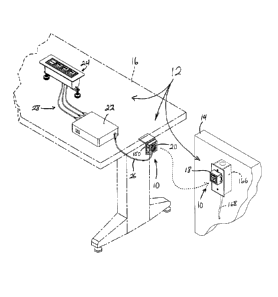
1
CA 02896664 2015-07-09
[0005] According to one form of the invention, an electrical power coupling
includes a pair of
power coupling parts each having a base and a coupling portion, with first and
second electrical
contacts and a magnetic element at each coupling portion. The bases of the
power coupling parts
are configured for mounting to respective surfaces, and the coupling portions
are each movable
relative to the respective bases. The first electrical contacts are spaced
laterally outboard a first
distance from a center of each of the coupling portions, and the second
electrical contacts are
spaced a second distance laterally outboard from the center of each of the
coupling portions,
where the second distance is greater than the first distance. The magnetic
elements are attracted
to one another when the coupling portions are positioned in close proximity to
one another so
that the coupling portions will move relative to their respective bases, and
so that the coupling
portions substantially align with one another to establish electrical
connections between the first
electrical contacts and between the second electrical contacts upon
positioning the coupling
portions in close proximity.
100061 In one aspect, a first of the power coupling parts is an electrical
power transmitter and a
second of the power coupling parts is an electrical power receiver.
Optionally, the first electrical
contact of the electrical power transmitter includes an outwardly-biased
contact pin, and the first
electrical contact of the electrical power receiver includes a circular
conductive surface. Further
optionally, the second electrical contact of the electrical power transmitter
is in the form of an
outwardly-biased contact pin, and the second electrical contact of the
electrical power receiver is
in the form of a circular conductive surface.
100071 In another aspect, the first electrical contact of the electrical power
transmitter includes a
plurality of the outwardly-biased contact pins that are spaced
circumferentially apart from one
another and are equidistant from the center, while the second electrical
contact of the electrical
power transmitter includes a plurality of the outwardly-biased contact pins
that are paced
circumferentially apart from one another and are equidistant from the center.
[0008] In yet another aspect, the coupling portion of a first of the power
coupling parts is
pivotable about at least two pivot axes relative to the base of the first of
the power coupling
parts. Optionally, the coupling portion of the first of the power coupling
parts is pivotably
coupled to the base of the first of the power coupling parts via pivot pins.
[0009] In a further aspect, the coupling portion of a second of the power
coupling parts is
longitudinally extendable along a longitudinal axis extending through the
center of the second of
-2-
CA 02896664 2015-07-09
the power coupling parts. Optionally, the two pivot axes of the first power
coupling part are
orthogonal to one another, and the longitudinal axis of the second power
coupling part is
orthogonal to the two pivot axes of the first power coupling part.
100101 In still another aspect, each of the power coupling parts further
includes a biasing
member that is configured to move or retain a respective one of the coupling
portions to a
retracted position relative to a respective one of the bases when the coupling
portions are
disengaged from one another. Optionally, the biasing member is at least one
chosen from a
magnet and a spring.
[0011] In a still further aspect, the magnetic element of a first of the
coupling portions includes a
permanent magnet, and the magnetic element of a second of the coupling
portions includes at
least one chose from a permanent magnet and a magnetically permeable material.
[0012] According to another form of the invention, an electrical power
coupling includes a
power transmitter, a power receiver, and at least four electrical contacts.
The power transmitter
has a transmitter base configured for mounting to a first surface, and further
includes a power
transmission portion coupled to the transmitter base. The power receiver has a
receiver base that
is configured for mounting to a second surface, and further includes a power
receiver portion
couple to the receiver base. The electrical contacts include at least two
power transmission
contacts at the power transmission portion, and at least two power receiver
contacts at the power
receiver portion. The power receiver contacts are configured to electrically
engage respective
ones of the at least two power transmission contacts. At least two of the
electrical contacts are
arcuate or circular in shape and have respective radii of curvature
corresponding to a respective
radial distance of each of the arcuate or circular electrical contacts to a
center of a respective one
of the power transmission portion or the power receiver portion. At least two
others of the
electrical contacts are (i) configured and positioned to engage respective
ones of the arcuately
shaped electrical contacts, and (ii) selectively positionable at different
discrete locations that are
spaced circumferentially apart along the respective ones of the arcuately
shaped electrical
contacts when the power receiver is rotated relative to the power transmitter.
[0013] Optionally, the arcuately shaped electrical contacts are fully circular
in shape.
[0014] In one aspect, the power transmission portion is movable relative to
the transmitter base
and the power receiver portion is movable relative to the power receiver
portion. Optionally, the
-3-
CA 02896664 2015-07-09
power transmission portion is one of pivotably coupled to the power
transmitter base, and the
power receiver portion is translatably coupled to the power receiver base.
100151 In another aspect, the electrical power coupling further includes a
magnetic element in
each of the power transmission portion and the power receiver portion, in
which the magnetic
elements are configured to attract one another to thereby facilitate
establishing direct electrical
connections between the power transmission contacts and respective ones of the
power
transmission contacts.
100161 In a further aspect, at least two others of the electrical contacts
include a first pair of
outwardly-biased contact pins that are radially aligned with one another and a
second pair of
outwardly-biased contact pins that are radially-aligned with one another and
spaced
circumferentially apart from respective ones of the first pair of the
outwardly-biased contact pins.
100171 In still another aspect, a first of the at least two power transmission
contacts is spaced
laterally outboard by a first distance from a center of the power transmission
portion, and a first
of the at least two power receiver contacts is spaced laterally outboard by
the first distance from
a center of the power receiver portion. Optionally, a second of the at least
two power
transmission contacts is spaced laterally outboard by a second distance from
the center of the
power transmission portion, and a second of the at least two power receiver
contacts is spaced
laterally outboard by the second distance from the center of the power
receiver portion, and in
which the second distance is greater than the first distance.
100181 In yet another aspect, a magnetic element is positioned at the center
of each of the power
transmission portion and the power receiver portion. The magnetic elements are
configured to
attract one another to thereby facilitate establishing direct electrical
connections between the at
least two power transmission contacts and respective ones of the at least two
power transmission
contacts.
100191 Thus, the electrical power coupling of the present invention permits
low voltage power
transfer via a coupling that incorporates moveable components, and typically
magnetic
attraction, to facilitate a proper electrical connection even in the event of
misalignments between
the power transmitter and the power receiver. The device may be adapted for
use in high voltage
power arrangements and may also be adapted for wireless conductive charging or
power transfer,
for example.
100201
-4-
CA 02896664 2015-07-09
100211 These and other objects, advantages, purposes and features of the
present invention will
become apparent upon review of the following specification in conjunction with
the drawings.
BRIEF DESCRIPTION OF THE DRAWINGS
[0022] FIG. 1 is a perspective view of an electrical power system and coupling
with magnetic
connections in accordance with the present invention;
[0023] FIG. 2 is a side elevation of a power transmitter mounted along a wall
surface and a
power receiver mounted along a table, depicting initial magnetic interaction;
[0024] FIG. 3 is a side elevation of the power transmitter and power receiver
of FIG. 2, shown in
a coupled configuration;
[0025] FIGS. 4-6 are perspective views of the power transmitter and power
receiver in spaced
arrangement prior to coupling;
[0026] FIG. 7 is a front elevation of inner portions of the power transmitter
with side portions
partially cut away to show internal structure;
100271 FIG. 8 is another front elevation of another power transmitter of FIG.
7;
100281 FIG. 9 is a side sectional elevation taken along line IX-IX in FIG. 8,
with the transmitter
base housing removed for clarity;
[0029] FIG. 10 is a side sectional elevation taken along line X-X in FIG. 8,
with the transmitter
base housing removed for clarity;
[0030] FIG. 11 is another front elevation of the power transmitter;
[0031] FIGS. 12A and 12B are side sectional elevations taken along line XII-
XII of FIG. 11 and
depicting different pivoted positions of the power transmitter coupling
portion relative to its
base;
100321 FIGS. 13A and 13B are side sectional elevations taken along line XIII-
XIII of FIG. 11
and depicting different pivoted positions of the power transmitter coupling
portion relative to its
base;
100331 FIG. 14 is a front elevation of the power transmitter;
100341 FIGS. 15A and 15B are side sectional elevations taken along line XV-XV
of FIG. 14 and
depicting retracted and extended positions of the power receiver's coupling
portion relative to its
base;
[0035] FIG. 16 is an elevation view of a power receiver and power transmitter
shown coupled
together;
-5-
CA 02896664 2015-07-09
100361 FIG. 17 is a side sectional elevation of the coupled power receiver and
power transmitter
taken along line XVII-XVII of FIG. 16;
100371 FIG. 18 is another elevation view of a power receiver and power
transmitter;
[0038] FIG. 19A is a side sectional elevation of the power receiver and power
transmitter taken
along line XIX of FIG. 18, shown just prior to coupling and including an
enlarged view of an
electrical coupling region;
[0039] FIGS. 19B is another side sectional elevation of the power receiver and
power transmitter
taken along line XIX of FIG. 18, shown in the coupled configuration and
including an enlarged
view of an electrical coupling region;
[0040] FIG. 20 is an exploded perspective view of the power receiver, in which
pivoting housing
portions are omitted;
100411 FIG. 21 is an exploded perspective view of the power transmitter, in
which certain
housing portions are omitted;
100421 FIG. 22 is an enlarged exploded perspective view of a rear portion of
the power receiver;
[0043] FIG. 23 is a front elevation of another power transmitter in accordance
with the present
invention;
[0044] FIG. 24 is a side sectional elevation of the power transmitter taken
along line XIV-XIV
of FIG. 23;
100451 FIGS. 24A and 24B are additional side sectional elevations of the power
transmitter of
FIG. 23, depicting different pivoted positions of the power transmitter
coupling portion relative
to the power transmitter base;
[00461 FIG. 25 is a perspective view of a table incorporating an electrical
system with power
transmitter and power receiver, onboard power supply, and low voltage outlets,
including
enlarged views of an alternative low voltage power unit and of various
different power level
indicators; and
100471 FIGS. 26-28 are perspective views of the power transmitter in different
mounting and
power supply configurations.
DESCRIPTION OF THE PREFERRED EMBODIMENTS
[0048] Referring now to the drawings and the illustrative embodiments depicted
therein, an
electrical power coupling 10 is incorporated into an electrical power system
12, which is
mountable along various surfaces such as a wall surface 14 and a furniture
article 16, such as
-6-
CA 02896664 2015-07-09
shown in FIG. 1. Electrical power coupling 10 includes a power transmitter 18
and a power
receiver 20, each having a respective power coupling part arranged so that the
power coupling
parts are configured to engage one another and thereby establish a direct
electrical connection
between power transmitter 18 and power receiver 20, even in the event that the
power transmitter
18 and power receiver 20 are misaligned with one another and/or are at
different rotational
positions relative to one another.
[0049] In the illustrated embodiment of FIG. 1, electrical power system 12
further includes an
electrical power storage unit such as a battery 22, and an electrical
receptacle unit 24, which are
both mounted to furniture article 16 such as a work table or the like. An
electrical wire 26
couples power receiver 20 to battery 22, and additional electrical wires 28
coupled battery 22 to
electrical receptacle unit 24. As will be described in more detail below,
power transmitter 18 and
power receiver 20 of electrical power coupling 10 include respective coupling
portions that are
configured to move into proper alignment and engagement with one another when
furniture
article 16 is positioned and aligned with power receiver 20 located
sufficiently close to power
transmitter 18, such as shown in FIGS. 2 and 3.
[0050] Electrical power transmitter 18 includes a transmitter base or housing
30 and a power
transmission portion or coupling 32 that is movably coupled to transmitter
base 30, such as
shown in FIGS. 4-13B. Transmitter base 30 includes a plurality of sidewalls
34, a forward
surface 36 defining an opening 38 through which transmission portion 32 is
accessible, and a
back panel 40 located opposite forward surface 36 and enclosing a rear portion
of power
transmitter 18 (FIGS. 4-6). Similarly, electrical power receiver 20 includes a
receiver base or
housing 42 and a power receiver portion or coupling 44 that is movably coupled
to receiver base
42. Receiver base 42 includes a plurality of sidewalls 46, a forward surface
48 defining an
opening 50 through which receiver portion 44 is accessible, and a back panel
52 located opposite
forward surface 48 and enclosing a rear portion of power receiver 20.
[0051] Power transmission portion or coupling 32 is assembled from a multi-
piece power
transmission housing 54 containing a permanent magnet 56 at its center, and a
plurality of
electrical contacts in the form of outwardly or forwardly-biased pins 58, as
shown in FIGS. 6-10,
19A, 19B, and 21, and in particular FIGS. 9 and 10. Power transmission housing
54 includes an
outer housing piece 60, an intermediate housing piece 62, and an inner housing
assembly 64 that
supports magnet 56 and contact pins 58. Inner housing assembly 64 includes an
outer perimeter
-7-
CA 02896664 2015-07-09
piece 64a, an inner perimeter piece 64b, a backing piece 64c, a central and
forward housing piece
64d, a magnet-backing piece 64e, a pin-backing piece 64f, and a central magnet
holder 64g, such
as shown in FIGS. 9, 10, and 21.
100521 Outer housing piece 60 is sized and shaped to be received within a
cavity or inner
chamber defined by transmitter base 30, such that outer housing piece 60
remains substantially
fixed relative to transmitter base 30. Intermediate housing piece 62 includes
a pair of outwardly-
extending pivot pins 66 that engage respective bores defined along interior
surfaces of opposite
sidewalls of the outer housing piece 60, such as shown in FIGS. 7 and 10. A
space 68 is defined
between respective rear panels of intermediate housing piece 62 and outer
housing piece 60, and
permits intermediate housing piece 62 to pivot by a limited amount or degree
about a first pivot
axis 70, such as shown in FIGS. 10, 12A, and 12B. Similarly, power
transmission housing 54
(specifically, outer perimeter piece 64a) includes a pair of outwardly-
extending pivot pins 72 on
opposite sides thereof, for engaging respective bores defined along interior
surfaces of opposite
sidewalls of the intermediate housing piece 62, such as shown in FIGS. 7 and
9. A space 74 is
defined between backing piece 64c and a rear panel of intermediate housing
piece 62, which
permits power transmission housing 54 to pivot by a limited amount or degree
about a second
pivot axis 76, such as shown in FIGS. 9, 13A, and 13B. Thus, pivot pins 66, 72
permit power
transmission housing 54 to pivot about two different axes 70, 76 relative to
outer housing piece
60 and power transmitter base 30 in a gimballing or gimbal-like manner, where
pivot axes 70, 76
are substantially perpendicular or orthogonal to one another and lie in
respective lateral planes.
100531 Magnet-backing piece 64e is secured to central and forward housing
piece 64d by a
plurality of threaded fasteners 78, such as shown in FIGS. 9, 10, and 17. A
space or cavity is
defined between magnet-backing piece 64e and the central and forward housing
piece 64d, and is
sized and shaped to secure pin-backing piece 64f and central magnet holder
64g, where the pin-
backing piece 64f engages a radial flange 80 of central magnet holder 64g to
secure the central
magnet holder 64g and magnet 56 relative to central and forward housing piece
64d and magnet-
backing piece 64e. A plurality of biasing members in the form of coil springs
81 are held in
compression between the central and forward housing piece 64d and the pin-
backing piece 64f,
and are disposed in or behind respective contact pins 58 (FIG. 19A) so that
the springs bias the
pins 58 forwardly and out through respective openings 82 defined in an annular
forward surface
84 of the central and forward housing piece 64d, such as shown in FIG. 21. Pin-
backing piece
-8-
CA 02896664 2015-07-09
64f defines respective bores 86 with which contact pins 58 are aligned, so
that individual
conductors (not shown) that are associated with the contact pins 58 may pass
through pin-
backing piece 64f to establish electrical connections with respective
terminals of an electrical
coupling piece 88 that is mounted in one of the sidewalls 34 of transmitter
base 30, such as
shown in FIGS. 4, 6, and 21. Referring to FIG. 21, it is readily seen that
each of central and
forward housing piece 64d, magnet-backing piece 64e, pin-backing piece 64f,
and magnet holder
64g defines a respective bore or opening for receiving magnet 56 and/or magnet
holder 64g.
[0054] Contact pins 58 are arranged in two sets of three, including an
innermost set of three pins
58a having a first polarity or electrical potential, and an outermost set of
three pins 58b having a
second or opposite polarity or electrical potential. The innermost pins 58a
are set a first radial
distance (i.e., are equidistant) from a center or central axis 90 that passes
through the middle of
annular forward surface 84 and magnet 56, and are circumferentially evenly
spaced apart from
one another, with 120 degrees of separation between each of the three
innermost pins 58a.
Similarly, the outermost pins 58 are set a second radial distance (i.e., are
equidistant) from the
center or central axis 90 and are evenly spaced circumferentially apart from
one another, with
180 degrees of separation between each of the three outermost pins 58b. In the
illustrated
embodiment, each of the outermost pins 58b is radially aligned with a
respective one of the
innermost pins 58a, and the second radial distance of outermost pins 58b is
sufficiently greater
than the first radial distance of innermost pins 58a so as to preclude contact
and resultant short
circuiting between the innermost pins 58a and adjacent ones of the outermost
pins 58b. It will be
appreciated that the circumferential spacing of the pins 58, as well as the
radial spacing, the
number of pins, and the pins' tip shapes and sizes, can be varied as desired,
such as to
accommodate different electrical current loads, without departing from the
spirit and scope of the
present invention.
100551 Power receiver 20 is assembled from various components including the
aforementioned
receiver base or housing 42 and power receiver portion or coupling 44. In
addition, a movable
interior housing piece 92 includes a base flange 92a and a forward-projecting
portion 92b that
defines a circular opening 94 through which power receiver portion 44 is
accessible, such as
shown in FIGS. 15A, 15B, and 20. Power receiver portion 44 is received in a
forward and of
forward-projecting portion 92b of interior housing piece 92, with a magnet
holder 96 containing
a permanent magnet 98 supported in a circular opening 100 formed in a central
region of power
-9-
CA 02896664 2015-07-09
receiver portion 44. Magnet holder 96 includes an outer perimeter flange 102
that is only slightly
larger than an inner diameter of opening 100, so that magnet holder 96 and
magnet 98 are
retained by power receiver portion 44. It will be appreciated that the magnets
98, 56 may be
identical or substantially identical to one another, and are arranged in their
respective holders so
that their opposite poles are directed toward one another for attraction.
Optionally, one of the
magnets may be substituted or replaced with substantially any sufficiently
magnetically
permeable material, such as a ferrous metal, provided that a sufficient
attractive force can be
generated between the power transmission portion and the power receiver
portion to draw these
components toward one another. It will further be appreciated that the magnets
or magnetically
permeable materials can be positioned at different locations along or in the
moveable coupling
portions, and are not required to be centrally located to each coupling
portion.
[0056] A backing plate 104 is positioned behind power receiver portion 44,
magnet holder 96,
and magnet 98, and may be fixed to back panel 52 of receiver base 42 such as
shown in FIGS.
15A and 15B. Optionally, backing plate 104 can be "free-floating" with movable
interior
housing piece 92 and power receiver portion 44, relative to receiver base 42.
In a free-floating
arrangement, when power receiver 20 is not engaged with power transmitter 18,
movable interior
housing piece 92, power receiver portion 44, magnet 56, and backing plate 104
may be biased
rearwardly (i.e., toward back panel 52) by a magnet 110 that is attached or
secured to back panel
52 by an adhesive substance 112 or the like (FIG. 20). Backing plate 104 has
four posts 106 on
which, optionally, respective coil springs 108 (FIG. 22) can be mounted and
held in tension
between backing plate 104 and a rear surface of power receiver portion 44, to
retract receiver
portion 44 when it is not drawn outwardly or forwardly by magnet 98.
100571 In the illustrated embodiment, magnet 98 is capable of drawing itself,
magnet holder 96,
and power receiver portion 44 rearwardly or inwardly toward backing plate 104
when magnet 98
is not drawn toward magnet 56 of power transmitter 18 (FIGS. 15A and 15B). The
rearward or
inward movement of these components is limited by contact of magnet holder 96
with backing
plate 104, by contact of forward ends of posts 106 with a rearward surface of
power receiver
portion 44, and by contact of base flange 92a of movable interior housing
piece 92 with a
forward surface of back panel 52, such as shown in FIG. 15A. The forward or
outward
movement of magnet 98, magnet holder 96, and power receiver portion 44 is
limited by contact
of a forward surface of the base flange 92a with rear surfaces of respective
rearwardly-projecting
-10-
CA 02896664 2015-07-09
=
posts 114 that extend rearwardly from the forward surface 48 of receiver base
42, such as shown
in FIGS. 15B and 20.
100581 As best shown in FIGS. 5, 6, and 14, power receiver portion or coupling
44 includes two
arcuate electrical contacts in the form of a circular inner contact 116a and a
circular outer contact
116b that are separated or electrically isolated by a circular insulative
surface or body 118, which
is also shown in FIGS. 19A and 19B. Inner contact 116a has inner and outer
edges with
corresponding radii that are equal to their respective distances from the
center or central axis 90
of power receiver 20, which passes through magnet 98 (FIG. 5). Likewise, outer
contact 116b
has inner and outer edges with corresponding radii that are equal to their
respective distance
from the center or central axis 90 of power receiver 20. It will be
appreciated that the mean
radius of inner contact 116a (i.e., the distance from axis 90 to the middle of
inner contact 116a,
between its inner and outer edges) is approximately equal to the first radial
distance of innermost
pins 58a to central axis 90, and that the mean radius of outer contact 116b
(i.e., the distance from
axis 90 to the middle of outer contact 116b, between its inner and outer
edges) is approximately
equal to the second radial distance of outermost pins 58b to central axis 90.
The arcuate or
circular shapes of inner contact 116a and outer contact 116b permits the
respective contact pins
58a, 58b to establish electrical connections regardless of the rotational
orientation of power
receiver 20 relative to power transmitter 18. For example, with reference to
FIGS. 4-6, it will be
observed that power transmitter 18 has been rotated approximately 90 degrees
about central axis
90 as shown in FIGS. 5 and 6 as compared to FIG. 4.
[0059] However, it will be appreciated that the contacts of power receiver 20
can be other
shapes, without departing from the spirit and scope of the present invention.
For example,
arcuate shapes having a radius of curvature generally corresponding to the
respective contact's
distance to the central axis would provide similar functionality, although the
permissible range of
rotation of the power receiver relative to the power transmitter would be more
limited in such an
arrangement. It is further envisioned that larger contact patches or larger-
width inner and outer
circular (or arcuate) contacts would provide additional tolerance for
variations in the positioning
of the contact pins, including some tolerance for lateral misalignment of the
power receiver
portion 44 with the power transmission portion 32. In addition, each of the
power transmitter
and power receiver can utilize a combination of one or more contact pins and
one or more
-11-
CA 02896664 2015-07-09
arcuate or circular contacts to establish appropriate electrical connections
between the other of
the power transmitter and power receiver.
[0060] Accordingly, power transmitter 18 and power receiver 20 are capable of
establishing an
electrical connection that is sufficient to transmit at least low voltage DC
electrical power across
power coupling 10. This capability is facilitated by several factors including
the power receiver
portion or coupling 44 being configured to project outwardly or forwardly from
receiver base 42
along axis 90 in response to the proximity of the power transmitter's magnet
56 to the power
receiver's magnet 98, as well as the ability of power transmitter portion 32
to pivot about two
different axes 70, 76 in response to the proximity of the power receiver's
magnet 98 to the power
transmitter's magnet 56. The ability to establish an appropriate electrical
connection is further
enhanced by the use of two or more contact pins 58 of each polarity and spaced
circumferentially
and radially apart from one another, as well as the use of arcuate or circular
inner and outer
contacts 116a, 116b of the power receiver portion or coupling 44 that allow
for both lateral offset
and rotational variances or changes between power transmitter 18 and power
receiver 20.
[0061] Referring to FIGS. 17 and 19B, power transmitter portion 32 and power
receiver portion
44 are shown coupled together in a substantially perfect alignment, which is
achievable even
when the respective transmitter base 30 and receiver base 42 (not shown in
FIGS. 17 and 19B)
are misaligned with one another. It will be appreciated that this alignment is
achievable due to
the gimbaling capability of power transmitter portion 32 in transmitter base
30 (FIGS. 12A-13B)
and the longitudinal extendibility of power receiver portion 44 relative to
receiver base 42
(FIGS. 15A and 15B). In FIG. 19A, power transmitter portion 32 is being
brought into close
proximity to the power receiver portion 44, so that magnetic interaction
causes the power
receiver portion 44 to be drawn outwardly toward the transmitter portion 32.
Once the
components are coupled together, the contact pins 58 of the electrical
transmitter will partially
retract as their springs 81 are compressed by the higher attractive force of
magnets 56, 98, while
springs 81 help to ensure and maintain a proper electrical connection between
the contact pins
58a, 58b and the respective circular contacts 116a, 116b of power receiver
portion 44 when the
components are mated together as shown in FIG. 19B.
10062] Power transmitter 18 and power receiver 20 are simply pulled apart to
overcome the
attractive force between magnets 56, 98, when the electrical connection of
electrical power
coupling 10 is no longer needed or desired. As discussed above, upon
separation of power
-12-
CA 02896664 2015-07-09
transmitter 18 and power receiver 20 and their corresponding magnets 56, 98,
power receiver
portion 44 retracts into power receiver base 42 due to spring or magnetic
force. Although not
shown in the illustrated embodiments, it is envisioned that light springs or
other biasing members
may be incorporated (such as in spaces 68, 74) to provide a centering function
of power
transmitter portion 32 relative to transmitter base 30.
100631 It will be appreciated that there are many different variations ordered
design alterations
that may be implemented without departing from the spirit and scope of the
present invention.
For example, power transmitter 18 could be readily converted to act as a power
receiver, while
power receiver 20 could be readily converted to act as a power transmitter,
without any
mechanical or electrical changes to either device. In such an arrangement, the
concentric circular
contacts 116a, 116b would be electrically energized at different electrical
potentials or polarities,
and contact pins 58 would not be energized until making contact with
respective ones of the
circular contacts 116a, 116b. In addition, although it is generally considered
unnecessary to
block or inhibit access to electrical contacts in low-voltage applications
such as those primarily
described herein, it is envisioned that either the contact pins or the
concentric circular contacts
(whichever is energized as the power transmitter) could be recessed in order
to inhibit or prevent
inadvertent contact by persons or conductive materials. In such an
arrangement, it is envisioned
that the electrical power coupling may be made suitable for high voltage AC
power couplings.
Therefore, although primarily shown and described herein as being for a low
voltage power
connection, such as a 5-volt or 12-volt DC connection, it will be appreciated
that the principles
of the present invention may be readily adapted for high voltage AC
connections with
appropriate modifications for safety in handling high voltage power
transmission.
100641 Other mechanical variations may include, for example, a ball-and-socket
arrangement in
which an alternative power transmitter 130 includes fewer housing parts and
fewer moving parts,
such as shown in FIGS. 23-24B. Instead of using pins aligned in different axes
as in power
transmitter 18, the alternative power transmitter 130 utilizes a magnetic
backing piece 132
having a generally spherical projection 134 extending rearwardly from a middle
region. It will
be appreciated that the generally spherical projection may be formed of
multiple projections that
are similar in shape and arranged in a circle. Generally spherical projection
134 is received in a
socket arrangement 136 formed from one or more extensions projecting forwardly
from a central
region of a back panel 138. The dimensions of spherical projection 134 and of
socket
-13-
CA 02896664 2015-07-09
arrangement 136 may be such that a movable power transmission portion 140
(which includes
magnetic backing piece 132 and spherical projection 134) is supported
exclusively by socket
arrangement 136 while permitting pivoting movements in substantially any
lateral axis, such as
shown in FIGS. 24A and 24B. In addition, the length dimension of socket
arrangement 136 may
be sufficient to permit at least a limited amount of forward and rearward
axial movement of
movable power transmission portion 140 relative to a transmitter base 142
(which includes back
panel 138), in addition to the pivoting motions illustrated in FIGS. 24A and
24B.
100651 Although the power transmitter with a power transmission portion
capable of pivoting in
at least two axes, in combination with the power receiver having a power
receiver portion
capable of axial translation, have been found to facilitate desirable mating
contact of the
respective surfaces, it will be appreciated that either or both of the power
transmitter and power
receiver could be designed with substantially any combination of translation
and/or pivoting
capability, in order to accommodate different positional variations between
the power transmitter
and receiver. Accordingly, it will be appreciated that the electrical power
coupling of the present
invention is not necessarily limited to a power transmitter having pivoting
capability in two or
more axes, in combination with a power receiver having axial extension and
retraction
capabilities, since the various movement capabilities could be built into
either or both portions of
the electrical power coupling, and because other design features (including
the arrangement and
shapes of the electrical contacts) also accommodate positional variations and
facilitate
establishing sufficient electrical connections for at least low voltage DC
power transmission.
[0066] Different applications for the electrical power coupling are
envisioned, such as the table-
mounted arrangement of FIG. 1, in which power receiver 20 is mounted to an
underside of a
table top using an L-shaped bracket 150, and is capable of recharging battery
22 when aligned
with and contacting the wall-amounted power transmitter 18, such as indicated
with a curved-
line arrow in FIG. 1. In such an arrangement, the individual receptacles of
electrical receptacle
unit 24 can be energized whenever power is applied to power receiver 20 via
power transmitter
18 and/or when battery 22 contains a sufficient charge of electrical power
even when power
receiver 20 is disconnected from power transmitter 18.
100671 Other arrangements may include, for example, an electrical power system
152 including
one power receiver 20 positioned at each opposite and of a table 154, with a
battery or electrical
storage device 156 and an electrical receptacle unit 158 positioned along the
table 154, such as in
-14-
CA 02896664 2015-07-09
a central longitudinal channel 160 below an upper surface of table 154, such
as shown in FIG.
25. This arrangement permits electrical receptacle unit 158 and/or battery 156
to be supplied
with electrical power from either power receiver 20, which reduces the
likelihood that table 154
will need to be moved a significant distance in a room, or rotated, in order
to establish a
connection between one of the power receivers 20 and a power transmitter (not
shown in FIG.
25). Optionally, a power transmitter could be substituted for one of the power
receivers, in order
to permit a daisy-chain arrangement in which one table-mounted electrical
power system can be
powered by another arranged in series.
100681 In the illustrated embodiment of FIG 25, electrical receptacle unit 158
includes three low-
voltage DC receptacles 162 (USB-style receptacles are shown) plus a power
level indicator 164
that provides users with a visual indicator of the power level remaining in
the associated battery
156, which may be hidden from view by table 154 or other furniture article or
the like. In the
illustrated embodiment, the power level indicator 164 includes five lights
that selectively
illuminate to indicate level of charge. However, other power level indicators
may include a
numerical display 164a, a bar-graph display 164b, or a needle-type power meter
display 164c, all
of which are shown in alternative views in FIG 25. In addition, another low-
voltage DC
receptacle 162 may be substituted for power meter 164.
100691 Electrical power may be conveyed to power transmitter 18 in various
different ways, such
as the hard-wired arrangement of FIG. 1, in which power transmitter 18 is
mounted permanently
or semi-permanently to an electrical box 166 contained within wall surface 14.
For low voltage
DC applications, electrical box 166 may contain a DC transformer for
converting high-voltage
AC power received from a supply line 168 to a suitable DC output voltage, such
as between
about 5V DC and 12V DC, which is supplied to power transmitter 18. In the
alternative, power
transmitter 18 may contain appropriate DC transformer circuitry so that the
power transmitter is
supplied with high-voltage AC power via an AC power supply line 170, which is
converted to
low-voltage DC power within the power transmitter, such as shown in FIG 26. In
the alternative
arrangements of FIGS. 27 and 28, power transmitter 18 is supplied with low-
voltage DC power
via a low-voltage DC power line 172, which in turn receives low-voltage DC
power from a
conventional DC transformer 173 with built-in male plug configured to engage a
standard AC
wall outlet 174 or the like.
-15-
CA 02896664 2015-07-09
, .
100701 Changes and modifications in the specifically-described embodiments may
be carried out
without departing from the principles of the present invention, which is
intended to be limited
only by the scope of the appended claims as interpreted according to the
principles of patent law
including the doctrine of equivalents.
- 1 6-