Note: Descriptions are shown in the official language in which they were submitted.
CA 02896712 2015-06-25
WO 2014/116390 PCT/US2013/078085
TWEEZER TYPE PACKAGE FOR COSMETIC PRODUCT APPLICATION
Field of the Invention
The invention is in the field of cosmetic product applicator systems. More
specifically, it relates to tweezer type applicators in combination with a
product
container and customized wiper system, especially for applying mascara.
Background
A typical mascara applicator comprises a threaded handle, a stem and an
applicator head. A common container of mascara has a threaded neck that leads
into
a cylindrical reservoir of product. A wiper is located in the neck, and has a
lower
orifice that is designed to wipe the stem and applicator head as they pass
through the
wiper. As the handle is screwed onto the neck of the container, the stem
rotates
around the central longitudinal axis of the wiper. As a result of this, the
wiper orifice is
able to tightly hug the perimeter of the stem for efficient wiping. If the
stem was not
coaxial with wiper, then the wiper orifice would have to be large enough to
accommodate the orbit of the stem. In that case, the orifice would not hug the
perimeter of the stem, and the wiping function would be compromised.
A tweezers is a pair of levers that have proximal ends that articulate with
each
other (either directly or through an intermediate member) and distal ends that
remain
free. The articulation acts as a fulcrum, and is such that an internal tension
is stored
in the articulation that tends to push the levers toward a rest position. When
pressure
is externally applied to the levers between their proximal and distal ends,
the levers
move between the rest position and a second position. The rest position
corresponds
to no applied pressure. In the simplest form of tweezers, the rest position
means that
the distal ends of the levers are spaced apart, and application of external
pressure
brings them closer together to effect a pincer grip. The articulation may be
effected
by welding or unitary construction or any type of joint that can hold and
release
tension as just described.
CA 02896712 2015-06-25
WO 2014/116390
PCT/US2013/078085
Various tweezer type cosmetic applicators are known, but we are only
interested in immersion type tweezer applicators that descend into a reservoir
of
product as the closure is being seated onto the container.
US5,611,361 discloses a mascara applicator-container system in which the
applicator comprises a handle, one end of a stem rigidly connected to and
extending
from the handle, and two applicator heads extending from the other end of the
stem.
The applicator heads and stem may be immersed in a container of product, and
the
handle may be threaded onto the neck of the container. As the handle is
threaded
onto the neck, the applicator heads revolve around the axis of the container
neck.
There are no wipers in the neck or container, nor anything else to interfere
with the
revolution of the applicator heads. The system suffers from not having wipers
to
remove excess product and clumps from the applicator heads, a feature that is
often
considered essential for good results. Also, the multiple applicator heads are
not
really intended to be used in a tweezer fashion.
US6,325,071 discloses a tweezer type applicator system for mascara. The
system has a dual bladed mascara applicator which is received in a cylindrical
product container. A wiper has a disc shape with two apertures to accept the
applicator blades. A wiper housing receives the wiper and is rotatable in the
product
container. As with the simplest type of tweezers, pressure is applied near the
middle
of the blades. In order to keep the middle of the blades from getting dirty
with
product, the level of product in the container and the placement of the wiper
in the
container, is relatively low, well below the orifice of the container.
According to the
patent, only about one third of the container can be filled with product,
which is well
below conventional mascara fill levels. Because of this, the container must be
fashioned with a custom lip on its inner wall, to give the wiper housing
something
against which to rest, to prevent unwanted vertical movement of the wiper. Of
course,
the low product fill level is a great waste of container space compared to
conventional
mascara applicator systems. Also, in this and other cosmetic tweezer
applicators, it is
necessary to apply pressure to the tweezers to effect a pincer grip while
making up
the eyelashes or hair. Maintaining even pressure for an extended period while
manipulating the tweezers may be difficult, and may have an adverse effect on
the
application. Also, this tweezers cannot be operated while in the container.
2
Objects of the Invention
A main object of the invention is to provide an improved tweezer type cosmetic
applicator system, especially for mascara.
Another object of the invention is to provide a tweezer cosmetic applicator
system that utilizes a standard container that may be filled to conventional
levels.
Another object of the invention is to provide a tweezer cosmetic applicator
system that effects a pincer grip without the application of external
pressure.
Another object of the invention is to provide a tweezer cosmetic applicator
system that enables better evacuation of the product container.
Another object is to provide a mascara applicator system that achieves
acceptable evacuation of a non-cylindrical container.
Summary of the Invention
The present invention is a tweezer type applicator system comprising a product
container, a rotating wiper system, a fulcrum, two applicator heads that are
biased to
form a pincer grip, and an overcap that has means to release the pincer grip.
In one embodiment of the present invention there is provided a tweezer type
applicator system comprising: a container having a reservoir for holding a
product to be
applied to a body, and a neck with screw threads; a wiper secured in the neck
of the
container in such a way that the wiper is free to rotate, and wherein the
wiper
comprises a tapered lower portion and two passageways through the wiper that
terminate in two lower orifices leading into the reservoir; a threaded overcap
that can be
screwed about the neck, comprising a lateral wall that has flexible portions
that may be
squeezed; a fulcrum housed in, and rigidly joined to the overcap, comprising
an axle;
two stems, each stem comprising a proximal end and a distal end, wherein: each
distal
end supports an applicator head; each stem articulates with the axle between
its
proximal and distal ends, in a pivoting arrangement; a spring housed in the
fulcrum that
contacts the proximal ends of the stems, and biases the proximal ends away
from each
other; wherein: squeezing the flexible portions of the overcap, applies an
external force
to the proximal ends of the stems which compresses the spring, and forces the
applicator heads apart; and when each stem is disposed through one of the
3
CA 2896712 2017-06-27
passageways, then screwing the overcap about the neck causes the stems to
revolve
and the wiper to rotate around the longitudinal axis of the neck.
Description of the Figures
Figure 1 is a cross sectional view of one embodiment of an assembled
applicator
system according to the present invention.
Figure 2a is a cross sectional view of one embodiment of a container and
rotating wiper
system.
Figure 2b is a cross sectional view of one embodiment of a tweezer type
applicator.
Figure 3 is an exploded view of the applicator system of figure 1.
Figure 4 is a cross section of the rotating wiper system.
Figure 5 is an exploded view of the container and rotating wiper system.
Figure 6 is an exploded view of the stems and fulcrum.
Figure 7 depicts hair being made up with an applicator of the invention.
Figure 8 is one embodiment of a fulcrum in perspective.
Figure 9 is a cross section of one embodiment of an overcap.
3a
CA 2896712 2017-06-27
CA 02896712 2015-06-25
WO 2014/116390 PCT/US2013/078085
Figure 10 is one example of a non-cylindrical container that many be used with
the
present invention.
Figure 11 depicts an applicator according to the invention with two identical
applicator
heads, and with the flexible portions of the overcap depressed.
Figure 12 depicts an applicator according to the invention, in rest position,
with the
flexible portions of the overcap not depressed.
Detailed Description
By "rotate" we mean that a body spins around an axis that passes through its
center of mass. By "revolve" or "orbit" we mean that a body spins around an
axis that
does not pass through its center of mass. By "comprise" we mean that a
collection of
objects is not necessarily restricted to those explicitly listed.
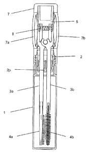
Figures 1, 2a and 2b depict one embodiment of an applicator according to the
present invention, and figure 3 is an exploded view thereof. This applicator
system
comprises a product container (1), a wiper system (2), two articulating stems
(3a, 3b),
two applicator heads (4a, 4b), a fulcrum (5), a spring (6), and an overcap (7)
that has
means to pressure the articulating stems. Figure 1 depicts the applicator in a
nearly
closed or rest position. Figure 2b depicts the applicator in an opened
position.
Container
A preferred embodiment of a container (1) comprises an inside wall or internal
surface (1f) that defines a reservoir (la) for holding a cosmetic or personal
care
product (P) that is to be applied by the applicator. The container further
comprises a
neck (1b) having an orifice (1c) which together form a passageway from the
exterior
of the container into the reservoir. The neck comprises screw threads (1d)
that
cooperate with an overcap (7). The neck is able to receive into itself a wiper
system,
and retain the wiper system against unintentional removal. Optionally, but
preferably,
the neck of the container may have a notch (1e) which can be used to secure
the
wiper housing (2a) against unwanted rotation (see figure 5). As will be seen,
it is
possible to make the container non-cylindrical, and still achieve acceptable
evacuation of product.
4
CA 02896712 2015-06-25
WO 2014/116390 PCT/US2013/078085
Wiper System
A wiper that can clean and prepare two applicator heads for use is secured in
the neck (1b) of the container (1) such that the wiper is free to rotate, but
not come
out of the neck. One preferred embodiment is shown in figures 3 and 4 wherein
a
wiper system (2) comprises a wiper housing (2a) and a wiper (2b). The wiper
housing
is roughly cylindrical and hollow. A lower portion (2c) of the wiper housing
is
designed to be secured in the neck (1b) of the container (1). This is
preferably
achieved with a friction fit that makes an effective seal, as commonly done in
the art,
but other means, such as adhesive, overmolding, or integral molding, may be
used.
The friction fit and seal between the wiper housing and neck may be enhanced
with a
sealing ring (2d), as shown on the lower portion of the wiper. The lower
portion also
comprises an internal ring (2e), which cooperates with the wiper (2b). An
upper
portion (2f) of the wiper housing extends above the neck of the container.
Preferred
embodiments of the wiper housing have a beveled surface (2q) near the top of
the
wiper housing, which cooperates with the overcap (7). When the wiper housing
is
seated in the neck, a flange (2g) rests against the top of the neck. The
flange
prevents the housing from being inserted too far into the container, and
improves the
seal between the neck and wiper housing. In preferred embodiments, the flange
also
cooperates with the overcap. In order to further facilitate the sealing
function, it is
preferable if the wiper housing is fashioned of an elastomeric material.
Optionally, but
preferably, the wiper housing may have a detent (2o, see figure 5) which
registers
with the notch (1e) of the neck (1b) of the container, to secure the wiper
housing
against unwanted rotation. The wiper depends from the wiper housing (2a) and
extends down into the neck of the container. An upper portion (2h) of the
wiper is
cylindrical and designed to fit into, and be retained in the lower portion
(2c) of the
wiper housing. The wiper has a circumferential channel (2i) for receiving
internal ring
(2e) of the wiper housing (2a). This fitment is sufficiently snug that the
wiper does not
back out of the housing during intended use, but the wiper is able to rotate
relative to
the housing.
In any embodiment of the wiper, a lower portion (2j) of the wiper is tapered,
and there are two passageways (2k, 21) through the wiper, for servicing
applicator
heads (4a, 4b) and stems (3a, 3b). The lower orifices (2m, 2n) of the wiper
are sized
5
CA 02896712 2015-06-25
WO 2014/116390 PCT/US2013/078085
to scrape the stems and applicator heads, as they pass through the wiper.
Preferably, the lower orifices have the same shape as the cross section of
stems (3a,
3b) In some preferred embodiments, the shapes and diameters of the two
orifices are
the same. In order to facilitate the wiping function, it is preferable if the
wiper is
fashioned of an elastomeric material.
Articulating Stems
Referring to figure 6, a tweezer type package according to the present
invention comprises two articulating stems (3a, 3b). Each stem has a distal
end (3c,
3d) and a proximal end (3e, 3f). The distal ends support applicator heads (4a,
4b).
The distal ends of the stems with the applicator heads attached are able to
pass
through the wiper housing, each stem/applicator head entering into one of the
passageways (2k, 21), and emerging into the reservoir (1a) of the container
(1).
Preferably, the length of the stems is such that in the fully assembled
system, the
applicator heads are able to scrape the internal surface of the bottom (1g) of
the
container.
A simple type of tweezers was described above. That type is often seen in
cosmetic packaging, such as that described in US6,325,071. Preferred
embodiments
of the present invention use a different type of tweezers, in which "rest
position"
means that the distal ends of the levers are touching in a pincer grip, while
application
of external pressure to the levers moves them apart and breaks the grip. When
not in
rest position, tension is stored in the articulation that tends to push the
levers toward
their resting, or grip, position. For example, in some preferred embodiments,
the
stems (3a, 3b), in between their proximal (3e, 3f) and distal (3c, 3d) ends
(but nearer
to their proximal ends) are formed to receive an axle in a pivoting
arrangement. For
example, near its proximal end, stem (3a) is formed as two circular collars
(3g).
Likewise, near its proximal end, stem (3b) is formed as one circular collar
(3h).
Preferably, collar (3h) of stem (3b) fits in between collars (3g) of stem
(3a). This
arrangement allows the applicator heads (4a, 4b) to line up so that they come
into
contact in rest position. The collars may be partially open, as shown, and
sufficiently
flexible so that they may be snapped onto an axle (5c). Once on the axle, the
two
6
CA 02896712 2015-06-25
WO 2014/116390 PCT/US2013/078085
stems are articulated about the axle, and the distal ends (3c, 3d) of the
stems move in
an arc, sometimes closer together, sometimes further apart.
Each of the proximal ends (3e, 3f) of the stems (3a, 3b) contacts the spring
(6),
such that the spring biases the proximal ends away from each other. For
example,
each stem may have a groove (3i, 3j), for receiving opposite ends of a spring
(6).
Each groove is even closer to the proximal end than the collar, i.e. each stem
articulates with the axle between its proximal and distal ends. In the fully
assembled
applicator, the spring pushes apart the proximal ends of the stems, which
brings
together the applicator heads (4a, 4b) located at the distal ends of the
stems. Under
the internal pressure of the spring, the two applicator heads come together in
a pincer
grip.
Preferably, the pincer grip is sufficiently strong to perform the intended
cosmetic application, but not so strong as to create any unpleasantness or
damage to
the user. For example, when applying mascara to the eyelashes, the applicator
heads are closed on the lashes near the base of the lashes. As the applicator
is
drawn toward the ends of the lashes, the pincer grip should be string enough
to
maintain firm contact with the lashes, but not so strong that it creates an
unpleasant
tugging of the lashes nor pulls out any eyelashes. Because the situation is
less
delicate, an applicator for applying dye to hairs of the head may use a
stronger pincer
grip than a mascara applicator. However, external pressure must be supplied by
a
user to release the pincer grip and/or separate the applicator heads.
Therefore, it is
preferable if the pincer grip is not so strong that a user has difficulty
separating the
applicator heads. The characteristics of the spring (6) may be altered through
trial
and error to achieve an acceptable pincer grip for the given application.
Applicator Heads
Applicator heads (4a, 4b) are attached to the distal ends of the stems (3a,
3b).
For example, an applicator head may form a snap fit with the distal end of a
stem, or
they may be joined by adhesive or welding or integrally molding. When disposed
in
the container, both applicator heads are loaded with the same product. So the
intention of the invention is that both applicator heads be used to apply the
same
product, generally to the same body feature, i.e. the eyelashes or eyebrows or
hair of
7
CA 02896712 2016-08-29
the head or lips or nails, etc. The applicator heads may be identical. For
example,
both applicator heads may be identical bristle brushes for applying mascara
(as
shown in figure 11), or identical combs for applying dye to the hair of the
head.
Alternatively, the applicator heads may be different. For example, one
applicator
head may be a bristle brush, and the other may be a comb for eyelashes (as
shown in
figures 6 or 9).
In this specification, brushes and combs are distinguished, as commonly
understood. Compared to combs, brushes have bristles that are generally more
flexible, more numerous, and extending in many directions. Compared to
brushes,
combs have tines that are generally more stiff, less numerous, and presented
in a
single row with all tines basically parallel. Combs with more than one row of
tines are
also known in the art, but the tines are still much sparser than bristles in a
brush. For
example, figures 6 and 7 show a brush applicator head (4b) with numerous
bristles
pointing in all directions, and a comb (4a) with two rows of parallel tines.
This
particular embodiment is a preferred one for hair applications. It is
especially effective
for applying mascara to the eyelashes. In principle, any type of applicator
head that
lends itself to being immersed in product and passed through a wiper may be
useful
in the present invention. For example, brushes include twisted wire core
types,
molded types and crimped types. Sponges may also be useful.
Preferably, the applicator heads (4a, 4b) are chosen to work together to apply
a cosmetic composition. It is possible to use the two applicator heads
sequentially,
first one and then the other. However, preferred methods of application take
advantage of the pincer grip that the applicator system is able to provide.
Preferably,
the applicator system is used to apply product to hair (H), which lends itself
to being
gripped between the applicator heads (4a, 4b), and drawn through applicator
heads
which apply a constant pressure, to evenly spread the product (see figure 7).
Fulcrum
A fulcrum is housed in the overcap. Referring to figure 8, the fulcrum (5)
comprises an upper portion (5a) and two downwardly depending legs (5b). An
axle
(5c), formed as a cylinder, extends from one leg to the other, and is fixedly
attached
thereto. As described above, the axle supports the collars (3g, 3h) of the
stems (3a,
8
CA 02896712 2016-08-29
3b). The space (5d) between the legs is provided so that the proximal ends
(3e, 3f) of
the stems can approach each other, which increases the range of motion of the
applicator heads.
Also depending from the upper portion (5a) of the fulcrum (5) is a housing
(50)
for the spring (6). In figure 8, the housing is formed as a bored out member.
When
assembled, the spring is disposed in the bore (5f), with either end of the
spring
extending beyond the member, so that the spring may contact the grooves (3i,
3j) of
the proximal ends (3e, 3f) of the stems (3a, 3b). As noted above, the
characteristics
of the spring should be chosen to achieve an acceptable pincer grip for the
intended
application. The force that the spring exerts on the stems depends on the
material of
the spring, its length, wire diameter, helix diameter and pitch. All of these
may be
varied to adjust the pincer grip, the length of the spring, however, should be
as
follows. Preferably, the spring is long enough to always be in contact with
both
grooves. More preferably, the spring is longer than the greatest separation
between
the proximal ends of the stems. When this is the case, the two applicator
heads (4a,
4b) will be forced together with some residual pressure to create a pincer
grip.
The fulcrum (5) is designed to fit into the overcap (7) and be retained in the
overcap. To facilitate that fit, the shape of the fulcrum may be complementary
to the
shape of the inside of the overcap. For example, both may be approximately
cylindrical. Also, the fulcrum may be provided with one or more raised snaps
(5h)
which cooperate with one or more detents (7e) on an inner surface of the
overcap, to
hold the fulcrum inside the overcap (see figure 9). Also, the fulcrum may be
provided with features that ensure that the fulcrum and overcap are rigidly
joined so
that they move as one. For example, the fulcrum may have ribs (5g) which grip
complementary grooves (7f) on an inner surface of the overcap. In this way,
when
the overcap is rotated, the fulcrum is also rotated, there being no
appreciable slippage
between the two.
()vernal)
Referring to figure 9, the overcap (7) is a housing for the fulcrum (5), as
just
described. As noted above, the inner surface of the overcap (7) may be
provided with
one or more detents (7e) which cooperate with one or more raised snaps (5h) of
the
9
CA 02896712 2016-08-29
fulcrum (5), to hold the fulcrum inside the overcap (see figure 8). Also, the
overcap
may be provided with features that ensure that the overcap and fulcrum move as
one.
For example, the inner surface of the overcap may have grooves (7f) which grip
complementary ribs (5g) of the fulcrum. In this way, when the overcap is
rotated, the
fulcrum is also rotated, there being no appreciable slippage between the two.
The lateral wall (7d) of the overcap is generally rigid, except for one or
more
flexible portions, preferably two flexible portions (7a, 7b) on opposite sides
of the
overcap. Each flexible portion fills a hole or window in the lateral wall.
When the
fulcrum (5) and stems (3a, 3b) are assembled into the overcap (7), then each
flexible
portion is located adjacent to one of the proximal ends (3e or 3f) of the
stems. When
the flexible portions are manually squeezed by a user, an external force is
applied to
the proximal ends of the stems. This force tends to compress the spring (6)
and force
the applicator heads (4a, 4b) apart. This is depicted in figures 2b and 11.
When the
externally applied force is removed or lessened, the spring expands, pushing
the
proximal ends of the stems apart, expanding the flexible portions of the
overcap, and
forcing the applicator heads toward rest position. Figure 12 depicts an
applicator in
rest position.
The lateral wall (7d) and flexible portions (7a, 7b) of the overcap (7) are
separate components. Preferably, the flexible portions are permanently
assembled
over the windows of the lateral wall. Preferably, the perimeter (7i) of each
flexible
portions is permanently assembled to the perimeter (7j) of the window of the
lateral
wall. For example, the perimeter of the flexible portions may be snap fitted
or glued to
the perimeter of lateral wall portions, but this type of assembly is
relatively labor
intensive. More preferably, the rigid and flexible wall portions are formed
using bi-
injection molding techniques. This process is carried out by either
simultaneously or
successively injecting different molten materials into separate sections of a
mold until
the separate components meet to fill the mold. Upon cooling the mold, the
different
materials fuse together where they intersect, thus providing a single article
having
different materials in specific sections. The material comprising the rigid
wall of the
overcap may be polyethylene, such as low density polyethylene, high density
polyethylene, or blends of varying density polyethylene; polypropylene;
polyvinylchloride; polyesters; polyamides; nylons; or blends of other
plastics, such as
a polycarbonate/polypropylene mixture. Preferably, the rigid frame is composed
of
CA 02896712 2015-06-25
WO 2014/116390
PCT/US2013/078085
polypropylene. The flexible portions are preferably elastomeric or
thermoplastic
material, such as silicone, ethylene vinyl acetate copolymer (EVA), polyether
amide
block copolymer, polyester elastomer, ethylene propylene diene monomer rubber
(EPDM), polyurethane, styrene butadiene styrene (SBS), styrene isoprene
styrene,
styrene ethylene-butylene styrene, styrene ethylene-propylene styrene, latex,
and
nitrile butadiene rubber.
The overcap (7) also acts as a closure for the container (1) through its
cooperating threads (7c), and provides optional, but preferred sealing
features. For
example, in preferred embodiments, when the overcap is screwed down onto the
container, the bottom (7g) of the overcap comes to bear down on the flange
(2g) of
the wiper housing (2a), creating a seal between the flange and the overcap.
Furthermore, preferred overcaps have a tapered surface (7h) above the threads.
When the overcap is screwed down onto the container, then the tapered surface
comes to bear against the beveled surface (2q) near the top of the wiper
housing,
thus forming another seal between the wiper housing and the overcap.
Furthermore,
the bi-injection molding process described above is also preferred because
joining the
flexible and rigid portions in this way ensures that there will be no air gaps
in the
finished overcap. With all the various means of forming seals, as herein
described,
gas transmission and product weight loss from a closed container of the
present
invention are minimized, and expected to be equal or superior to anything in
the prior
art.
Use
As the overcap (7) is screwed about the neck (1b) (that is, screwed onto or
unscrewed from the container 1) the stems (3a, 3b) and applicator heads (4a,
4b)
revolve around the longitudinal axis (A) of the neck (1b). Because the stems
contact
the wiper (2b), the wiper rotates around the same axis. The wiper housing (2a)
is
prevented from rotating, as described above, so that the seal that the wiper
housing
makes with the neck of the container is not compromised. Once the overcap and
container are disconnected, the applicator heads may be raised out of the
reservoir.
In doing so, the stems and applicator heads are wiped by the orifices (2m, 2n)
of the
wiper (2b). Product is smoothed over the applicator heads, and excess product
is
11
CA 02896712 2015-06-25
WO 2014/116390 PCT/US2013/078085
removed from the applicator heads and stems. The applicator is ready for use.
If not
already doing so, a user squeezes the flexible portions (7a, 7b) which causes
the
applicator heads to separate. A body part, such as eyelashes, is brought
between the
applicator heads, and then the pressure on the flexible portions of the
overcap is
released. This allows the applicator heads to close against each other and
grip the
eyelashes or other body part with constant pressure. This is an advantage over
those
tweezer type applicators that require the user to maintain external pressure
during
application, because pressure will vary as the user manipulates the
applicator, giving
an uneven application. While in the grip of the applicator heads, the
applicator is
drawn along the surface, spreading product on the surface with constant
pressure.
For eyelashes, a user will draw the applicator heads away from the eyelid,
coating the
eyelashes along the way until the applicator heads reach the end of the
eyelashes
and come off the lashes. The user may squeeze the flexible portions of the
overcap
to separate the applicator heads and repeat the process on the same of
different
lashes. Of course, the applicator can also be used without gripping a part of
the
body. The surfaces of the applicator heads that do not meet in rest position
may be
used according to their typical use. Thus, product may be spread evenly with
the
pincer grip, and then touched up in a more conventional fashion. When the user
is
finished or when she needs more product, she may return the applicator heads
to the
reservoir. Ideally, each applicator head will be guided into one of the
passageways
(2k, 21) of the wiper without having to apply any pressure to the flexible
portions of the
overcap.
Some Features
Figure 1 is a cross section of an applicator system according to one preferred
embodiment of the present invention. The overcap (7) is fully seated on the
container
(1). A few thing may be noted. First, the applicator heads (4a, 4b) are shown
as
separated, i.e. not fully in the rest position. This may happen if the wall
(2p) between
the two passageways (2k, 21) of the wiper (2b) is sufficiently strong to hold
the stems
(3a, 3b) apart. When disposed in the container, some separation between the
applicator heads is preferred, because it enables the entire applicator head
to contact
and receive product. Otherwise, those surfaces of the applicator heads that
contact
12
CA 02896712 2015-06-25
WO 2014/116390 PCT/US2013/078085
each other would have less product, and these are exactly the most important
surfaces for applying product with the present applicator system. This is an
advantage over those tweezer type applicators that mash the two applicator
heads
together when in the reservoir (see US5,007,442, for example). Product is
inhibited
from contacting those parts of the applicator heads that are pushed against
each
other.
For another useful feature, we note that even when the overcap (7) is fully
seated on the container (1), a user is able squeeze the flexible portions (7a,
7b) of the
overcap, and force the applicator heads to separate until they contact the
inside wall
(1f) of the container. Doing so, may deform the wiper orifices (2m, 2n)
slightly, but if
the wiper (2b) is elastomeric, this should not be a problem. Thus, the
applicator
heads can be held against the internal wall of the container as the overcap is
being
unscrewed. In this position, the applicator heads will wipe a significant
portion of the
container wall, and evacuate product that is not normally evacuated.
The feature just descried provides an opportunity to make the reservoir (and
container) non-cylindrical. Suppliers almost always use a cylindrical
container for full
size, saleable mascara packages. They do this out of necessity, because it is
usually
not possible to get efficient product evacuation from containers of any other
shape.
But with the present invention, and as shown in figure 10, the reservoir (10a)
(and
container 10) may be tapered outward, having a larger diameter at the bottom
(10g)
than at the neck (10b). The applicator heads could be made to expand to scrape
the
internal surface (10f) of the container. As the applicator heads are withdrawn
from
the reservoir, the walls would push back against the applicator heads, pushing
them
closer together until they reach the wiper. Container shapes are not limited
to simple
tapering, and a wide variety of shapes will be more efficiently evacuated with
an
applicator according to the present invention. However, by squeezing the
flexible
portions, the applicator heads of the present invention are especially able to
scrape
the internal surface of any cylindrically symmetric reservoir. Therefore, non-
cylindrical
reservoirs that have cylindrical symmetry are preferred when efficient
evacuation is
important. Such shapes may be regular, such as spheres, cones, and cylinders,
but
may also be an irregular solid of revolution.
13
CA 02896712 2015-06-25
WO 2014/116390 PCT/US2013/078085
The applicator system thus described is particularly useful for making up
hair.
Also, although the invention has been described in terms of make up products,
other
products such as treatment products may be applied in the same manner.
The tweezer applicator system described herein provides improvements of
prior art applicators, especially those for applying mascara. The system may
use a
standard container of the type commonly used, and the container may be filled
to
conventional levels. The tweezer grip is achieved without the application of
external
pressure, which gives a consistent grip and more even application of product.
The
present applicator is able to evacuate more product from the container than
prior art
applicators, even for some non-cylindrical containers.
14