Note: Descriptions are shown in the official language in which they were submitted.
CA 02897108 2015-07-02
WO 2014/116554
PCT/US2014/012241
BACKUP BULLET SEAL WITH ACTUATION DELAY FEATURE
Inventor: Sibu Varghese
FIELD OF THE INVENTION
[0001] The field of the invention is high pressure and high temperature
seals and more particularly sealing arrangements with backup feature and
more particularly a backup that has a delay feature to energize.
BACKGROUND OF THE INVENTION
[0002] Bullet seals are described in detail in USP 5,611,547 where seals
80 and 82 are disposed in mirror image with an o-ring 78 between them to
handle pressure differential in opposed directions. These seals have a
generally pointed end and an opposite finned end adjacent the o-ring. These
seals were designed to replace the stacks of chevron shaped seals shown in
FIG. 1 of that patent. There were no backup seals used for pressure
differentials in a given direction and no efforts to actuate the finned end
beyond the axial pressure from fluids in the string. Other related seal
designs
are shown in USP: 5,879,010; 7,341,258; 5,524,905; 7,363,981; 6,318,729;
7,819,184 and 7,401,788.
[0003] Of the bullet seals that have been deployed in the past there
have
been issues with reliable performance particularly where significant
temperature fluctuations of over 200 degrees F could occur. These seal
assemblies had no backup as illustrated in FIG. 1 with opposed bullet seals 10
and 12 separated by an o-ring 14 and disposed in a mirror image layout for
opposing pressure differentials from either an uphole or a downhole direction.
The past design focused on ease of assembly and a need to optimize a sealing
system in a small confined space. The bullets were installed in an activated
configuration. In some applications backup bullet seal pairs were used where
the primary and the backup seals were identically configured and installed in
a
configuration that application of a net differential pressure in one direction
activated both the primary and secondary seals due to axial compression
through the o-ring in between opposed seal pairs and more rigid end rings
adjacent the tapered ends of the seals.
[0004] What is needed and provided by the present invention is an
assembly of bullet seals with a backup that is delayed in being deployed using
1
CA 02897108 2016-09-27
primarily a temperature effect on a material that prevents advancement of a
ring between end fins. The backup seal is not actuated until pressure is
communicated to it such as by a failure of a primary seal and then there is
the
effect of temperature of well fluids to allow the t-shaped ring to advance as
the
material on the leading branch of the t-shaped ring softens to allow pressure
differential to advance the ring and spread the end fins of the bullet seal to
enhance its performance. These and other features of the present invention
will
be more readily understood by those skilled in the art from a review of the
detailed description of the invention and the associated drawings while
recognizing that the full scope of the invention will be determined by the
appended claims.
SUMMARY OF THE INVENTION
100051 A sealing system features a primary and secondary bullet seals
where the secondary seal is preferably bidirectional and is activated to
spread
fins with a t-shaped ring that is driven with differential pressure to advance
after temperature exposure softens a stop material on the extending portion of
the t-shaped ring. Opposed t-shaped rings are disposed at ends of the backup
ring that have fins at both ends. Advancement of the t-shaped ring spreads the
fins and retains them in the spread condition for enhanced sealing. Optionally
the primary seal can also be actuated with a similar t-shaped ring with a
temperature sensitive delay feature.
10005a1 Accordingly, in one aspect there is provided a seal assembly for a
subterranean tool having a bullet shaped cross-section for an annular space
having
an uphole and a downhole end for subterranean use, the seal assembly
comprising
opposed fins on at least one end of at least one seal body that are spaced
apart to
define a groove therebetween; at least one ring having an extending branch
positioned in alignment with and initially substantially out of said groove
upon
assembly to the subterranean tool; and at least one selective travel stop
located
outside said groove to prevent movement of said extending branch into said
groove upon installation of the seal assembly into the subterranean tool, said
travel
stop being defeated while remaining outside said groove at a subterranean
location
for the subterranean tool for movement of said extending branch into said
groove
to deliver a sealing force to said fins at the subterranean location.
2
CA 02897108 2016-09-27
= .
BRIEF DESCRIPTION OF THE DRAWINGS
[0006] FIG. 1 is a prior art installation of opposed bullet seals
located on
opposed sides of a fixed support location;
[0007] FIG. 2 shows a primary seal used in conjunction with a
bidirectional
bullet seal as backup when the backup seal is not activated; and
[0008] FIG. 3 is the view of FIG. 2 with the backup bullet seal
activated by
enabled advancement of the t-shaped rings into the space between the fins.
DETAILED DESCRIPTION OF THE PREFERRED EMBODIMENT
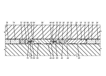
[0009] FIG. 2 illustrates a primary bullet seal 16 that has a
tapered nose 18
and opposed fins 20 and 22 respectively on the outside diameter and the inside
diameter. There are outside and inside sealing areas 24 and 26 respectively. A
circular groove 28 divides the fins 20 and 22. A leading end ring 30 has a
2a
CA 02897108 2015-07-02
WO 2014/116554
PCT/US2014/012241
taper 32 to accept the tapered nose 18. This ring is typically plastic that
has the
needed properties of compressive strength and tolerance to well fluids and
anticipated temperature. The material can be PEEK for example. Another ring
34 that is typically metal is disposed ahead of ring 30 for backup. On the
other
end of the primary bullet seal 16 is an o-ring 36.
[0010] Adjacent o-ring 36 is t-shaped ring 38 that has a concave curved
end 40 that contacts o-ring 36 and a branch component 42 that is formed to fit
into groove 44 that is disposed between outside and inside fins 46 and 48
respectively. However, internal and external rings 50 and 52 are disposed on
opposed sides of the branch component 42 with the purpose of keeping the
branch component 42 out of groove 44 until rings 50 and 52 respond to
thermal or other inputs and soften or weaken or collapse or dissolve or
otherwise get out of the way so that a net force applied from the downhole
side represented by arrow 54 in FIG. 3 allows the branch component 42 to
advance into groove 44. That advancing spreads the fins 46 and 48 by about
10-15 thousands beyond the dimension at 56, in a laterally unrestrained
condition.
[0011] At the opposite end of bidirectional backup seal 58 there are
mirror
image fins 60 and 62 to fins 46 and 48. Fins 60 and 62 are separated by groove
64 with a similar arrangement using t-shaped ring 66 with rings 68 and 70 as
previously described for the other end of the backup seal 58. Adjacent to the
t-
shaped ring 66 is o-ring 72 which is followed by plastic ring 74 made of
PEEK or other material suitable for the load, chemical exposure and thermal
conditions downhole. Finally another support ring 76 that is generally
metallic
follows adjacent ring 74.
[0012] Loading comes primarily from downhole represented by arrow 54.
That pressure compresses the assembly shown in FIG. 2. Normally the sealing
function is carried out by the primary seal 16 with force transferred to o-
ring
36 and into t-shaped ring 38 and then through rings 50 and 52 into the backup
seal 58 and through the mirror image rings 68 and 70 to t-shaped ring 66 and
onto o-ring 72 and ultimately against rings 74 and 76 that are backstopped by
a fixed support that is not shown. With the primary ring 16 functional against
pressure from downhole the well fluids and their temperature will not reach
3
CA 02897108 2015-07-02
WO 2014/116554
PCT/US2014/012241
rings 50, 52, 68 and 70 and they will retain their structural rigidity.
However,
if there is a failure of the seal 16 the fluids from downhole will reach these
rings and cause them to weaken so that they no longer impede the relative
movement with respect to seal 58 and the branch components 42 and 78 can
respectively then enter grooves 44 and 64 to apply a radial sealing force to
the
respective pair of fins that define the grooves 44 and 64 to enhance the
effectiveness of the backup seal 58 to pressure differential in opposed
directions. This position is shown in FIG. 3.
[0013] Those skilled in the art will appreciate that there are
variations
contemplated on the illustrated assembly in FIGS. 2 and 3. For example a
mirror image of the entire assembly can be located further uphole above ring
76 and can function in a similar way to retain differentials pressures from
uphole in the direction of arrow 80. Alternatively, the entire assembly can be
as depicted in FIGS. 2 and 3. The primary seal 16 can be outfitted with its
own t-shaped ring similarly shaped as ring 38 with thermally responsive rings
50 and 52 but with a branch component such as 42 oriented toward groove 28
for selective entry therein when the right conditions of compressive force and
predetermined temperature are reached. Such a ring would be located between
o-ring 36 and fins 20 and 22.
[0014] The dimensions of the seals 16 and 58 at outer locations 24 and
56
are preferably the same. Rings such as 50 or 52 can be a rubber or elastomer
or a polymer such as shape memory polymer.
[0015] Those skilled in the art will appreciate that the delay feature
provided by rings such as 50 and 52 will facilitate assembly since there will
be
negligible resistance to installation during the assembly process with a
reduced
chance for distortion or twisting in the bullet seals that make up the sealing
assembly. Premature activation can impede the installation effort and can
cause damage such as tears or cracks that can compromise the seal in high
temperature applications with conditions reaching to 350 degrees F or more
and pressures in thousands of pounds. The driving into a groove of a branch
component such as 42 is a more assured way for enhancing sealing force that
pushing an o-ring against fins because the nature of the displacement that is
obtained is more certain whereas the o-ring can distort in a variety of ways
4
CA 02897108 2015-07-02
WO 2014/116554
PCT/US2014/012241
that will not necessarily deliver the desired fin movement or will not retain
the
initial displacement in a manner that filling the groove with the branch
component that in essence widens the groove as the component is advanced
and stays put thereafter to enhance the sealing in the region of the fins. The
backup seal 58 winds up only fully actuated at a later time than the initial
assembly and likely well after deployment upon exposure to predetermined
compressive force and temperature of well fluids.
[0016] One condition that can make a primary seal 16 fail can be
dramatic
temperature changes with associated dimensional changes that can be
experienced as different procedures are undertaken such as cycles of steam
injection and downtime. In such circumstances with differentials in
temperature of over 200 degrees F that may make a primary seal fail to hold
pressure, the actuation of the secondary bidirectional seal 58 can prevent a
leakage situation. Seal 58 can also be optionally unidirectional and
optionally
more than a single seal 58 can be used in a configuration to prevent leakage
in
a given direction apart from the option of a full mirror image layout for the
assembly shown in FIGS. 1 and 2.
[0017] The above description is illustrative of the preferred embodiment
and many modifications may be made by those skilled in the art without
departing from the invention whose scope is to be determined from the literal
and equivalent scope of the claims below: