Note: Descriptions are shown in the official language in which they were submitted.
CA 02897473 2015-07-08
WO 2014/117957 PCT/EP2014/000296
1
Otoscope
FIELD OF THE INVENTION
The invention refers to an otoscope comprising a handle portion allowing a
user to
manipulate the otoscope during its application, and further comprising a head
portion exhibiting a substantially tapering form extending along a
longitudinal axis of
the head portion, wherein the head portion has a proximal end adjacent to the
handle portion and a smaller distal end configured to be introduced in an ear
canal
of a patient's outer ear.
An otoscope (sometimes also called "auriscope") is a medical device which is
used
to look into ears. The corresponding method of doing so is called "otoscopy".
Otoscopy is a standard medical examination technique established more than 100
years ago. Medical students learn otoscopy early in their studies during the
practical
course in physiology. Typical diagnoses based on otoscopic examination are:
otitis
media (OM), otitis media with effusion (OME), otitis externa, and eardrum
perforation. OME is defined by the presence of middle ear effusion, i.e. a
liquid
behind an intact tympanic membrane without signs or symptoms of acute
infection.
OME is one of the most frequent pediatric diagnoses. However, otoscopy is also
used to generally identify and observe object's in the ear, such as earwax,
hair and
the eardrum.
A typical otoscope 10' as used for decades in otoscopy is shown in figure 3.
The
otoscope 10' comprises a handle portion 12' allowing the user to manipulate
the
otoscope during its application. The term "to manipulate" in this context
refers to
CA 02897473 2015-07-08
WO 2014/117957 PCT/EP2014/000296
2
different kinds of manipulation, such as ¨ but not limited to ¨ holding the
otoscope,
aligning the otoscope with respect to the patient's ear, and turning on or off
a light.
The otoscope 10' further comprises a head portion 14' connected to the handle
portion 12'. The head portion 14' exhibits a substantially tapering form ¨
usually a
conical form ¨ extending along a longitudinal axis A' of the head portion 14'.
The
head portion 14' is substantially comprised of an empty funnel, wherein the
tip of
the funnel typically has a relatively small diameter, e.g. about 3 millimeters
for
children. Furthermore, the head portion 14' has a proximal end 16' adjacent to
the
handle portion 12' and a smaller distal end 18' configured to be introduced in
an ear
canal C of a patient's outer ear. The term "end" in this context does not mean
a
single point but rather refers to a region or section of the head portion 14',
wherein
the proximal end 16' is located opposite to the distal end 18' with respect to
the
longitudinal axis A'. The ear canal C is partly surrounded by soft connective
tissue
C1 and ¨ further down towards the middle ear ¨ partly by hard bone C2.
The working principle of the known otoscope is typically to observe and
simultaneously illuminate the patient's eardrum ED through the empty funnel
with
the 3mm tip pushed deeply into the ear canal C. Normally, the eardrum ED is
not
visible from outside the ear, due to the natural curvature of the ear canal C.
In order
to overcome the natural curvature of the ear canal C, the skilled physician
has to
carefully pull the outer ear upward and to the back while carefully pushing
the tip of
the funnel as deeply as necessary to observe the eardrum. The ear canal C has
to be
deformed (especially straightened) in such a way that the physician has a free
view
onto the eardrum ED along the optical axis of the otoscope 10', wherein the
optical
axis corresponds to the longitudinal axis A' of the head portion 14'. The
optics of an
otoscope is situated only at the wider end of the funnel at its proximal end
16' and
essentially consists of a lamp and a lens (not shown) to magnify the image of
the
eardrum ED.
The otoscopy procedure needs manual skills and significant training to make it
possible to carefully push the funnel into the ear canal C while looking
inside and
manipulating the curvature of the ear canal C by pulling the ear. For example,
it is
CA 02897473 2015-07-08
WO 2014/117957 PCT/EP2014/000296
3
very important for the trained physician to brace the hand holding the
otoscope
against the patient's head to avoid injury to the ear canal C by placing the
index
finger or little finger against the head. In particular in young children ¨
where the
inner part of the ear canal is relatively short and sudden head movement
during the
examination may occur ¨ there is a risk of penetration of the very sensitive
ear canal
skin or even of the eardrum ED. Besides pain and handicapped hearing, such an
injury may even induce cardiovascular complications through a vagal over-
stimulation and therefore has to be avoided by all means.
Furthermore, especially in an inflamed ear, the mechanical manipulation of
"straightening" the ear canal C typically causes considerable discomfort or
even
pain, rendering the examination of an infant even more difficult.
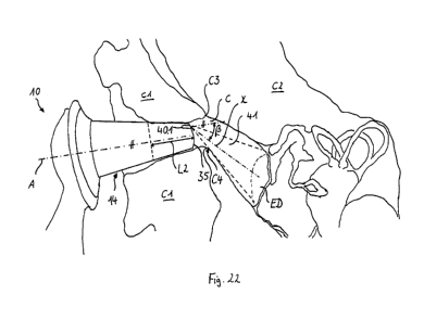
Figure 4 illustrates that with a distal tip of the otoscope 10' being
positioned far
within the bony part C2, the ear canal C has to be "straightened" considerably
in
such a way that the longitudinal axis A is directed onto the eardrum ED, at
least
approximately. The distal tip of the head portion 14' is supported within the
bony
part C2, such that a proximal end of the head portion 14' contacting the soft
connective tissue C1 can push the soft connective tissue C1 downwards. The
head
portion 14' is shaped such that there remains the danger of touching the
eardrum
ED.
BACKGROUND OF THE INVENTION
For the above reasons, reliably and securely handling an otoscope of the art
is
currently subject to only well trained physicians and not amenable to the
larger
community of practitioners. A study recently published in the US as a result
of a
survey has shown that even physicians often fail to (correctly) determine the
status of
e.g. the subject's eardrum or fail to correctly interpret the image provided
by the
otoscope (i.e. correct and meaningful object recognition). Such failures
result in
misinterpretation of the status of the inner ear canal or the eardrum. As a
consequence, e.g. over-medication with antibiotics for treating supposed
CA 02897473 2015-07-08
WO 2014/117957 PCT/EP2014/000296
4
inflammations of the eardrum occurs, because physicians tend to err on the
side of
caution, or meaningless image interpretation occurs.
Notably, there also exist other otoscopic devices, as e.g. video otoscopes,
allowing a
skilled expert to capture images of the subject's eardrum and the ear canal.
Such
video otoscopes comprise a bundle of light guides extending from the distal
end of
the head portion to a CCD-chip located remote from the distal end. The
achievable
resolution of the images depends on the number of light guides. In order to
obtain
images having a satisfying resolution, a significant number of individual
light guides
must be provided rendering devices by far too expensive for routine care.
Moreover,
all of the known video otoscopes having the CCD-chip located remote from the
distal end of the head portion require superior handling skills by he
physician. For
the above reasons, they are not configured and suitable for domestic use by a
larger
community of practitioners, nor use by laypersons.
All otoscopes currently on the market ¨ including video otoscopes ¨ generally
are
based on the following fundamental design: a relatively thin open funnel.
Length,
angle, field of vision and size of the funnels are essentially similar for all
marketed
otoscopes. As a result of these common characteristics, ease of use (due to
safety
issues) is limited for such devices. Methods for reliable detection of objects
in the ear
canal, including the eardrum, are remarkably intricate with such known
otoscopes.
Consequently, until today otoscopy has almost been exclusively applied by
medical
doctors. And even among medical doctors, only a minor percentage is
sufficiently
trained to carry out otoscopy in a reliable and appropriate way. However,
since otitis
media is the most frequent disease causing high fever in young children, and
to
exclude otitis media, especially OME, is a major reason for seeing a
pediatrician,
there is an urgent need for a parental check of the ear. Parents may also
benefit from
an otoscope that can be securely used by laypersons at home in order to check
whether an ear canal of their child is blocked by massive earwax and/or
foreign
objects.
CA 02897473 2015-07-08
WO 2014/117957 PCT/EP2014/000296
Prior art document US 5 910 130 A describes an otoscope with a miniature video
camera or a solid-state imager, e.g. a CCD or CMOS. A light source can be
provided
in the form of a continuous ring of light emitting fibres. The head portion of
the
otoscope has to be introduced far into a straightened ear canal in order to
observe
5 the eardrum.
Prior art document US2013/027515 A1 describes an ear canal side scanner with a
small diameter comprising a camera including e.g. a CCD or CMOS chip. The
camera can be arranged at a tip of a probe of the side scanner. The scanner
allows
for side scans of lateral surfaces of the ear canal. The tip of the side
scanner is
positioned close to the eardrum before scanning.
Prior art document US 2011/063428 A1 describes a medical device (an endoscope)
comprising illumination means and a video camera based on wafer level optics,
e.g.
a solid state imager, and having a maximum outer diameter of less than 3.2 mm.
Prior art document EP 2 289 391 A1 describes an otoscope with a head portion
and
a fastening ring for reversibly mounting the head portion to a display
portion.
Prior art document EP 2 277 439 A2 describes a clinical ear thermometer
including
an image sensor which is positioned radially offset, especially in order to
provide a
cavity in which a temperature sensor can be arranged at a distal end.
It is therefore an object of the present invention to provide an otoscope that
allows
for domestic application by laypersons and medical doctors without extensive
otoscopy training and without any ¨ or at least with a significantly reduced ¨
risk of
causing injuries to the patient. In particular, it is an object of the present
invention to
provide an otoscope that allows for automatically identifying objects within
the ear
canal, e.g. the eardrum, substantially irrespective of the relative position
of a head
portion of the otoscope within the ear canal. The object of the present
invention can
also be describes as to provide an otoscope that allows for identifying
objects with
high reliability, even if the otoscope is applied by laypersons.
CA 02897473 2015-07-08
WO 2014/117957 PCT/EP2014/000296
6
This object is achieved according to the present invention by an otoscope
exhibiting
the features of claim 1 or claim 19 or claim 20. Preferred embodiments
represent the
subject-matter of the dependent claims.
In particular, this object is achieved by an otoscope of the generic type as
described
above, wherein the otoscope further comprises an optical electronic imaging
unit
positioned at the distal end of the head portion, especially at a distal tip
of the head
portion, wherein the electronic imaging unit exhibits at least one optical
axis which
is positioned radially offset from the longitudinal axis, and wherein the
distal end is
configured for accommodating the electronic imaging unit in such a way that
the
radial offset can be maximum with respect to the diameter of the distal end.
The
larger the radial offset, the better the view onto the eardrum, even in case
the distal
end is positioned only in a transition area between soft connective tissue and
hard
bone confining the ear canal. The electronic imaging unit may be arranged such
that
the radial offset is maximum with respect to the diameter of the distal end,
in order
to allow the otoscope for effectively looking around a curvature of the ear
canal.
Providing a small electronic imaging unit at the distal end of the head
portion
exhibiting at least one optical axis which is radially offset allows to "see"
the
patient's eardrum without the need to deform the patient's ear canal, or at
least
without having to deform the ear canal to such an extent as with the above
described conventional otoscope. The reason for this is that there is no need
for the
"viewing direction" of the electronic imaging unit to correspond to the
longitudinal
axis of the head portion of the otoscope. Rather, the radial offset can ensure
that
there is a line of sight onto the eardrum even if the ear canal is not
straightened,
allowing the device to "look around the corner". In particular, in many cases,
the ear
canal of the outer ear is not straight-lined, but exhibits at least one
curvature,
especially at a transition area or transition point between soft connective
tissue and
hard bone confining the ear canal. The "corner" is provided by this curvature.
In
particular, virtually almost always, the ear canal has an S-shaped (sigmoid)
form with
a first curvature and a second curvature, the second curvature being closer to
the
CA 02897473 2015-07-08
WO 2014/117957 PCT/EP2014/000296
7
eardrum than the first curvature. Particularly, the second curvature of the
ear canal
obstructs any optical line of sight or visual communication of an otoscope
which is
not introduced as far as at least some millimeters within the bony part of the
ear
canal. The "corner" can be defined as the second curvature of the ear canal.
In
particular, in a distal direction, the second curvature leads to the bony part
of the ear
canal. A transition point or area between soft connective tissue and hard bone
is
arranged at this second curvature. The second curvature leads into the section
of the
ear canal which is exclusively confined by hard bone. Preferably, the
transition area
can be defined as an area of about a few millimeters distal to (behind) and
about a
few millimeters proximal to (in front of) a curvature, especially Omm to 5mm
or
lmm to 3mm.
Such an electronic imaging unit can provide an otoscope which can be used by
laypersons, without extensive otoscopy training and with a significantly
reduced risk
of causing injuries, especially with a significantly reduced risk of
irritation of the
patient's tissue, e.g. the tissue within the hard bone section of the ear
canal. Such an
electronic imaging unit allows for observing the eardrum substantially
irrespective
of the relative position of a head portion of the otoscope within the ear
canal,
especially irrespective of any specific insertion depth into the bony part of
the ear
canal, i.e. the section confined by hard bone. As the otoscope is arranged for
"looking around the corner or curvature", the layperson does not have to
introduce
the head portion as far as a section of the ear canal which is confined by
hard bone.
While in traditional otoscopy, the physician has to introduce the otoscope at
least as
far as some millimeters within the bony part of the ear canal, i.e.
considerably
further inwards than the second curvature, an otoscope according to the
present
invention can be positioned adjacent to the second curvature. In traditional
otoscopy, the otoscope is necessarily introduced far into the bony part of the
ear
canal, especially in order to provide a kind of support or rest or anchoring
point at
the distal tip of the otoscope. Once the distal tip of the otoscope is
supported within
the bony part, the physician can apply a leverage on the handle portion of the
otoscope, in order to straighten the ear canal and in order to ensure an
optical line of
sight onto the eardrum. But, this kind of "alignment" of the otoscope or this
kind of
CA 02897473 2015-07-08
WO 2014/117957 PCT/EP2014/000296
8
straightening out the ear canal is painful. In contrast, the otoscope
according to the
invention does not require such an "alignment" or straightening.
According to one specific embodiment, the electronic imaging unit may also
exhibit
a field of vision with a wide angle, such that the eardrum is visible even in
case the
longitudinal axis is inclined with a large angle with respect to an
longitudinal axis of
the ear canal. According to another embodiment, the optical axis of the
electronic
imaging unit may also be arranged at an angle with respect to the longitudinal
axis,
allowing the device to "look around the corner" more effectively. An
additional or
alternative reason is that the field of vision of an electronic imaging unit
provided at
the distal end of the head portion can be much greater than the field of
vision
achievable with the relatively acute empty funnel of the otoscope according to
the
prior art.
Furthermore, in contrast to conventional otoscopes, the distal end of the head
portion of the otoscope according to the present invention does not need to
have a
conical shape with a relatively thin open funnel, which shape bears the risk
of
introducing the distal end of the head portion too far into the ear canal, so
as to
cause serious injuries to the patient. Instead, the outer shape of the distal
end of the
head portion can be designed in such a way that it is practically impossible
to
introduce it too far into the ear canal. Thus, the otoscope according to the
present
invention can be securely and reliably operated even by laypersons without the
risk
of causing injuries to the patient. In particular, the otoscope according to
the present
invention allows for observing the eardrum substantially irrespective of the
relative
position of a head portion of the otoscope within the ear canal, especially
irrespective of any specific insertion depth into the bony part of the ear
canal, i.e. the
section confined by hard bone. The distal end can be provided with a shape
which
allows for mechanically preventing any contact with the eardrum. In
particular, the
distal end can be provided with a relatively large diameter, which allows for
both a
large radial offset and a mechanical stop within the ear canal at a position
relatively
far away from the eardrum.
CA 02897473 2015-07-08
WO 2014/117957 PCT/EP2014/000296
9
The distal end may exhibit a cavity for at least partially accommodating the
electronic imaging unit such that the radial offset can be maximum within the
lateral
walls or lateral surface of the distal end, preferably at least half the
radius (half of half
the radial dimension) of the distal tip, more preferable at least 2/3 of the
radius (or
2/3 of half the radial dimension) of the distal tip.
According to one embodiment, the radial offset is at least factor 0.25 of the
radial
dimension of the distal end, preferably at least factor 0.3, more preferable
at least
factor 0.35. Such a relatively large radial offset can ensure positioning the
optical
axis in a favorable eccentric observation point within the ear canal, even in
case the
distal tip in introduced only as deep as a transition point between soft
connective
tissue and hard bone.
According to one specific embodiment, the at least one miniature camera and/or
the
infrared sensor unit are positioned at a distance of less than 3mm, preferably
less
than 2mm, more preferable less than lmm, from the distal tip. Such an
arrangement,
especially as close as possible to the distal tip, allows for providing the
maximum
eccentricity within the ear canal, allowing for effectively "looking around
the
corner".
According to one embodiment, adjacent to an inner lateral surface of the
distal end,
the head portion exhibits a cavity for accommodating an optical component
(e.g. a
camera, a lens or an image sensor) of the electronic imaging unit defining the
at least
one optical axis, such that the optical axis can be arranged as close as
possible to the
inner lateral surface of the distal end. Such a cavity ensures maximum radial
offset.
Preferably, the cavity at least partially is confined by the inner lateral
surface of the
distal end.
Preferably, the electronic imaging unit or at least an optical component
thereof, e.g.
a lens, is positioned at the most distal part of the head portion. In
particular, the
electronic imaging unit can be in contact with a front side or front face of
the head
portion, or the electronic imaging unit can provide a front side or front face
of the
CA 02897473 2015-07-08
WO 2014/117957 PCT/EP2014/000296
head portion. This enables positioning the electronic imaging unit most distal
within
the ear canal without the need of introducing the head portion deep into the
ear
canal.
5 The otoscope according to the present invention may comprise further
features that
are provided, for example, by modern digital photo cameras. For example, the
otoscope may comprise visual output means, such as a display, and/or acoustic
output means, such as a loudspeaker, and/or a storage card slot for inserting
a
storage card to store the acquired images, and/or a cable connection port,
such as an
10 USB-port, and/or a wireless connection, such as Bluetoothe, WIFIO,
and/or an
energy supply, such as a battery.
Preferably, an "optical axis of the electronic imaging unit" is an axis which
extends
from a most distal point of the electronic imaging unit in a distal direction,
especially
towards the eardrum, wherein its orientation is not modified any more by any
optical
components. The "optical axis of the electronic imaging unit" of an electronic
imaging unit preferably is the optical axis with the largest radial offset.
Preferably, the at least one optical axis is arranged as close as possible to
an inner
lateral surface of the distal end. Thereby, the radial offset can be
maximized.
The electronic imaging unit may comprise a video camera defining an optical
axis,
preferable a wide angle color video camera. The term "wide angle" in this
context
refers to angels of at least 80 , preferably of at least 1 1 0 , e.g. 12 0 .
Such wide angle
cameras allow detection of the patient's eardrum, even if the optical axis of
the
camera is not directly centered to the eardrum and even if the eardrum is
relatively
remote from the camera, compared to the distance between the eardrum and the
tip
end of a conventional otoscope head during application. Using a color video
camera
is advantageous, allowing determination of the color of the eardrum and/or of
the
inner portion of the ear canal. Thus, inflammations can be detected by the
degree of
reddishness.
CA 02897473 2015-07-08
WO 2014/117957 PCT/EP2014/000296
11
The electronic imaging unit may comprise a miniature camera, in particular a
wafer-
level camera of a substantially flat configuration, having dimensions of less
than
3mm x 3mm, preferably less than 2mm x 2mm, especially 1.2mm x 1.2rnm, even
more preferable of about lmm x lmm or even less than lmm x lmm. Wafer-level
cameras refer to a relatively new technology. They can be produced small in
size
with only about 3 microns per pixel. Therefore, wafer-level imaging technology
allows obtaining images of "sufficient" resolution of the eardrum, e.g. images
of 250
pixels x 250 pixels, with a footprint of the camera including lens of only
about lmm
x lmm or even smaller.
The term "miniature camera" refers to cameras having minimum dimensions with
respect to the required method of capturing images, preferably lateral or
radial
dimensions in the range of 0.5mm to 2.5mm, more preferably in the range of
0.5mm
to 1.5mm, or lmm. A "miniature camera" may exhibit a diameter in the range of
e.g.
0.5mm to 1.5mm. The dimensions of the camera in an axial direction (parallel
to the
longitudinal axis) is circumstantial, i.e. only of minor importance. Radial
dimensions
of less than 2mm x 2mm, even more preferable of about lmm x lmm provide the
advantage that an optical axis of the electronic imaging unit or camera can be
arranged very close to an inner or outer lateral surface of the head portion,
thereby
enabling the otoscope to "look around the corner" with a relatively big angle,
e.g. an
angle in the range of 10 to 60 , preferably in the range of 15 to 40 , more
preferable in the range of 20 to 30 .
A camera based on wafer technology provides a good compromise between light
sensitivity and space requirements. The light sensitivity depends on the
dimensions
of an aperture or lens of the camera. The bigger the aperture, the higher the
light
sensitivity.
A wide angle camera may enable the otoscope to "look around the corner", in
particular in conjunction with a radial offset and/or an optical axis which is
tilted
against the longitudinal axis of the head portion. A radial offset in
conjunction with
the ability of a "wide angle" may provide the advantage of "looking around the
CA 02897473 2015-07-08
WO 2014/117957 PCT/EP2014/000296
12
corner" without the need of an optical axis which is tilted. Nonetheless, the
ability of
"looking around the corner" can be ensured also by a camera being positioned
radially offset and having an optical axis which is tilted. Most effectively,
the ability
of "looking around the corner" can be ensured by a wide angle camera which is
positioned radially offset and which also has an optical axis which is tilted.
According to one specific embodiment, in addition to a radial offset, the
electronic
imaging unit exhibits a field of vision with a wide angle and/or at least one
optical
axis which is tilted against the longitudinal axis. Such an electronic imaging
unit can
provide an otoscope which is arranged for effectively "looking around the
corner",
as the optical axis is positioned radially offset in conjunction with an
optical axis
which is tilted against the longitudinal axis and/or in conjunction with a
field of
vision with a wide angle.
According to one embodiment, the electronic imaging unit comprises at least
one
miniature camera, preferably at least three to six miniature cameras,
especially four
cameras, which respectively exhibits dimensions such that it can be arranged
radially offset from the longitudinal axis of the head portion, wherein a
radial offset
with respect to an optical axis or a middle axis of the camera is in the range
of lmm
to 2.5mm, preferably 1.5mm to 2mm, especially at least 1.8nnm. In other words:
The
type of imaging unit or the components of the imaging unit are chosen such
that an
imaging unit having at least one optical axis with a relatively large radial
offset
(especially with a maximum radial offset) with respect to the diameter of the
head
portion can be realized. A radial offset in these ranges may preferably be
realized in
conjunction with a relatively large diameter of the distal tip. Providing a
radial offset
of at least 1.8mm facilitates "looking around a curvature", even if the distal
tip
introduced only as deep as a transition area, and even in case an optical axis
of the
electronic imaging unit is positioned unfavorably.
In case the optical axes are provided by several cameras, preferably, the
electronic
imaging unit comprises at least three or four cameras, in particular miniature
cameras, e.g. wafer-level cameras, which have dimensions such that all cameras
can
CA 02897473 2015-07-08
WO 2014/117957 PCT/EP2014/000296
13
be arranged radially offset (with a maximum radial offset) from the
longitudinal axis
of the head portion. In particular, the electronic imaging unit comprises
three or four
miniature cameras, e.g. wafer-level cameras, each having dimensions of about
lmm
x lmm. The present invention is based on the finding that such small cameras
can
be arranged with a radial offset which is large enough for enabling the
otoscope to
"look around the corner", even if the distal tip of the head portion has a
(relatively
large) diameter in the range of e.g. 4.8 to 5.5 mm, mechanically stopping the
head
portion at a curvature or transition area between the two types of tissue
within the
ear canal.
In particular, especially with miniature cameras each having dimensions of
about or
even less than lmm x lmm, a number of three cameras could be sufficient, as
such
small cameras can be positioned with a relatively high radial offset. The
smaller the
camera, the larger the realizable radial offset of an optical axis of the
camera. A
number of only three cameras also provides the advantage of reduced costs. In
case
the cameras have dimensions of e.g. about 1.2mm x 1.2mm or 1.5mm x 1.5mm, a
number of four cameras is preferred. The higher the number of the cameras or
optical axes, the higher the likelihood that at least one optical axis is
positioned at a
favorable eccentric position within the ear canal in order to entirely observe
the
eardrum. According to one embodiment, the electronic imaging unit comprises
four
cameras arranged at the same radial offset and having the same distance to
each
other in a circumferential direction.
A number of three, four, five or six miniature cameras or optical axes can
eliminate
any need for displacement or rotation of the head portion for positioning a
camera in
a preferred eccentric observation point. For example, with such an
arrangement, it
can be ensured that the head portion of the otoscope or the handle portion of
the
otoscope does not have to be rotated at all. In other words: The layperson
only has
to introduce the otoscope in an axial direction. It is not required to rotate
any part of
the otoscope. This reduced the probability of any irritations of the
layperson's tissue.
Preferably, the electronic imaging unit exhibits a plurality of optical axes
which are
arranged concentrically, especially rotationally symmetrically with respect to
the
CA 02897473 2015-07-08
WO 2014/117957 PCT/EP2014/000296
14
longitudinal axis of the head portion. According to one embodiment, each
optical
axis may be provided by one camera.
Nonetheless, irrespective of the number of optical axes, additionally, a
motion
mechanism can be provided. Providing several cameras, e.g. two or three
cameras,
in conjunction with a motion mechanism provides the advantage that, if at all,
the
head portion or the otoscope only has to be rotated by a maximum angle of
about
200 to 50 , in order to displace at least one of the cameras in a preferred
position for
"looking around the corner". A rotating movement of maximum 40 or 50 can
position at least one of the cameras in a position in which the eardrum is
best
visible. Thereby, the present invention is based on the finding that an angle
of 40 or
50 can be handled or operated without any problems, especially in an
ergonomic
way by laypersons, even in context with an application by the layperson. Thus,
providing at least two or three, especially four, optical axes may eliminate
the need
of any motion mechanism. It has been found that more than four cameras or
optical
axes are not necessarily required. Even, three cameras may be sufficient, in
case
each optical axis is positioned with a relatively large optical axis.
Nonetheless, a
number of four cameras seems to be preferred for most applications.
According to one specific embodiment, the electronic imaging unit comprises at
least two cameras which exhibit radial dimensions such that they be arranged
radially offset from the longitudinal axis of the head portion, wherein a
radial offset
with respect to an optical axis or a middle axis of the cameras is bigger than
a
quarter of the diameter of a distal tip of the head portion, preferably bigger
than one
third of the diameter of a distal tip of the head portion. Providing a camera
with such
small dimensions can facilitate the otoscope to "look around the corner". The
smaller the dimensions of the camera, the larger the radial offset which can
be
realized. Cameras with such radial dimensions can be arranged very close to
the
outer lateral surface of the head portion, i.e. very close to an inner lateral
surface of
the ear canal.
CA 02897473 2015-07-08
WO 2014/117957 PCT/EP2014/000296
According to one embodiment, the electronic imaging unit comprises at least
one
camera or optical component like a lens which has radial dimensions which are
smaller than 1/3, preferably smaller than 1/4, more preferable smaller than
1/5 or 1/6
of a diameter of the distal end or distal tip of the= head portion. Such
relatively small
5 radial dimensions can ensure that the radial offset is relatively large.
Also, such
relatively small radial dimensions can ensure that optionally, a plurality of
cameras
can be arranged on the same pitch circle, the pitch circle having a relatively
large
diameter.
10 According to one embodiment, the electronic imaging unit exhibits beam
splitter
optics defining at least two optical axes which are arranged radially offset
from the
longitudinal axis. Beam splitter optics provide the advantage that the eardrum
can
be observed from different points of the distal tip of the head portion,
without the
need of a plurality of cameras. With beam splitter optics, a relatively large
radial
15 offset of each optical axis can be realized, especially a radial offset
which can be
even larger than the radial offset of an optical axis defined by a camera
(even in case
a relatively small miniature camera is used). In particular, optical
components of the
beam splitter optics, such as lenses, mirrors or prisms, can be provided with
relatively small radial dimensions. In particular, the optical components can
be
provided with a radial dimension or diameter smaller than lmm, preferably
smaller
than 0.9mm, even smaller than 0.8mm or 0.7mm.
Also, beam splitter optics can provide an aperture which exhibits relatively
large
radial dimensions. A large aperture provides for good optical characteristics,
especially good light sensitivity and/or a high dynamic range. Also, beam
splitter
optics can provide an arrangement for "looking around the corner" which is
cost-
effective.
According to one specific embodiment, the beam splitter optics define a
plurality of
optical axes which are arranged concentrically, especially rotationally
symmetrically
with respect to the longitudinal axis of the head portion. Such a design can
ensure
that the orientation of the head portion within the ear canal can be chosen
freely by
CA 02897473 2015-07-08
WO 2014/117957 PCT/EP2014/000296
16
the user. The user does not have to orientate the handle portion of the
otoscope in a
specific direction.
Alternatively or in addition, the at least one of the optical axes may be
tilted against
the longitudinal axis so as to be directed to a predetermined point on the
longitudinal axis. Beam splitter optics can provide an arrangement with
optical axes
with a relatively large tilt angle against the longitudinal axis of the head
portion,
allowing for "looking around the corner" more effectively than any arrangement
with
parallel optical axes or with relatively small tilt angles.
Preferably, the electronic imaging unit exhibits an image sensor which is
optically
coupled with the beam splitter optics, especially with at least two of the
optical axes,
and which is positioned centrically on the longitudinal axis. An image sensor
which
is positioned centrically can provide a symmetric design of the imaging unit,
which
can be favorable also in view of constructing or manufacturing aspects. An
image
sensor which is arranged centrically can exhibit large radial dimensions,
especially
as the image sensor can be arranged more proximal in a section of the head
portion
which exhibits larger radial dimensions than the distal tip. Preferably, the
image
sensor is provided in conjunction with a plurality of optical axes, e.g. in
conjunction
with beam splitter optics. In other words: The electronic imaging unit is
configured
for providing an arrangement with a single image sensor and multiple optical
axes.
Reducing the number of image sensors can provide an otoscope with a
straightforward design, which is cost-effective.
The image sensor may exhibit radial dimensions which are larger than the
radial
dimensions of any optical component arranged at a distal tip of the otoscope,
preferably at least 0.7mm, more preferable at least lmm, further preferred at
least
1.5mm, especially between 1.5mm and 3mm. An image sensor which is spaced
apart from the distal tip and which is arranged separately from any optical
component at the distal tip can be provided with larger (radial, i.e. lateral)
dimensions than the optical component, especially any aperture. In particular
in
conjunction with a conical shape of the head portion, arranging the image
sensor
CA 02897473 2015-07-08
WO 2014/117957 PCT/EP2014/000296
17
proximal to the optical component at the distal tip provided more lateral
space (in
the radial direction) within the head portion. The larger the image sensor,
the better
the optical characteristics. In particular, a large image sensor is
advantageous for
light sensitivity, dynamic range and/or resolution.
The beam splitter optics may comprise at least one mirror and/or prisms and/or
at
least one lens. These components can provide a high flexibility with respect
to the
design of the electronic imaging unit. Also, these components allow for large
radial
offsets, especially as its radial dimensions can be relatively small, e.g.
even smaller
than the radial dimensions of a miniature camera. For example, the beam
splitter
optics may comprise at least one prism which exhibits an integral lens. A
prism
directly including a lens, especially a prism with an integral lens which is
made of
the same material as the prism, can provide an otoscope with a straightforward
design, wherein restricted space conditions within the distal end of the head
portion
can be exploited. Preferably, an integral lens is a lens which is formed by
the prism.
Alternatively or in addition, for each optical axis, the beam splitter optics
may
comprise concave mirrors, especially two concave mirrors which preferably are
provided as aspherical surfaces, wherein a radial offset of the respective
optical axis
is defined by the two concave mirrors. The relatively low number of only two
mirrors for each optical axis can provide an otoscope with a straightforward
design,
wherein restricted space conditions within the distal end of the head portion
can be
exploited.
Also, for each optical axis, the beam splitter optics may comprise a plurality
of
lenses or surfaces, especially two refractive and reflective surfaces and two
refractive
surfaces, wherein the respective optical axis is defined by the plurality of
surfaces. A
plurality of optical surfaces can provide high optical fidelity. A suitable
combination
of refractive and/or reflective aspherical surfaces allows for realization of
the desired
optical characteristics in a single optical element or block, which can e.g.
be a single
injection molded PMMA part. The single injection molded part can provide both
a
support or housing and optical components like lenses.
CA 02897473 2015-07-08
WO 2014/117957 PCT/EP2014/000296
18
In particular, for each optical axis, the beam splitter optics can be provided
with two
refracting lenses and with two both refracting and reflecting lenses.
Preferably, the
reflecting lenses are tilted with respect to the optical axis, such that a
radial offset
can be realized.
Alternatively or in addition, for at least one optical axis, the beam splitter
optics
comprise an optical fibre, especially a gradient index fibre, wherein the
respective
optical axis is defined by the optical fibre, wherein the respective optical
fibre
preferably extends between an image sensor of the electronic imaging unit and
a
distal tip of the head portion. An optical fibre allows for different
arrangements of the
components of the beam splitter optics with respect to each other. An optical
fibre
allows for tilting the optical axis. There is no need for any complex
arrangement
consisting of a plurality of optical components. An optical fibre allows for
maximum
radial offset irrespective of the space conditions within the distal end or
irrespective
of any geometrical constraints within the distal end. Also, an optical fibre
allows for
arranging an image sensor at a relatively large distance from the distal tip,
in order to
allow for large radial dimensions of the image sensor. Also, an optical fibre
allows
for minimized use of optical parts or surfaces, i.e. for reduced complexity.
As described above, the specific features of the beam splitter optics may be
combined with each other, in order to provide a specific (optimized)
electronic
imaging unit with respect to specific applications or groups of people.
According to one embodiment, the electronic imaging unit comprises a support
or
housing defining the radial offset of at least one optical axis and/or
accommodating
at least one camera and/or beam splitter optics, wherein the support
preferably is in
contact with an inner lateral surface of the distal end. The support enables
exactly
positioning or orientating at least one camera, especially a wafer camera, or
at least
one optical axis of beam splitter optics within the head portion, especially
with
respect to the longitudinal axis of the head portion. In particular, the
support enables
concentric arrangement of the optical axes. Concentric arrangement may ensure
CA 02897473 2015-07-08
WO 2014/117957 PCT/EP2014/000296
19
maximum radial offset irrespective of the rotational position of the head
portion
within the ear canal.
Preferably, the beam splitter optics are arranged such that the optical axes
are
positioned with a radial offset which is maximum with respect to the radial
dimensions of the distal end. The beam splitter optics can provide an optical
path
which is directed in the radial direction for an amount or distance which is
maximum with respect to the diameter of the head portion. The beam splitter
optics
can provide a relatively large radial offset. In particular, at least two
optical surfaces
of an optical path are arranged in a tilt angle with respect to the
longitudinal axis
such that a maximum radial offset can be realized. Alternatively, two concave
mirrors are provided with a surface which is shaped such that a maximum radial
offset can be realized.
According to one specific embodiment, the support or housing exhibits an outer
lateral surface with a convex shape, at least in sections. A convex shape can
ensure
that a respective optical axis can be positioned as close as possible to an
inner
lateral surface of the distal end or tip, adjacent to the inner lateral
surface, in order to
provide a maximum radial offset with respect to the diameter of the distal end
or tip.
Preferably, the support encircles the electronic imaging unit, at least its
distal end.
Also, optionally, a component of the electronic imaging unit, e.g. a camera,
can be
fixed and/or centered directly at the inner lateral surface, at least
partially.
One optical axis of the electronic imaging unit may be positioned
substantially
centrically with respect to the longitudinal axis of the head portion. If one
optical
axis of the electronic imaging unit is positioned on the longitudinal axis of
the head
portion, a substantially flat optical component of the electronic imaging unit
is
preferable inclined or inclinable with respect of the longitudinal axis of the
head
portion, so that the one optical axis (or a "viewing direction") of the
electronic
imaging unit is angled with respect to the longitudinal axis (tilted against
the
longitudinal axis) of the head portion, allowing the otoscope to "look around
the
corner" even from a central observation point.
CA 02897473 2015-07-08
WO 2014/117957 PCT/EP2014/000296
As describes above, the electronic imaging unit may comprise at least one
optical
axis, e.g. provided by a camera, preferably at least three or four optical
axes
provided by at least three or four wafer-level cameras which is/are positioned
5 radially offset from the longitudinal axis of the head portion. Such a
configuration
also allows obtaining a free view onto the eardrum without having to introduce
the
electronic imaging unit as deeply as it would be necessary if the electronic
imaging
unit only had one optical axis placed just centrally on the longitudinal axis
of the
head portion. The offset of all three or four optical axes may be at least
1mm,
10 preferably at least 1.7mm, more preferably at least 1.8mm or at least
1.9mm, or even
(if possible) at least 2.2mm or 2.5mm from the longitudinal axis. Preferably,
the
maximum radial offset is within the limits of the outer diameter of a distal
tip of the
head portion. The radial offset is in the range of lmm to 2.5mm, preferably
1.5mm
to 2mm, especially at least 1.8mm, especially with respect to an optical axis
or a
15 middle axis of the at least one camera. An arrangement with a large
radial offset,
especially in conjunction with a large diameter of the distal tip of the head
portion,
enables positioning of the camera or an optical axis as close as possible
adjacent to
an inner wall of the ear canal such that the eardrum can be observed from a
preferred position within the ear canal, without the need of introducing the
distal tip
20 as far as to the hard bone section of the ear canal.
Preferably, the at least one camera is arranged adjacent to an inner lateral
surface of
the head portion in such a way that the radial offset is maximum with respect
to the
radial dimensions of the head portion. Thereby, the radial offset can be
maximized.
The optical axis of the at least one camera may be tilted against the
longitudinal axis
so as to be directed to a predetermined point on the longitudinal axis, the
predetermined point having a fixed distance to the at least one camera. A
tilted
optical axis provides the advantage that, substantially irrespective of the
relative
position of a head portion of the otoscope within the ear canal, it is more
likely that
the entire eardrum can be observed.
CA 02897473 2015-07-08
WO 2014/117957 PCT/EP2014/000296
21
According to one specific embodiment, the head portion exhibits a supporting
structure for fixing a camera of the electronic imaging unit, wherein the
supporting
structure at least partially radially extends from the longitudinal axis to an
inner
lateral surface of the head portion, such that the camera can be supported in
a
position with maximum radial offset.
The head portion is preferably shaped such that (and exhibits radial
dimensions such
that) its distal end comprising the electronic imaging unit can be introduced
only as
deep into the ear canal as not to touch the eardrum, especially only as deep
as not to
touch the hard bone, or at most only as far as some millimeters within the
section
confined by hard bone. The ear canal of the patient's outer ear is limited by
the ear-
drum. Notably, the ear canal of the patient's outer ear comprises an outer
part which
refers to a portion of the patient's outer ear (i.e. the patient's external
auditory canal)
that is surrounded by soft connective tissue and that usually comprises hair
and
earwax. The outer part comprises approximately the outer half of the ear canal
of the
patient's outer ear. Furthermore, the ear canal of the patient's outer ear
also
comprises an inner part which refers to a portion of the patient's outer ear
(i.e. the
patient's external auditory canal) that is surrounded by hard skull bone and
that is
usually free from any hair and earwax. This portion extends from the proximal
end
the outer part of the ear canal of the patient's outer ear to the eardrum. The
inner
part of the ear canal is very sensitive to pain in case of injury by
mechanical friction.
Injuring the inner part of the ear canal even bears the risk of cardiovascular
complications through vagal overstimulation.
Preferably, the head portion is shaped in such a way that its distal end
comprising
the electronic imaging unit can be introduced only in an area of the ear canal
which
is confined by soft connective tissue, but not in an area of the ear canal
which is
confined by hard bone. On the one hand, such a shape can ensure that the
distal
end does not touch the eardrum, even if the otoscope is applied by laypersons.
On
the other hand, the otoscope can be applied by layperson without the need of
correcting the position of the head portion within the ear canal. Rather, the
head
portion only has to be positioned "somehow" within the ear canal, which even
can
CA 02897473 2015-07-08
WO 2014/117957 PCT/EP2014/000296
22
be made by the same person. In other words: There is no need of any assistance
at
all, which is favorable e.g. for an application by older people living on
one's own.
The otoscope according to the present invention even can enable an application
by
the layperson. In particular, the otoscope is arranged to "look around the
corner"
such that it is sufficient to introduce the head portion only in an area of
the ear canal
which is confined by soft connective tissue.
Preferably, a tip portion of the distal end can be introduced into the ear
canal of the
patient's outer ear no further than to a distance from the eardrum of at least
a few
millimeters, preferably of at least 3mm, more preferable of at least 10mnn,
further
preferred of at least 15mm.
As already mentioned above, the tapering head portion of the otoscope
according to
the present invention can be shaped with a blunt, rounded tip end, as compared
to a
conventionally known otoscope, thereby reducing the risk of introducing injury
or
discomfort to the patient. Thus, the device can be securely handled by
laypersons.
The otoscope according to the present invention, nevertheless, allows
detecting the
eardrum, since the electronic imaging unit is provided at the distal end of
the head
portion, exhibiting at least one optical axis which is radially offset.
Preferably, the distal end of the head portion is provided with a round and
smooth
shape. Moreover, the distal end may be made from a relatively soft material,
such as
silicone, or it may comprise an outer surface made of such a soft material.
Furthermore, the longitudinal force upon introduction into the ear canal can
be
limited by a telescoping mechanism or the use of an elastic element.
The functional concept of a conventional otoscope as described above, however,
requires the tip end of the head portion to be relatively small and acute
(sharp),
usually having a diameter of only about 3mnn. It is noted that the diameter of
the
inner part of the outer ear canal of an adult is about 4mm. Therefore, if the
user
(untrained) does not pay attention, the tip portion might be introduced deeply
into
the inner part of the outer ear canal causing serious injuries to the patient.
To
CA 02897473 2015-07-08
WO 2014/117957 PCT/EP2014/000296
23
substantially avoid this risk, the head portion of the otoscope according to
the
present invention (also having a tapered shape) preferably exhibits a diameter
of at
least 4mm, preferably of more than 5mm, more preferably of more than 6mm, at a
position along the longitudinal axis of the head portion of no more than 4mm
from a
distal end point of the head portion. Thus, it is geometrically excluded to
introduce
the distal end of the head portion too far into the subject's ear canal.
Different
geometries of tapers may preferably be used according to the age group of the
subject. For children, for example, the head portion of the otoscope adapted
to carry
out the method according to the present invention may exhibit a diameter of
about
5mm at a position along the longitudinal axis of the head portion of no more
than
4mm away from a distal end point of the head portion. For example, the head
portion can be provided with a first specific shape for children at the age of
0 to 2
years and with a second specific shape for any patient at the age of more than
2
years. But, it is not necessarily required to use different geometries of
tapers
according to the age group of the subject. Rather, the inventive shape of the
head
portion can be used by all age groups, as it is not required to introduce the
head
portion far into the subject's ear canal. Thus, the inventive shape of the
head portion
can provide a universal speculum.
According to one embodiment, the distal tip of the head portion exhibits a
diameter,
especially an outer diameter, of at least 4.0mm, at least 4.7mm, preferably of
more
than 4.8mnri, more preferably about 4.9mm. A head portion with a distal tip
having a
diameter of about 4.7mm, 4.8mm or 4.9mm is not adequate or appropriate for
classical otoscopy, especially for observing the eardrum of a child. Such a
relatively
large tip could not be inserted into the ear canal as far as considerably
within the
bony part, especially in childrens' ears. The head portion would be blocked at
a
position too far away from the eardrum, at least within ears of children. It
would not
be possible to observe the eardrum. There would not be any line of sight onto
the
eardrum. It would not be possible to align the otoscope within the ear canal
such
that the eardrum is visible. The head portion would not be introduced far
enough for
aligning the entire ear canal.
CA 02897473 2015-07-08
WO 2014/117957 PCT/EP2014/000296
24
In contrast, according to the present invention, a distal tip with a diameter
of about
4.7mm, 4.8mm or 4.9mm can ensure that the distal tip cannot be inserted
further
into the ear canal than a position within the part of the ear canal which
corresponds
to a transition area between soft connective tissue and hard bone surrounding
the
ear canal. In particular, at most, the distal tip of the head portion is
docked to or
coupled to a proximal end of the bony part. At most, the distal tip of the
head
portion is positioned at the outer end of the bony part of the ear canal, but
not
further inwards. In other words: The head portion of the otoscope is
preferably
shaped in such a way that its distal end comprising the electronic imaging
unit or
optical component (e.g. camera) can be introduced only as deep into the ear
canal
as a transition area between soft connective tissue and hard bone confining
the ear
canal. Preferably, a diameter of an inner lateral surface of the distal end is
in the
range between at least 4.2mm, preferably more than 4.4mm, more preferably
about
at least 4.5mm or 4.6mm, in order to allow maximum radial offset.
The present invention is based on the finding that it is not required to
introduce the
distal end as far as considerably within the part of the ear canal which is
confined by
hard bone. Rather, the electronic imaging unit allows for "looking around the
corner" even in case the distal tip is introduced only as deep as a transition
area
between the two types of tissue. Therefore, the electronic imaging unit
arranged at
the distal tip comprises a camera which preferably exhibits a wide angle,
and/or at
least one optical axis which is arranged radially offset adjacent to and as
close as
possible to an inner lateral surface of the distal tip, and/or which has an
optical axis
which is tilted against the longitudinal axis of the head portion.
In other words: Due to the ability of "looking around the corner", it is
possible to
shape the head portion such that any contact of the distal tip with the
eardrum or
even with the bony part of the ear canal can be prevented, especially
mechanically.
In particular, the present invention is also based on the finding that the
ability of
"looking around the corner" may permit to provide only one single shape of a
head
portion, i.e. a kind of "one size fits all" ages or people head portion.
CA 02897473 2015-07-08
WO 2014/117957 PCT/EP2014/000296
According to one specific embodiment, the head portion exhibits a conical
portion
with an opening angle a in the range of 3 to 100, preferably 4 to 8 ,
especially 5
or 6 . Such opening angles can ensure that, in case the layperson tries to
introduce
the head portion as far as a section of the ear canal which is confined by
hard bone,
5 further insertion of the head portion is blocked within the ear canal
well before
reaching the eardrum.
According to one specific embodiment, the head portion exhibits a distal tip
with a
first diameter (d1) in the range of 4mm to 6mm, preferably 4.5mm to 5.3mm,
further
10 preferred 4.7mm to 5.1mm, especially 4.9mm. At a longitudinal position
defined by
a specific length, the head portion preferably exhibits a second diameter (d2)
in the
range of 7.5mm to 9.5mm, preferably 8mm to 9mm, further preferred 8.3mm to
8.8mm especially 8.5mm. Preferably, the ratio of these diameters (dl :d2) is
in the
range of 0.57 to 0.65, especially about 0.58 or about 0.63. Such a shape can
ensure
15 that the head portion is blocked well before reaching the eardrum.
Preferably, the
specific length is in the range of 18mm to 22mm, more preferable 19mnn to
21mm,
especially 20mm. These diameters or ratios can ensure that the head portion,
especially the distal end, exhibits geometrical dimensions ensuring that the
head
portion can be introduced only in the area of soft connective tissue confining
an
20 outer ear canal of the patient's outer ear, but not in the area of hard
bone confining
the outer ear canal. Such a shape can ensure that the otoscope can be applied
by
laypersons without the risk of irritations of the tissue.
According to one specific embodiment, the electronic imaging unit exhibits at
least
25 one camera with an optical axis which is tilted against the longitudinal
axis, wherein
the distal end exhibits a conical shape, preferably with a tilt angle (131)
between the
longitudinal axis and a lateral surface of the distal end which at least
approximately
corresponds to the tilt angle of the optical axis. Such a design facilitates
an
arrangement of the camera with a maximum radial offset. Also, a conical shape
of
the distal end can facilitate mechanically blocking the head portion within a
transition area between the two types of tissue. Preferably, the tilt angle is
variable
and can be increased.
CA 02897473 2015-07-08
WO 2014/117957 PCT/EP2014/000296
26
According to one specific embodiment, at the distal end, the head portion
exhibits a
maximum wall thickness in the range of 0.1mm to 0.5mm, preferably 0.12mm to
0.3mm, more preferably 0.13mm to 0.2mm, especially 0.15mm at the maximum.
Such a relatively low wall thickness enables positioning the (respective)
optical axis
with a maximum eccentricity with respect to the radial dimensions of the
distal tip.
The lower the wall thickness, the larger the radial offset which can be
realized.
According to one specific embodiment, the head portion and/or the handle
portion
exhibits fixation means for fixing a probe cover at the otoscope. Thereby, a
probe
cover can be fixed at the head portion or handle portion such that relative
motion
can be prevented. Such fixations means can prevent premature unfolding of the
probe cover, as relative motion between the head portion and a probe cover is
only
enabled at a time when the distal tip is introduced far enough. The risk of
ear wax
obstructing visual communication can be minimized.
The features relating to the shape of the head portion, as described above,
may be
combined with each other, in order to make the concept of "looking around the
corner" more practicable, even in context with an application by laypersons.
When introducing the tip end of the head portion no deeper into the ear canal
than
to the border between the outer part and the inner part of the outer ear canal
of the
patient's outer ear, i.e. to a transition area between the two types of
tissue, there is
the risk that artifacts, such as earwax, hair and other kind of dirt from the
outer part
of the outer ear canal obstruct the view of the small electronic imaging unit
onto the
patient's eardrum. Therefore, it is advantageous to take several images from
different
positions within the ear canal. For doing so, the otoscope according to the
present
invention may comprise more than one optical axis or cameras at the distal end
of its
head portion, e.g. two optical axis or cameras, located at different positions
on the
head portion, wherein the otoscope comprises a logic unit which is configured
for
controlling each camera or beam splitter optics for capturing a plurality of
different
CA 02897473 2015-07-08
WO 2014/117957 PCT/EP2014/000296
27
images, especially from eccentric observation points which are arranged on the
same semi circle of an at least approcimately circular cross section of the
ear canal.
In another preferred embodiment, the otoscope according to the present
invention
further comprises a motion mechanism configured to allow displacement of the
electronic imaging unit or the at least one optical axis of the electronic
imaging unit
or at least one camera of the electronic imaging unit relative to the handle
portion.
With such a motion mechanism, it is possible to position the at least one
optical axis
in a favorable eccentric observation point, substantially irrespective of the
position of
the head portion within the ear canal. Also, with such a motion mechanism, it
is
possible to capture a plurality of images from different positions from one
optical
axis within the patient's ear canal, thereby avoiding the need for two or more
cameras. lf, for example, a hair ¨ at least partially ¨ obstructs the view of
the
electronic imaging unit at a certain position within the ear canal onto the
eardrum,
the electronic imaging unit may have a free view onto the eardrum at another
position in the ear canal or may at least have a free view onto the part of
the
eardrum that was partially obstructed by the hair before.
It has been found that positioning the at least one optical axis radially
offset induces
or brings about that the eccentric observation point positioned at the distal
tip on this
least one optical axis may be positioned at an unfavorable position, e.g.
adjacent to
a section of the ear canal having a minimal radius of curvature. Therefore,
departing
from at least one a radially offset optical axis, the motion mechanism may
facilitate
to make the concept of "looking around the corner" more practicable.
Moreover, providing such a motion mechanism also allows for automatic
identification of different objects in the patient's ear. Usually, in
otoscopy, the ear-
drum represents the object of primary interest. In contrast, artifacts, such
as earwax,
hair and other kind of dirt, are usually of no particular interest. Such
artifacts rather
represent a problem when obstructing the view onto the patient's eardrum.
CA 02897473 2015-07-08
WO 2014/117957 PCT/EP2014/000296
28
However, since artifacts are relatively close in front of the electronic
imaging unit in
the ear canal, compared to the eardrum, the artifacts can be distinguished
from the
eardrum when displacing the electronic imaging unit within the ear canal. That
is,
artifacts are depicted at distinct positions, if two images are captured from
different
positions/perspectives within the ear canal (due to their short distance to
the
electronic imaging unit), whereas the eardrum is shown substantially at the
same
position (due to the relatively large distance to the electronic imaging
unit).
According to the principle of stereoscopic viewing, the inventive device
enables to
determine the distance of different objects with respect to the electronic
imaging
unit. This determination can be automatically calculated by means of a logic
unit,
such as a microprocessor, preferably forming part of the otoscope.
Furthermore,
objects that have been identified as artifacts (due to their close distance to
the
electronic imaging unit) may be (automatically) eliminated by the image
processing
unit by comparing two or more images captured from different positions within
the
patient's ear canal. Consequently, a superimposed image may be generated or
calculated by image processing means eliminating the artifacts. The image
processing means may be implemented in form of a logic unit, such as a
microprocessor provided in the otoscope. Thus, an image clearly depicting the
eardrum can be obtained, even if the tip end of the head portion is introduced
into
the ear canal to the border between the outer part and the inner part of the
outer ear
canal (and not deeper into the ear canal).
The motion mechanism may be arranged within the handle portion, wherein the
motion mechanism preferably includes a drive shaft which is preferably
arranged on
the longitudinal axis. Preferably, the motion mechanism is arranged completely
separate from the head portion. Such an arrangement can provide a
straightforward
design with low acoustic emission into the ear.
Preferably, the motion mechanism includes a motor. A motor allows for
automatically position the optical axis. The motor can be provided e.g. in the
form of
a brushless motor, especially in order to minimize any noise evoked or
generated by
the motor. Brushless motors can be accelerated softly by ramp up of angular
speed
CA 02897473 2015-07-08
WO 2014/117957 PCT/EP2014/000296
29
of the rotating magnetic field. Rotational vibration can be minimized. A noise
reduced brushless motor provides the advantage that any noise or acoustic
emission
of the motor does not trouble or confuse the patient during the application of
the
otoscope. Preferably, the motion mechanism, especially the motor is configured
for
rotating the electronic imaging unit by an angle of about 180 .
The motion mechanism is preferably configured to allow at least partial
rotation of
the electronic imaging unit or the at least one optical axis or the at least
one camera
about an axis of rotation. The axis of rotation may correspond to the
longitudinal
axis of the head portion. By displacing the electronic imaging unit along a
predefined motion path, it is possible to automatically calculate the distance
of the
electronic imaging unit to the detected objects, as described above. In view
of the
typical size of the artifacts found in the ear canal, such as hair and earwax
particles,
the motion mechanism preferably allows for displacement of the optical axis of
at
least lmm, more preferable at least 2mm, further preferred at least 3mm,
within the
patient's ear canal. For example, in case a radial offset of 1.8mni or 2mm is
realized,
a rotation of 90 evokes a displacement of about 3mm. A rotation of at least
90 ,
more preferably of at least 120 , even more preferably of 180 or even more
degrees
around the axis may be realized. In conjunction with an electronic imaging
unit
exhibiting two optical axes or comprising two cameras, a rotation of maximum
90
may be adequate in order to find the most favorable eccentric observation
point. In
conjunction with an electronic imaging unit exhibiting three optical axes or
comprising three cameras, a rotation of maximum 60 or 70 may be adequate.
Preferably, the motion mechanism allows for rotation in both directions, i.e.
clockwise and counter-clockwise. The motion mechanism may also allow for
rotational displacement about more than one axis. The motion mechanism may
comprise at least one motor and one or more gears and/or bearings. The
electronic
imaging unit may be connected to a flexible cable, e.g. a flexible ribbon
cable, to
allow for such a movement.
An axis of rotation corresponding to the longitudinal axis of the head portion
allows
for displacing the at least one optical axis concentrically around the
longitudinal
CA 02897473 2015-07-08
WO 2014/117957 PCT/EP2014/000296
axis. Thus, irrespective of the relative position of the optical axis, a
maximum radial
offset can be ensured.
Preferably, an optical component of the electronic imaging unit or at least
one
5 optical axis of the electronic imaging unit or at least one camera is
tilted against the
axis of rotation so as to be continuously directed to a predetermined point on
the
axis of rotation, especially during a rotation by the motion mechanism, the
predetermined point having a fixed distance to the electronic imaging unit or
to the
camera. In view of the typical length of the inner part of the outer ear canal
of the
10 patient's outer ear, the distance may be between 3mnn and 20mm,
preferably
between lOmm and 15mm. Thus, the "viewing direction" of the electronic imaging
unit is optimized for centering on the eardrum, which usually represents the
object
of primary interest within the patient's ear. Also, the "viewing direction"
remains
directed onto the central point of interest, even in case there is relative
rotation
15 induced by the motion mechanism. In conjunction with a specific shape of
the head
portion ensuring that the distal tip is mechanically blocked at a transition
area
between the two types of tissue, a fixed distance to the most distal component
of the
electronic imaging unit may be fixed with respect to the respective length of
the
section of the ear canal between the transition area and the eardrum. Such an
20 arrangement may facilitate application by laypersons.
In addition, the otoscope may further comprising at least one mechanism
configured
to allow displacement of the electronic imaging unit or the at least one
optical axis
or at least one camera of the electronic imaging unit relative to the handle
portion in
25 conjunction with tilting it against the longitudinal axis. Such a combined
mechanism, or two motion mechanisms combined with each other, especially two
motion mechanisms which are controllable in dependence on each other, allow
for
"looking around the corner" more effectively. In particular, axially
displacing or
rotating an optical axis in conjunction with tilting the optical axis can
enable
30 observation of the entire eardrum, even from an observation point with a
relatively
small radial offset, or positioned unfavorably within the ear canal.
CA 02897473 2015-07-08
WO 2014/117957 PCT/EP2014/000296
31
For hygienic reasons, the otoscope preferably further comprises an at least
partially
transparent probe cover configured to be put over the head portion. The probe
cover
may be made from a plastic material, preferably from a transparent plastic
material.
Such a probe cover may be designed as a single-use product that can be
produced in
larger numbers with low costs. The probe cover shall be transparent, at least
at the
locations where it covers an eccentric observation point, i.e. where it
intersects an
optical axis of the electronic imaging unit, so as to allow the electronic
imaging unit
to have a clear view onto the eardrum. The probe cover also inhibits
contamination
of the head portion of the otoscope comprising the electronic imaging unit, in
particular when introducing the head portion into the patient's ear canal.
Preferably, the probe cover is adapted to be fixed to at least one section of
either the
head portion and/or the handle portion in such a way that the probe cover does
not
move relative to the handle portion during displacement of the electronic
imaging
unit or at least one optical axis or at least one camera by the motion
mechanism.
Otherwise, artifacts, such as earwax particles, adhering to the probe cover
will
depicted by the electronic imaging unit, even if the electronic imaging unit
is
displaced by the motion mechanism. This, however, would interfere with object
identification and elimination of artifacts from the captured images.
The otoscope may further comprise a probe cover moving mechanism adapted to
move at least a portion of the probe cover with respect to the electronic
imaging unit
or at least one optical axis or at least one camera. Thus, artifacts, such as
earwax
particles, adhering to the probe cover and obstructing the view of the
electronic
imaging unit or camera onto the eardrum can be moved away from the electronic
imaging unit by the probe cover moving mechanism.
In particular, the probe cover moving mechanism can ensure that an optical
axis of
the electronic imaging unit can be arranged with a relatively large radial
offset,
especially without evoking the problem of any earwax particles obstructing
visibility
or with reduced probability of such earwax particles. Earwax particles are
often
arranged at an inner surface surrounding the ear canal. Thus, for an optical
axis
CA 02897473 2015-07-08
WO 2014/117957 PCT/EP2014/000296
32
being arranged with a high radial offset, i.e. close to an inner lateral
surface of the
ear canal, there may be an increased likelihood of earwax particles adhering
to the
probe cover at a section covering the optical axis, thereby obstructing the
view onto
the eardrum. In other words: There may be an increased likelihood of earwax
particles obstructing the view from an optical axis which is radially offset
than from
an optical axis which is arranged at least approximately centrically. The
probe cover
moving mechanism can ensure that the view onto the eardrum is not obstructed,
even in case the optical axis is arranged with a maximum radial offset close
to an
inner lateral surface of the ear canal. Thus, the present invention is based
on the
finding that by providing a probe cover moving mechanism, observation of the
eardrum from an eccentric observation point with a relatively large radial
offset can
be made more practicable and more reliable. A probe cover moving mechanism can
ensure that the concept of "looking around the corner" is feasible and can be
realized in a convenient way, even in case the ear canal is obstructed by
several
objects.
The probe cover moving mechanism can be provided e.g. in the form of a latch
mechanism or an automatized mechanism which is driven by a motor. The probe
cover moving mechanism allows for controlled, predefined relative
displacement,
especially in an axial direction, i.e. parallel to the longitudinal axis of
the head
portion. Preferably, the probe cover moving mechanism interact with a proximal
portion of the probe cover and is configured for an axial motion or
displacement of
the probe cover or a portion of the probe cover, be it in a distal and/or in a
proximal
direction. As an alternative or in addition, the probe cover moving mechanism
can
be configured for rotating the probe cover.
Preferably, the probe cover is designed in a way that allows unfolding or
peeling of
portions of the probe cover in order to move portions of the probe cover
contaminated e.g. with earwax away from the electronic imaging unit. The
otoscope
preferably contains mechanical means to move the probe cover against the
electronic imaging unit or vice versa.
CA 02897473 2015-07-08
WO 2014/117957 PCT/EP2014/000296
33
To illuminate the patient's ear canal and eardrum, the otoscope may further
comprise at least one light source typically positioned at the distal end of
the head
portion, especially at the distal tip of the head portion. The term "light
source" is
understood to apply to any source emitting photons. A light source positioned
at the
distal end or tip ensures illumination of the ear canal, even in case the
distal tip is
only introduced as deep as a transition area between the two types of tissue.
Distal
light sources facilitate realization of the concept of "looking around the
corner".
Since geometrical restrictions limit the space at the distal end of the head
portion,
the light source is preferably formed by the distal end of a light guide. For
example,
the light guide may exhibit a diameter of less than 1mm, preferably of less
than
0.5mm, more preferably of about 0.2rnm. The light guide may be connected to an
LED located remote from the distal end of the head portion. The light guide
may be
e.g. a nylon light guide, preferably having a diameter of only about 0.2mm to
lmm.
Alternatively, a light source may be formed e.g. by a small light emitting
diode (LED)
that is placed directly at the distal end of the head portion. The LED can
ensure
illumination with low energy consumption and minimum generation of heat.
The light guide can be made of polymethyl methacrylate (PMMA) or polyamide,
especially polyamide 6.6. PMMA provides the advantage of good optical
characteristics. Polyamide 6.6 provides the advantage of high flexibility. The
light
guide may allow placement of the light source at a distance from the distal
end with
less spatial constrains and space for means (e.g. a printed circuit board) for
effective
heat dissipation. Such an arrangement facilitates realization of the concept
of
"looking around the corner", especially as the light guides may be arranged
with a
maximum radial offset without any risk of thermally damaging tissue. Effective
heat
dissipation reduces the impact of the otoscope on the tissue confining the ear
canal,
avoiding thermal irritation of the tissue.
It is advantageous, if the otoscope comprises a plurality of light sources at
the distal
end of the head portion, preferably with each light source being separately
controllable. Thereby, the ear canal can be illuminated from a favorable
eccentric
CA 02897473 2015-07-08
WO 2014/117957 PCT/EP2014/000296
34
illumination point, reducing e.g. shadowing. Also, by illuminating objects in
the
patient's ear canal from different positions, e.g. by sequentially switching
on and off
the individual light sources, it may also be envisaged to distinguish
different objects
in the ear, without necessarily having to displace the electronic imaging unit
by a
motion mechanism within the ear canal. An object relatively far away from the
electronic imaging unit, such as the eardrum, will change its appearance only
slightly when being illuminated from different positions at the distal end of
the head
portion. However, artifacts that are relatively close to the electronic
imaging unit
(such as hair and earwax) will change their appearance (position) drastically.
The
otoscope therefore preferably comprises means, in particular a logic unit,
such as a
microprocessor, adapted to distinguish different objects in the patient's ear
based on
images taken with the objects being illuminated from different positions.
Preferably, a logic unit is coupled with at least two of the light sources and
is
arranged for individually switching on and off the light sources and/or for
individually varying the light intensity.
Additionally or alternatively, the at least one light source may be
controllable in
view of the color, so that it is possible to change the color of the light
emitted by the
light source. For example red color may be preferred to recognize an inflamed
eardrum, wherein green color may be preferred to recognize earwax.
According to one specific embodiment, the otoscope comprises the logic unit,
wherein the logic unit is coupled with at least two of the light sources and
is
arranged for individually switching on and off the light sources and/or for
individually varying the light intensity. Individually switching on and off
enables
stereoscopic viewing, especially depth analysis along the optical axes due to
changes in reflected light patterns. Also, segmented lighting of the ear canal
can be
carried out. For example, three light sources each illuminate a specific
portion of the
ear canal. Feedback regulation of each of the light sources allows for
homogeneous
illumination of the ear canal, especially based on different illumination
levels.
CA 02897473 2015-07-08
WO 2014/117957 PCT/EP2014/000296
Preferably, a logic unit is coupled to each of the light sources, the logic
unit allowing
for feedback regulation and/or adjustment of illumination levels.
According to one specific embodiment, the otoscope comprises the logic unit,
5 wherein the logic unit is arranged for adjusting an intensity of
illumination provided
by the least one light source, wherein the least one light source preferably
is
dimmable, especially continuously dimmable. Adjusting the illumination level
facilitates identification of the eardrum, in particular in dependence on the
degree
of reddishness of the eardrum with respect to surrounding tissue and with
respect to
10 a specific intensity of illumination. Preferably, the logic unit
comprises at least one
dimmer switch.
Like the electronic imaging unit, the at least one light source is preferably
positioned
radially offset from the longitudinal axis of the head portion. Such a
configuration
15 allows illumination of the eardrum without the need to introduce the
light source as
deeply into the ear canal as it would be necessary, if the light source were
placed
centrally on the longitudinal axis of the head portion. The offset may be at
least
lmm, preferably at least 1.5mm, more preferably at least 2mm from the
longitudinal
axis. Preferably, the offset is maximum with respect to the confines of the
outer
20 diameter of the head portion. According to one embodiment, the offset is
in the
same range as a radial offset of the at least one optical axis. According to
one
embodiment, the radial offset of the at least one light source is as large as
a radial
offset of a camera of the electronic imaging unit. Such an arrangement is
favorable in
order to observe the entire eardrum or in order to reduce shadowing.
The radial offset preferably is in the range of 1.8mm to 2.5mm, more
preferable
1.9mm to 2.3mm, further preferable 2.0mm to 2.1nnm. Such a radial offset can
ensure that light is effectively emitted onto the eardrum, irrespective of the
relative
position of a head portion of the otoscope within the ear canal, especially
irrespective of any specific insertion depth into the bony part of the ear
canal, i.e. the
section confined by hard bone. According to one embodiment, the radial offset
is
not larger than the radial offset of the at least one optical axis. This
arrangement can
CA 02897473 2015-07-08
WO 2014/117957 PCT/EP2014/000296
36
ensure that light is emitted within the ear canal, reflections from inner
lateral
surfaces of the ear canal being minimized.
Preferably, the at least one light source is positioned adjacent to the at
least one
optical axis, preferably in a distance (b) smaller than 2mm, more preferable
smaller
than 1.5mm, further preferable smaller than 1.3mm, especially between lmm and
1.3mm or between 0.6mm and 0.8mm. Such an arrangement can enable emission of
light with respect to one specific camera or optical axis. In particular,
shadowing can
be reduced. Light can be emitted onto the eardrum from a favorable position,
especially e.g. in a direction which is at least approximately parallel to the
ear canal.
Also, an arrangement close to the optical axis can ensure that the light
source can
easily be displaced in conjunction with the optical axis in order to position
the light
source at a favorable eccentric illumination point.
According to one embodiment, the otoscope exhibits at least two light sources
or
light guides which are arranged in a maximum distance (d) apart from each
other,
wherein the maximum distance (d) is at least 3.5mm, more preferable at least
4mm,
further preferred in a range between 4.2mm and 4.6mm. Such an arrangement is
favorable in order to observe the entire eardrum, especially without the need
of
rotating the camera or light source in a specific position. The relatively
large distance
can ensure that it is likely that one of the at least two, three or four light
sources is
arranged in a favorable eccentric illumination point.
Preferably, the at least one light source is arranged so as to maintain a
predetermined
distance with respect to the electronic imaging unit or the at least one
optical axis,
even when the electronic imaging unit or the at least one optical axis is
displaced by
the motion mechanism. Such a configuration is advantageous, because the
predetermined distal relationship between the at least one light source and
the
optical axis allows for improved (automatic) image analysis. If a motion
mechanism
is provided, the motion mechanism preferably also displaces the at least one
light
source. If the light source is provided in the form of a light guide, the
light guide
should be sufficiently flexible to allow for such a displacement of the at
least one
CA 02897473 2015-07-08
WO 2014/117957 PCT/EP2014/000296
37
light source. Preferably, the light guide is fixed distally within the head
portion,
wherein the light guide is elastic, the elasticity allowing for bending and/or
twisting.
Alternatively, the light guide may be rigid, wherein the entire lightning
apparatus
may be displaced in conjunction with the head portion.
According to one embodiment, the at least one light source is coupled with the
motion mechanism, especially directly or via the electronic imaging unit, such
that
the motion mechanism allows for at least partial rotation of the at least one
light
source about an axis of rotation, wherein the axis of rotation preferably
corresponds
to the longitudinal axis. Rotating the light source in a favorable position
can allow
for observing the entire eardrum with a high reliability.
The at least one light source may be fixed at the electronic imaging unit, in
particular
laterally fixed at a camera of the electronic imaging unit or at a support
accommodating at least one optical component of the electronic imaging unit or
defining the least one optical axis. With such an arrangement, rotation of
both the
electronic imaging unit and the light source can be realized quite easily.
Thereby,
the motion mechanism only has to be coupled with one of these components.
According to one embodiment, the otoscope further comprises an infrared sensor
unit positioned at the distal end of the head portion, especially centrically.
Providing
an otoscope comprising an infrared sensor unit for temperature detection in
conjunction with an optical identification of objects allows for more reliable
identification of the objects, e.g. of the eardrum. Providing an otoscope
additionally
with an infrared sensor unit allows for minimizing any risk of misdiagnosis.
Pre-
diagnosis may be facilitated. Temperature detection may assist a physician in
carrying out diagnosis. End diagnosis will be carried out by the physician.
Any more
advanced or final disease diagnosis has to be carried out by the physician on
the
basis of other symptoms exhibited by the subject, which are observed by the
physician, or by the physician's further examination.
CA 02897473 2015-07-08
WO 2014/117957 PCT/EP2014/000296
38
The infrared sensor unit may be provided as a component of the electronic
imaging
unit, or as a separate sensor unit. The infrared sensor unit can be connected
to a
logic unit, the logic unit being configured for processing data from both the
infrared
sensor unit and the electronic imaging unit, especially simultaneously. Data
acquired by the infrared sensor unit can be verified based on data acquired by
the
electronic imaging unit, and vice versa. The infrared sensor unit can be
provided at
same positions like positions discussed in context with the electronic imaging
unit or
the light sources. Likewise, the infrared sensor unit can be displaced in the
same
manner as discussed in context with the electronic imaging unit or the light
sources.
As described above, the otoscope may further comprise a logic unit, such as a
microprocessor. The logic unit may be adapted to control the electronic
imaging unit
and/or the at least one light source and/or an infrared sensor unit and/or any
one of
the motion mechanisms or moving mechanism. Also, the logic unit may analyze
the
images obtained by the electronic imaging unit e.g. in order to detect an
inflammation of the eardrum and/or the inner part of the outer ear canal,
and/or in
order to compare two images obtained with the electronic imaging unit located
at
different positions within the ear and/or with the object illuminated from
different
positions, so as to identify and discriminate different objects in the
patient's ear. The
logic unit may further be adapted to generate or calculate a new image wherein
predetermined objects that have been previously identified are eliminated.
According to one particular embodiment, the above mentioned object is achieved
according to the present invention by an otoscope comprising: a handle portion
allowing a user to manipulate the otoscope during its application; and a head
portion exhibiting a substantially tapering form extending along a
longitudinal axis of
the head portion, wherein the head portion has a proximal end adjacent to the
handle portion and a smaller distal end configured to be introduced in an ear
canal
of a patient's outer ear, wherein the otoscope further comprises an optical
electronic
imaging unit positioned at the distal end of the head portion, especially at a
distal tip
of the head portion, wherein the electronic imaging unit exhibits at least
two,
especially three or four, optical axis which are positioned radially offset
from the
CA 02897473 2015-07-08
WO 2014/117957 PCT/EP2014/000296
39
longitudinal axis, wherein the distal end is configured for accommodating the
electronic imaging unit in such a way that the radial offset can be maximum
with
respect to the diameter of the distal end, and wherein the electronic imaging
unit
exhibits beam splitter optics, especially provided as single injection molded
part, or
one part for each light path or optical axis, defining at least two of the
optical axes,
the at least two of the optical axes being arranged concentrically, especially
rotationally symmetrically with respect to the longitudinal axis of the head
portion.
Such an otoscope provides the advantages as discussed above in context with
the
respective features.
According to one particular embodiment, the above mentioned object is achieved
according to the present invention by an otoscope comprising: a handle portion
allowing a user to manipulate the otoscope during its application; and a head
portion exhibiting a substantially tapering form extending along a
longitudinal axis of
the head portion, wherein the head portion has a proximal end adjacent to the
handle portion and a smaller distal end configured to be introduced in an ear
canal
of a patient's outer ear, wherein the otoscope further comprises an optical
electronic
imaging unit positioned at the distal end of the head portion, especially at a
distal tip
of the head portion, wherein the electronic imaging unit exhibits one optical
axis
which is positioned radially offset from the longitudinal axis, wherein the
distal end
is configured for accommodating the electronic imaging unit in such a way that
the
radial offset can be maximum with respect to the diameter of the distal end,
wherein
the electronic imaging unit comprises a miniature camera, the radial offset
with
respect to the optical axis or a middle axis of the camera being in the range
of lmm
to 2.5mm, preferably 1.5mm to 2mm, especially at least 1.8mm, and wherein the
otoscope comprises a motion mechanism configured to allow displacement,
especially rotation, of the camera relative to the handle portion. Such an
otoscope
provides the advantages as discussed above in context with the respective
features.
The above mentioned object is achieved according to the present invention by
an
otoscope comprising: a handle portion allowing a user to manipulate the
otoscope
during its application; and a head portion exhibiting a substantially tapering
form
CA 02897473 2015-07-08
WO 2014/117957 PCT/EP2014/000296
extending along a longitudinal axis of the head portion, wherein the head
portion
has a proximal end adjacent to the handle portion and a smaller distal end
configured to be introduced in an ear canal of a patient's outer ear, wherein
the
otoscope further comprises an optical electronic imaging unit positioned at
the distal
5 end of the head portion, especially at a distal tip of the head portion,
wherein the
electronic imaging unit exhibits at least two, especially three or four,
optical axis
which are positioned radially offset from the longitudinal axis, wherein the
distal end
is configured for accommodating the electronic imaging unit in such a way that
the
radial offset can be maximum with respect to the diameter of the distal end,
wherein
10 the electronic imaging unit comprises at least two, especially three or
four, miniature
cameras, the radial offset with respect to the optical axis or a middle axis
of the
cameras preferably respectively being in the range of 1mm to 3mm, preferably
1.5mm to 2.5mm. A plurality of eccentric cameras provide favorable eccentric
observation points, especially without the need for any motion mechanism.
According to the present invention, the above mentioned object is also
achieved by
an otoscope comprising: a handle portion allowing a user to manipulate the
otoscope during its application; and a head portion exhibiting a substantially
tapering form extending along a longitudinal axis of the head portion, wherein
the
head portion has a proximal end adjacent to the handle portion and a smaller
distal
end configured to be introduced in an ear canal of a patient's outer ear,
wherein the
otoscope further comprises an optical electronic imaging unit positioned at
the distal
end of the head portion, especially at a distal tip of the head portion,
wherein the
electronic imaging unit exhibits four optical axes which are positioned
radially offset
from the longitudinal axis, wherein the distal end is configured for
accommodating
the electronic imaging unit in such a way that the radial offset can be
maximum with
respect to the diameter of the distal end, wherein the electronic imaging unit
further
comprises a number of four to eight, especially four, light sources positioned
radially
offset from the longitudinal axis at the distal end, wherein at least one
light source is
correlated or allocated or attributed to a respective optical axis, and
wherein the
radial offset of the light sources is in the range of lmm to 2.5nnm.
Correlating at least
one light source with each optical axis, especially correlating four light
source or
CA 02897473 2015-07-08
WO 2014/117957 PCT/EP2014/000296
41
five, six, seven or eight light sources with four optical axes, provides the
advantage
that the ear canal can be illuminated and analyzed from favorable eccentric
illumination points as well as from favorable eccentric observation points,
substantially irrespective of the relative position of a head portion of the
otoscope
within the ear canal, or substantially irrespective of the relative
(rotational)
orientation position of the head portion within the ear canal.
DESCRIPTION OF THE FIGURES
Exemplary embodiments of the present invention will be described in more
detail in
the following with respect to the drawings, wherein:
figure 1 schematically shows a cross-sectional view of a head portion
and of a
part of a handle portion of an embodiment of an otoscope according to
the present invention;
figure 2 shows an enlarged view of a plate covering a bore provided in
the head
portion illustrated in figure 1;
figure 3 shows an otoscope of the prior art, with its head portion
partially
introduced into the patient's ear canal;
figure 4 shows the otoscope of figure 3 with its head portion fully
introduced into
the subject's ear canal;
figure 5 schematically shows a cross-sectional side view of an
electronic imaging
unit according to one embodiment of an otoscope according to the
present invention;
figure 6 schematically shows a cross-sectional side view of a further
electronic
imaging unit according to one embodiment of an otoscope according to
the present invention;
CA 02897473 2015-07-08
WO 2014/117957 PCT/EP2014/000296
42
figure 7 schematically shows a cross-sectional side view of beam
splitter optics
for an electronic imaging unit according to one embodiment of an
otoscope according to the present invention;
figure 8 schematically shows a cross-sectional side view of further beam
splitter
optics for an electronic imaging unit according to one embodiment of an
otoscope according to the present invention;
figure 9 schematically shows a perspective side view of a head portion with
an
electronic imaging unit which is arranged for accommodating the beam
splitter optics shown in figure 8;
figure 10 schematically shows a top view of the head portion shown in figure
9;
figure 11 schematically shows a specific fibre which can be used as a
component
of beam splitter optics for an electronic imaging unit according to a
further embodiment of an otoscope according to the present invention;
figure 12 schematically shows beam splitter optics including several fibres as
shown in figure 11;
figure 13 schematically shows a cross-sectional side view of the head portion
of an
embodiment of an otoscope according to the present invention as well as
a front view on the distal end of the head portion;
figure 14 schematically shows a top view of a head portion accommodating an
electronic imaging unit comprising a camera, according to one
embodiment of an otoscope according to the present invention;
figure 15 schematically shows a top view of a head portion accommodating an
electronic imaging unit with beam splitter optics comprising four optical
CA 02897473 2015-07-08
WO 2014/117957 PCT/EP2014/000296
43
axes, according to one embodiment of an otoscope according to the
present invention;
figure 16 schematically shows a perspective side view of the head portion
shown
in figure 15;
figure 17A schematically shows a perspective side view of a head portion of an
embodiment of an otoscope according to the present invention;
figure 178 schematically shows another perspective side view of the head
portion
shown in figure 17A;
figure 17C schematically shows a side view of the head portion shown in figure
17A;
figure 18 schematically shows a side view of the head portion of an embodiment
of an otoscope according to the present invention in comparison with
two head portions of an otoscope of the prior art;
figure 19 schematically shows a cross-sectional side view of the head portion
of an
embodiment of an otoscope according to the present invention as well as
a front view on the distal tip of the head portion;
figure 20 schematically shows a cross-sectional side view of a head portion
for
infants of an otoscope of the prior art;
figure 21 schematically shows a cross-sectional side view of another head
portion
of otoscope of the prior art;
figure 22 schematically shows an otoscope according to the present invention,
with its head portion introduced into the patient's ear canal;
CA 02897473 2015-07-08
WO 2014/117957 PCT/EP2014/000296
44
figure 23A schematically shows an otoscope according to the present invention,
with its head portion partially introduced into the patient's ear canal;
figure 23B schematically shows the otoscope shown in figure 23A with its head
portion introduced into the patient's ear canal as far as to an end position
from which the eardrum can be observed;
figure 24A schematically shows a head portion of an otoscope according to the
present invention, the head portion exhibiting a cylindrical distal end;
figure 24B schematically shows a head portion of an otoscope according to the
present invention, the head portion exhibiting a conical distal end;
figure 25A shows an otoscope according to the present invention, with its head
portion introduced into the patient's ear canal, and with a camera
positioned in a first position;
figure 25B shows the otoscope according to figure 25A, with the camera
positioned
in a second position;
figure 26 schematically shows a cross-sectional view of a head portion and of
a
part of a handle portion of a further embodiment of an otoscope
according to the present invention;
figure 27 schematically shows a front view of a head portion of an otoscope
according to the present invention, wherein the radial position of light
sources and a camera of the otoscope is illustrated;
figure 28 schematically shows a front view of a head portion of an otoscope
according to the present invention, wherein the radial position of light
sources and a plurality of optical axes of the otoscope is illustrated; and
CA 02897473 2015-07-08
WO 2014/117957 PCT/EP2014/000296
figure 29 schematically shows a head portion of an ear inspection device
according to the present invention, the head portion exhibiting a
cylindrical distal end.
5 In case any reference sign is not explicitly described in a respective
figure, it is
referred to the other figures. In other words: Like reference characters refer
to the
same parts or the same type or group of device throughout the different views.
DESCRIPTION OF PREFERRED EMBODIMENTS
Figure 1 schematically shows a cross-sectional view of a head portion 14 and a
part
of a handle portion 12 (only shown in phantom lines) of an embodiment of an
otoscope 10 according to the present invention. As can be seen from figure 1,
the
head portion 14 has a substantially tapering form extending along a
longitudinal axis
A of the head portion 14. The head portion 14 comprises a relatively large
proximal
end 16 adjacent to the handle portion 12 and a smaller distal end 18. The
distal end
18 of the head portion 14 is adapted to be introduced into a patient's ear
canal.
Furthermore, the head portion 14 comprises a rotatable, radial inner portion
20 and
a fixed, radial exterior portion 22. The rotatable portion 20 is rotatable
about an axis
of rotation R which ¨ in the shown exemplary embodiment ¨ corresponds to the
longitudinal axis A of the head portion 14. A motion mechanism 24 comprising a
servo motor 26 is positioned within the handle portion 12 and is coupled to
the
rotatable portion 20 of the head portion 14, so as to rotate the rotatable
portion 20
about its axis of rotation R relative to the fixed portion 22 of the head
portion and
relative to the handle portion 12 of the otoscope 10. The rotatable portion 20
is
supported by a radial bearing 28 (also only schematically shown).
In the shown exemplary embodiment, the exterior portion 22 of the head portion
14
comprises a support structure 30 providing the required stability to the head
portion
14. The support structure is at least partially covered by an outer cladding
32 formed
from a relatively soft material, such as silicone. The cladding 32 makes it
more
CA 02897473 2015-07-08
WO 2014/117957 PCT/EP2014/000296
46
comfortable for the patient to introduce the distal end 18 of the head portion
14 into
his ear canal. The cladding may comprise a circular slot-like recess 33
adapted to
engage with a complementarily formed circular tongue of a (not shown) probe
cover. The probe cover may be formed from a plastic material and may be
adapted
to be put over the head portion 14. Preferably, the probe cover is formed from
a
transparent material. Its wall may be relatively thin, thereby making the
probe cover
relatively flexible. At least a portion of the probe cover covering the distal
end 18 of
the head portion 14 should be transparent, so as to allow an electronic
imaging unit
(described in the following) which is located at the distal end 18 of the head
portion
14 to have a free view through the probe cover. For hygienic reasons, the
probe
cover is preferably designed as a single-use product. The probe cover also
reliably
inhibits contamination of the distal end 18 comprising the electronic imaging
unit.
Without such a probe cover there is a high risk that e.g. earwax particles may
adhere
to the electronic imaging unit (thereby deteriorating the image quality
thereof) when
introducing the distal end 18 into the outer part of the outer ear canal of
the patient.
The head portion 14 comprises a distal end point 34 which, in the shown
exemplary
embodiment, is located substantially on the longitudinal axis A of the head
portion
14. However, the head portion 14 might alternatively have a tapering shape
that is
not substantially symmetrical to its longitudinal axis A (as shown in figure
1) but is
more adapted to the anatomy of the human ear canal.
Irrespective of the precise shape of the head portion 14, the head portion 14
is
preferably dimensioned in such a way that it cannot be introduced into the
inner
part of the outer ear canal of the patient's outer ear. In the shown exemplary
embodiment, the distal end 18 of the head portion 14 has a substantially round
shape. Only a few millimeters (less than 4mm) away from the distal end point
34 in
the direction of the longitudinal axis A, the head portion 14 exhibits a
diameter of
more than 5mm. Since the inner part of the outer ear canal of an adult usually
exhibits a diameter of 4mnn, there is no risk that the distal end 18 of the
head portion
14 is inadvertently introduced too deeply into the patient's ear canal.
Therefore,
CA 02897473 2015-07-08
WO 2014/117957 PCT/EP2014/000296
47
injuries to the sensitive skin of the inner part of the outer ear canal and/or
to the
eardrum can be reliably avoided.
The movable portion 20 comprises a bore 36 or a tubing extending substantially
along the axial direction A of the head portion 14, but not exactly parallel
thereto.
The distal end of the bore 36 is located in proximity to the distal end point
34, but
offset with its bore axis B by at least 2mm from the longitudinal axis A.
Furthermore,
the distal end of the bore 36 is closed by a plate 38. An enlarged top view of
the
plate 38 is shown in figure 2. Since the bore 36 is cylindrical in shape, the
plate 38
has a generally circular appearance in figure 2 with the bore axis B forming
the
center thereof. However, the bore 30 and/or the plate 38 may equally exhibit
other
shapes.
The plate 38 supports an electronic imaging unit 40 comprising a wide-angle
color
video camera 40.1 and distal ends of four light guides 42. In the exemplary
embodiment, the light guides 42 are located around the electronic imaging unit
40
or camera 40.1, such that one light guide 42 is associated to each of the four
lateral
sides of the substantially rectangular electronic imaging unit 40 or camera
40.1.
However, this is not a prerequisite for the present invention. Instead of four
light
guides 42, for example, only two or three light guides 42 may be provided in
the
otoscope 10. The electronic imaging unit 40 comprises advantageously a wafer-
level
camera of dimensions in the 1 to 2mm range having a substantially flat
configuration. The wafer-level camera advantageously exhibits dimensions of
only
about lmm x 1mm providing a resolution of about 250 pixels of 250 pixels. The
plate 38 has a diameter between 1.5mm and 2.0mm and the light guides 42 have a
-
diameter of only about 0.2mm.
The video camera 40.1 of the electronic imaging unit 40 is connected to a
distal end
of a cable (not shown). The cable, e.g. a ribbon cable, extends through the
bore 36
and into the handle portion 12 of the otoscope 10. A distal end of the cable
is
connected to a logic unit 44, such as a microprocessor, which is schematically
illustrated in figure 1. Similarly, the light guides 42 (not shown in figure
1) extend
CA 02897473 2015-07-08
WO 2014/117957 PCT/EP2014/000296
48
through the bore 36 and into the handle portion 12 of the otoscope 10.
Proximal
ends of the light guides 42 are connected to four LEDs 46, respectively. The
LEDs 46
are positioned ¨ like the logic unit 44 ¨ within the handle portion 12 of the
otoscope
10. The LEDs 46 can be individually switched on and off. Furthermore, the
handle
portion 12 preferably comprises a memory 48 for storing images captured by the
electronic imaging unit 40 or camera 40.1. The memory may be formed e.g. by a
storage card slot and a corresponding storage card inserted in the slot. The
handle
portion 12 may further comprise a display (not shown) for displaying the
images
taken by the electronic imaging unit 40 or camera 40.1 to the user.
Additionally or
alternatively, the handle portion 12 may comprise a cable connection port,
such as
an USB-port, and/or a wireless connection, such as BluetoothO, WIFIO and/or an
energy supply, such as a (rechargeable) battery. These additional (optional)
components of the handle portion 12 are known e.g. from digital cameras.
For capturing images of a patient's inner part of the outer ear canal, and in
particular
of a patient's eardrum, the distal end 18 of the head portion 14 has to be
introduced
into the patient's ear canal. Due to the shape of the head portion 14 there is
no risk
to insert the distal end 18 too deeply into the ear canal. That is, the shape
and
geometry of the distal end 18 does not allow significantly introducing the
distal end
point 34 into the patient's inner part of the outer ear canal which is pain
sensitive.
Therefore, injuries to the skin of the inner part of the outer ear canal
and/or the
eardrum can be reliably avoided. The geometry and the technology of the
inventive
otoscope do not require deforming the patient's ear as with a classic
otoscope, as
described above. Consequently, the otoscope according to the present invention
can
also be securely applied by laypersons.
Even though the distal end 18 of the head portion 14 will not be inserted into
the
inner part of the outer ear canal, the otoscope according to the present
invention,
nevertheless, allows for capturing images from the inner part of the outer ear
canal
and the eardrum, because of the electronic imaging unit 40 comprising a wide
angle
camera being provided at the distal end 18 of the head portion 14. In order to
improve the ability of the electronic imaging unit 40 to "see" the eardrum,
the
CA 02897473 2015-07-08
WO 2014/117957 PCT/EP2014/000296
49
camera of the electronic imaging unit 40 is placed offset from the
longitudinal axis A
of the head portion 14. Furthermore, the main "viewing direction" of the
camera of
the electronic imaging unit 40, corresponding to the bore axis B, is angled or
tilted
with respect to the longitudinal axis A of the head portion 14. The bore axis
B and
the longitudinal axis A intersect at a point having a predetermined distance
from the
distal end point 34, wherein the predetermined distance corresponds to the
typical
length of a patient's inner part of the outer ear canal, so that the camera of
the
electronic imaging unit 40 is directed to the eardrum.
When the distal end 18 of the head portion is introduced in the patient's ear
canal, it
may happen that artifacts, such as earwax particles or hair, in front of the
electronic
imaging unit 40, e.g. adhering to the probe cover, partially or even fully
obstruct the
view onto to eardrum. Therefore, the motion mechanism 24 may turn the
rotatable
portion 20 of the head portion 14 with respect to the remaining otoscope 10
about
its axis of rotation R. For example, the motion mechanism 24 may rotate the
rotatable portion 20 from an initial position by about 120 in clockwise
direction,
then from the initial position by about 120 in counter-clockwise direction,
and
finally return to the initial position. The the camera 40.1 may capture one or
more
images from each of these equally spaced three positions. The logic unit 44
may
identify different objects in the patient's ear by comparing the images
received from
the camera 40.1. In particular, the logic unit 44 may discriminate artifacts
from the
eardrum by determining their distance to the camera 40.1 according to the
principle
of stereoscopic viewing, as described in more detail above.
In order to further improve the identification process more than one image may
preferably be taken from each of the three positions of the camera 40.1, with
different LEDs 46 switched on and off for each captured image. Illumination of
the
artifacts and the eardrum from different positions also assists to
discriminate these
objects, as described in more detail above.
Finally, a new image may be generated (preferably by the logic unit 44) in
which the
identified artifacts are eliminated, so as to clearly show the eardrum. The
degree of
CA 02897473 2015-07-08
WO 2014/117957 PCT/EP2014/000296
reddishness of the eardrum can then be easily determined. The user may be
provided with corresponding information, such as to see the physician because
of
the risk of otitis media, or not. Also if the otoscope failed to detect the
eardrum
because of massive earwax in the patient's ear canal, corresponding
information
5 may be provided to the user. The user may then decide to visit a
physician for
having his or her ear canal cleaned.
Figure 5 shows an electronic imaging unit 40 exhibiting beam splitter optics
40.2
with at least two optical axes X1, X2 which are arranged radially offset with
respect
10 to a longitudinal axis A of a head portion (not shown) in which the
electronic
imaging unit 40 can be arranged. Figure 5 shows an arrangement of an image
sensor
43 with respect to several mirrors or prisms 45.1, 45.2, 45.3, 45.4 and lenses
47.1,
47.2. The image sensor 43 is, e.g., a VGA standard CMOS (dimension e.g. 1/9",
i.e.
2.82 mm, or 1/10", i.e. 2.54nrim, and resolution e.g. 640x480) which is
divided in
15 several quadrants, e.g. four quadrants. Each of the quadrants can be
partitioned off,
e.g. by any opaque wall (not shown) or by appropriate equivalent aperture
properties
of the optics. In other words, each of the quadrants can be surrounded at
least
partially by a protruding wall or separator. Optical separators may ensure
that light
reflected on one of the quadrants is not reflected or scattered on one of the
adjacent
20 quadrants. According to a preferred embodiment, two of the mirrors 45.1,
45.2,
45.3, 45.4 are provided in the form of reflective coatings on molded prisms
(e.g.
PMMA prisms). The lenses 47.1, 47.2 can be part of the prisms, or can be
provided
separately, respectively. The molded prisms and the lens can provide an
electronic
imaging unit 40 with beam splitter optics 40.2. The schematic figure 5 shows a
2-
25 in1-optic. Nonetheless, also a 3-in-1-optic or a 4-in-1-optic can be
realized, wherein
four of the lenses 47.1, 47.2 are provided, respectively in conjunction with
two
respective prisms. The arrangement shown in figure 5 can be described as a
multi
lens single sensor arrangement. In other words: Beam splitter optics 40.2
provide an
alternative to a multi camera arrangement. The present invention is based on
the
30 finding that either four individual miniature cameras or a 4-in-1-optic
with a single
(relatively larger) image sensor chip is most favorable. Nonetheless, these
two
CA 02897473 2015-07-08
WO 2014/117957 PCT/EP2014/000296
51
concepts may be combined, i.e. beam splitter optics 40.2 can be combined with
one
or more cameras.
For reasons of lucidity, the optical axes X1, X2 are shown in an orientation
which is
at least approximately parallel to the longitudinal axis A of the head portion
(not
shown). Nonetheless, the optical axes X1, X2 can be tilted against the
longitudinal
axis A, especially by a tilt angle in the range of 100 to 60 , preferably 15
to 40 ,
further preferred 20 to 30 , so as to be directed to a predetermined point P1
on the
longitudinal axis A, as indicated by the broken lines intersecting the
longitudinal axis
A in point P1. Preferably, the tilt angle is variable.
The mirror or prism 45.1, 45.4 exhibits a radial dimension or diameter d4
which is
relatively small, especially smaller than lmm, preferably smaller than 0.9mm,
even
smaller than 0.8mm or 0.7mm, such that a relatively large radial offset of
each
optical axis can be realized.
Figure 6 shows an electronic imaging unit 40 exhibiting beam splitter optics
40.2
with at least two optical axes X1, X2 which are arranged radially offset with
respect
to a longitudinal axis A of a head portion (not shown) in which the electronic
imaging unit 40 can be arranged. Figure 6 shows an arrangement of an image
sensor
43 with respect to several mirrors or prisms (e.g. PMMA prisms) 45.1, 45.2,
45.3,
45.4 and lenses 47.1a, 47.1b, 47.22, 47.2b. The image sensor 43 is, e.g., a
VGA
standard CMOS (dimension e.g. 1/9", i.e. 2.82 mm, or 1/10", i.e. 2.54mm, and
resolution e.g. 640x480) which is divided in several quadrants, e.g. four
quadrants.
The prisms 45.1, 45.2, 45.3, 45.4 include the lenses 47.1a, 47.1b, 47.2a,
47.2b. The
prism 45.2, 45.3 includes a concave lens 47.1b, 47.2b, respectively. The prism
45.1,
45.4 includes a convex lens 47.1a, 47.2a, respectively. As mentioned in
context
with figure 5, the beam splitter optics 40.2 can provide e.g. a 3-in-1-optic
or a 4-in-
1-optic.
The mirror or prism 45.1, 45.4 exhibits a radial dimension or diameter d4
which is
relatively small, as describes in conjunction with figure 5.
CA 02897473 2015-07-08
WO 2014/117957 PCT/EP2014/000296
52
Figure 7 shows an electronic imaging unit 40 which exhibits beam splitter
optics
40.2 in the form of a mirror arrangement including two concave mirrors 47.4
for a
respective optical path. Two optical axes X1, X2 are radially offset with
respect to a
longitudinal axis A of a head portion (not shown). Preferably, the two concave
mirrors 47.4 are provided in the form of aspherical surfaces and are tilted
against the
respective optical axis X1, X2 or the longitudinal axis A. The beam splitter
optics
40.2 shown in figure 7 only feature two concave mirrors 47.4 for each optical
path.
Thus, a simple, straightforward arrangement can be realized, especially a low-
cost
arrangement using a single or a few molded optical parts or components. The
reflective surfaces or mirrors can be realized e.g. by depositing a metal
coating on an
optically transparent surface.
The respective concave mirror 47.4 exhibits a radial dimension or diameter d4
which is relatively small, especially smaller than 1 mm, preferably smaller
than
0.9mm, even smaller than 0.8mm or 0.7mm, such that a relatively large radial
offset
of each optical axis X1, X2 can be realized.
Figure 8 shows an electronic imaging unit 40 exhibiting beam splitter optics
40.2 in
the form of a plurality of refractive lenses 47.3, 47.3a, 47.3b, the beam
splitter optics
40.2 including two refractive and reflective surfaces 47.3b (especially
aspherical
mirrors) as well as one concave refractive surface 47.3 and one convex
refractive
surface 47.3a for a respective optical path. An optical axis X is radially
offset with
respect to a longitudinal axis A of a head portion (not shown).
A respective lens, especially the concave refractive lens 47.3 which is
arranged
radially outwards, exhibits a radial dimension or diameter d4 which is
relatively
small, especially smaller than 1mm, preferably smaller than 0.9mm, even
smaller
than 0.8nrim or 0.7mm, such that a relatively large radial offset of the
optical axis X
can be realized.
CA 02897473 2015-07-08
WO 2014/117957 PCT/EP2014/000296
53
Figures 7 and 8 may refer to the same embodiment, depending on the kind of
optical
components which do not exhibit any mirror or reflecting surface.
Figure 9 shows a head portion 14 with a distal end 18 in which an electronic
imaging unit 40 is positioned. The electronic imaging unit 40 comprises the
beam
splitter optics 40.2 shown in figure 8. The electronic imaging unit 40
comprises
sixteen (16) refractive and/or reflective surfaces, wherein four outer lenses
47.3 are
arranged adjacent to an inner lateral surface of the distal end 18, i.e. with
a
maximum radial offset. Four further reflective surfaces 47.3b are arranged
concentrically around a longitudinal axis A of the head portion 14, the radial
offset
being smaller. For each of four different light paths, two further surfaces
(namely
aspherical mirrors; not shown) are arranged behind (proximal to) the distal
end 18.
The electronic imaging unit 40 comprises a housing or support 40.3 for
accommodating the lenses. In particular, the support 40.3 can be provided in
the
form of an injection-molded part, especially a single part, or one part for
each light
path. The support 40.3 can be made of e.g. PMMA (polymethyl methacrylate). The
support 40.3 is arranged for accommodating four light guides 42 or light
sources and
at least four lenses or lens surfaces, preferably sixteen refractive and/or
reflective
surfaces, wherein four lenses are provided for each of the four light paths,
respectively. The support 40.3 is arranged for accommodating, for each of the
lenses
47.3 with the largest radial offset, two light guides 42 adjacent to each of
the lenses
47.3 with the largest radial offset. The support 40.3 is arranged for
accommodating
the light guides 42 on the same pitch circle as the lenses 47.3 with the
largest radial
offset.
In order to provide optical components, especially reflective surfaces, in
conjunction
with the support 43, specific surfaces of the support 40.3 can be coated,
especially
metal-coated, e.g. by vapour deposition or sputtering technique. The support
40.3
exhibits four recesses 40.3a for accommodating a plurality of light guides 42.
Figure
10 shows the support 40.3 from a front side. It can be seen that the light
guides 42
are arranged on the same pitch circle as the lenses 47.3 with the largest
radial offset
adjacent to the lenses 47.3. The light guides 42 can be fixed at the outer
lateral
CA 02897473 2015-07-08
WO 2014/117957 PCT/EP2014/000296
54
surface of the support 40.3, and/or at the inner lateral surface 18.1, e.g. by
an
adhesive bond, or by pressing into an appropriate contour or form. The support
40.3
exhibits a convex outer lateral surface 40.3b, at least in sections. This
convex surface
40.3b can ensure that the electronic imaging unit 40 can be positioned as
close as
possible adjacent to a (cylindrical) inner lateral surface 18.1 of the distal
end 18 or
distal tip, in order to provide a maximum radial offset with respect to the
diameter of
the distal end or tip.
According to a further embodiment (not shown), the lens surfaces 40.3 and the
mirrors 47.3b could be shaped not as a circular, but a semicircular form. A
semicircular form allows for further increase of the radial offset of the
respective
optical axis.
The lenses 47.3 exhibit a radial dimension or diameter d4 which is relatively
small,
especially smaller than 1 mm, preferably smaller than 0.9mm, even smaller than
0.8mm or 0.7mm, such that a relatively large radial offset of the optical axes
can be
realized.
Figure 11 shows an optical fibre 40.2a which can be used as a component of
beam
splitter optics providing a plurality of optical axes. The optical fibre can
be provided
in the form of so called gradient index (GRIN) fibre. Such a GRIN fibre can be
characterized by having a relay lens RL with a specific pitch PI and an
objective lens
OL, the objective lens OL being arranged at a distal end of the fibre 40.2a.
The relay
lens RL has a length corresponding to the length of the pitch, i.e. a length
of 1.0PI.
An object ED, e.g. an eardrum, is observed, and the light or radiation emitted
by the
object ED is reflected within the fibre 40.2a. In particular, the radiation is
reflected at
an inner wall of the fibre 40.2a at a linear section of 0.5PI. The GRIN fibre
can be
conceived as an optical lens or a plurality of lenses. Such a GRIN fibre can
ensure a
wide angle of vision y. The angle of vision y corresponds to an angle between
an
optical axis X and an outer border of the field of vision of the fibre. The
angle of
vision y preferably is in a range between 30 and 60 , more preferably between
45
CA 02897473 2015-07-08
WO 2014/117957 PCT/EP2014/000296
and 600, such that a field of vision with a wide angle (90 to 110 or 120 )
can be
ensured.
Figure 12 shows a head portion 14 accommodating an electronic imaging unit 40
5 which comprises beam splitter optics 40.2 and an image sensor 43. The
beam
splitter optics 40.2 comprise several GRIN fibres 40.2a, 40.2b which are
arranged
between a distal tip 35 of the head portion 14 and the image sensor 43. Each
fibres
40.2a, 40.2b is in visual communication with a specific quadrant or surface
section
of the image sensor 43. The image sensor 43 is arranged concentrically with
respect
10 to a longitudinal axis A of the head portion 14. The beam splitter
optics 40.2 provide
several optical axes X1, X2.
The GRIN fibres 40.2a, 40.2b exhibit a diameter d4 which is relatively small,
especially smaller than 1mm, preferably smaller than 0.9mm, even smaller than
15 0.8mm or 0.7mm, such that a relatively large radial offset of the
optical axes can be
realized. In particular, the diameter d4 may be considerably smaller than the
radial
dimensions of a miniature camera.
Figures 11, 12, 13, 14, 15 and 18 show embodiments of the electronic imaging
unit
20 40 which can be accommodated within a head portion 14 as shown in figure
1,
respectively. A respective image sensor 43 of the imaging unit 40 can be
provided
with relatively large radial dimenions, especially as the image sensor 43 can
be
arranged separate from the distal tip, i.e. more proximal than the distal tip.
At such a
position, the head portion 14 usually exhibits a larger diameter, providing
more
25 space in the lateral (radial) direction.
Figure 13 shows a head portion 14 accommodating several light guides or light
sources 42 and an electronic imaging unit 40 comprising several eccentrically
arranged, i.e. radially offset cameras 40.1. The electronic imaging unit 40 is
30 positioned substantially centrically with respect to the longitudinal
axis A of the head
portion 14. Light is guided from one or more light sources via the light
guides 42 to
the distal tip 35. Optionally, more than four light guides may be provided. In
CA 02897473 2015-07-08
WO 2014/117957 PCT/EP2014/000296
56
particular, for each camera 40.1, two light guides or light sources 42 can be
provided.
The cameras 40.1 are arranged in a radial distance r1 to the longitudinal axis
A, the
distance rl being measured between the longitudinal axis A and a middle axis
M1 of
the respective camera 40.1. The (eccentric) distance r1, i.e. the radial
offset is in the
range of 1mm to 2.8mm or 1.3mnn to 2.5mnn, preferably 1.7mm to 2.2mm,
especially about 1.8mm, 1.9mm or 2.0mm. The ratio r1 :d1 is preferably in the
range
of 0.35 to 0.55, especially 0.4, 0.45 or 0.5.
An optical axis X of at least two of the cameras 40.1 is arranged at an angle
(3 with
respect to the longitudinal axis A, allowing the cameras 40.1 to "look around
the
corner". The angle f3 preferably is in the range of 10 to 30 .
A distance L3 or L4 between the distal tip 35 or a distal end point of the
head
portion 14 and a predetermined point P1 or P2 on the longitudinal axis A is
preferably in the range of lOmm to 25mm, especially 16mm, 18mm or 20mm.
In addition to the cameras 40.1, the electronic imaging unit 40 can be
provided with
an image sensor 43, especially a CMOS devided in several quadrants, preferably
four quadrants. Beam splitter optics (not shown) can be provided in
conjunction with
the image sensor 43, the beam splitter optics providing a plurality of optical
axes,
preferably a number of optical axes corresponding to the number of quadrants.
Preferably, either the concept of several cameras each provided with an image
sensor or chip or the concept of beam splitter optics in conjunction with one
single
image sensor may be realized. Nonetheless, a combination of these concept may
be
realized, as suggested by the image sensor 43.
Preferably, the electronic imaging unit 40 is provided with a plurality of
optical axes
(not shown) which are arranged radially offset with respect to a longitudinal
axis A of
the head portion 14. The optical axes can be tilted against the longitudinal
axis A.
CA 02897473 2015-07-08
WO 2014/117957 PCT/EP2014/000296
57
The image sensor 43 can provide the advantage that the number of cameras 40.1
can be reduced, or that at least one of the cameras 40.1 can be replaced by an
optical system, e.g. comprising one or more lenses and/or mirrors and/or
prisms.
Preferably, the number of quadrants of the image sensor 43 corresponds to the
number of optical axes provided independently from or in addition to the
cameras
40.1.
In the embodiment shown in figure 13, the cameras 40.1 are arranged with a
radial
offset r1 such that the head portion 14 can be provided with a groove or
indentation
14.3 which can be arranged concentrically with respect to the longitudinal
axis A. In
particular, the indentation 14.3 can provide a cavity for accommodating a
portion of
a probe cover.
As an alternative to the embodiment shown in figure 13, the electronic imaging
unit
40 can comprise one single camera which is positioned substantially
centrically with
respect to the longitudinal axis A of the head portion 14, the optical axis of
the
camera being tilted.
Figure 14 shows a head portion 14 accommodating an electronic imaging unit 40
which comprises one single camera 40.1. The camera 40.1 is positioned radially
offset with a maximum radial offset r1. The camera 40.1 is positioned adjacent
to a
cylindrical inner lateral surface 18.1 of a distal tip of the head portion 14.
Two light
guides or light sources 42 are arranged adjacent to the camera 40.1,
especially on
the same pitch circle as the camera 40.1. Preferably, the camera 40.1 can be
rotated
by a motion mechanism (not shown), especially together with the light guides
42 or
at least the distal ends of the light guides 42. The light guides 42 can be
made of a
flexible material, such as nylon, and the light guides 42 can be twisted or
bent in
case a proximal end of the light guides 42 is not rotated. As an alternative,
light
sources (not shown) can be rotated together with the camera 40.1 and the light
guides 42, also. The diameter of the light guides 42 is in a range between 0.2
and
1.5mm, preferably 0.7mm and 1.2mm, especially 1.0mm.
CA 02897473 2015-07-08
WO 2014/117957 PCT/EP2014/000296
58
The camera 40.1 is arranged in a radial distance r1 to the longitudinal axis
A, the
distance rl being measured between the longitudinal axis A and a middle axis
of the
camera 40.1. The .(eccentric) radial distance r1 is in the range of 1.8mm to
2mm.
The two light guides 42 are arranged adjacent to the camera 40.1 in a distance
b
which corresponds to the length of (a part of) a circular arc of the pitch
circle on
which the camera 40.1 and the two light guides 42 are arranged. The distance b
is
measured between a middle axis of the camera 40.1 and a middle axis of the
respective light guide 42. Preferably, the distance b is in the range of 0.5mm
to
2mm, more preferable 0.8mm to 1.8mm, especially 1.5mm.
In the embodiments shown in figures 13 and 14, the (respective) camera is
arranged
with a radial offset which can be defined such that an infrared sensor (not
shown)
can be positioned on the longitudinal axis A or concentrically with the
longitudinal
axis A.
Figure 15 shows a head portion 14 with a distal end having a cylindrical inner
lateral
surface 18.1. An electronic imaging unit 40 is positioned at the distal end
within the
inner lateral surface 18.1. The electronic imaging unit 40 comprises a support
40.3
for accommodating beam splitter optics 40.2. The beam splitter optics 40.2
comprise
a plurality of lenses 47.3 (especially eight lenses) and reflective surfaces
47.3h
(especially eight reflective surfaces), some of which are shown in figure 15.
In figure
15, four lenses are shown. The beam splitter optics 40.2 provide four
different
optical paths. Each optical path is defined by two lenses and two reflective
surfaces.
Those lenses which define an optical path are arranged in the same plane,
respectively, as indicated by the dot-dash lines.
Four light guides or light sources 42 are arranged between the lenses 47.3,
respectively. Preferably, the light guides 42 are made of PMMA which provides
good
optical characteristics. The light guides 42 are arranged adjacent to the
lenses 47.3
(with the largest radial offset) and in a distance b to each lens 47.3 which
corresponds to the length of a circular arc of a pitch circle on which the
lenses 47.3
and the light guides 42 are arranged. The distance b is measured between a
middle
CA 02897473 2015-07-08
WO 2014/117957 PCT/EP2014/000296
59
axis of the respective to the lens 47.3 and a middle axis of the respective
light guide
42. Preferably, the distance b is in the range of 0.8mm to 1.6mm, more
preferable
0.9mm to 1.5nnm, further preferable close to 1.3mm, especially between lmm and
1.3mm, depending on the diameter of the light guides 42.
An outer lateral surface of the support 40.3 is arranged adjacent to the inner
lateral
surface 18.1. The outer lateral surface of the support 40.3 touches the inner
lateral
surface 18.1. The support 40.3 exhibits a convex outer lateral surface 40.3b,
at least
in sections. This convex surface 40.3b can ensure that the electronic imaging
unit 40
can be positioned as close as possible adjacent to a (cylindrical) inner
lateral surface
of the distal end or distal tip of the head portion 14, in order to provide a
maximum
radial offset with respect to the diameter of the distal end or tip. With such
an
arrangement, the four lenses 47.3 shown in figure 15 can be positioned with a
maximum radial offset and with a maximum distance from each other.
In the embodiments shown in figures 13 and 15, a respective image sensor of
the
imaging unit 40 can be provided with relatively large radial dimenions,
especially as
the image sensor 43 can be arranged separate from the distal tip, i.e. more
proximal
than the distal tip. At such a position, the head portion 14 usually exhibits
a larger
diameter, providing more space in the lateral (radial) direction.
Figure 16 shows the support 40.3 being arranged at the inner lateral surface
18.1 of
the distal end 18. The distal end 18 exhibits a cavity for accommodating the
support
40.3. The cavity is arranged adjacent to the inner lateral surface 18.1. The
cavity is
confined by the inner lateral surface 18.1. The four lenses 47.3 being
positioned
with the maximum radial offset are arranged adjacent to the inner lateral
surface
18.1, too. In other words: At a lateral section of the respective lens 47.3
facing
radially outwards, the support 40.3 has reduced a wall thickness, in order to
enable
a maximum radial offset of the lenses 47.3. Preferably, at the portions of the
support
40.3 arranged most outwardly (i.e., the portions with the largest radial
extension),
the wall has a thickness which converges to zero, such that the respective
lens 47.3
CA 02897473 2015-07-08
WO 2014/117957 PCT/EP2014/000296
is arranged directly adjacent to the inner lateral surface 18.1 or touches the
inner
lateral surface 18.1.
In figure 17A, a head portion 14 with a distal end 18 is shown. At a distal
tip 35 of
5 the head portion 14, an electronic imaging unit 40 is arranged which
includes a
plurality of cameras 40.1 arranged eccentrically, i.e. positioned radially
offset.
Further, a plurality of light sources 46 or light guides 42 are positioned
radially
offset. At a distal tip 35, a distal end point 34 is arranged, which is the
most distal
point of the head portion 14. In figure 17B, a proximal portion 37 of the head
10 portion 14 is shown from the bottom side which can be coupled with or
connected
to a handle portion (not shown).
In figure 17C, the shape of the head portion 14 is described in detail. The
distal tip
35 of the head portion 14 has a diameter dl. Along a length L1, in the
proximal
15 direction, the diameter of the head portion 14 gets wider, i.e. becomes
bigger. The
distal end 18 can be provided with a cylindrical or conical shape. As shown,
the
shape between the distal end 18 and the proximal portion 37 can be strictly
conical.
But, the shape can also be conical only in one or more sections, and can be
e.g.
parabolic in one or more further sections. Preferably, a parabolic section is
provided
20 at a proximal section of the head portion 14, in order to provide a kind
of collar or
transition area leading to a handle portion. At an intersection between the
widening
portion (the conical portion) and the proximal portion 37, the head portion 14
has a
diameter d3. In a central section of the widening portion, the head portion 14
has a
diameter d2, especially at an axial position defined by a specific length L2
which is
25 preferably in the range of 28mm to 32mm, especially 20mm.
The length L1 (which corresponds to a distance from the distal tip to the
proximal
portion) is preferably in the range of 25mm to 30mm, especially 28mm. The
diameter dl of the distal tip 35 is preferably in the range of 4.5mnn to
5.1mm, more
30 preferable 4.6mm to 4.8mm, especially 4.7mm. The diameter d3 is
preferably in the
range of 8mm to 10mm, especially 9mnn. The ratio of d1:d3 is preferably in the
range of 0.5.
CA 02897473 2015-07-08
WO 2014/117957 PCT/EP2014/000296
61
The ratio of dl :d2 is preferably in the range of 0.57 to 0.65, especially
about 0.58 or
about 0.63. Such a ratio can ensure that the head portion can be introduced
only as
deep as not to touch the hard bone, or at most only as far as some millimeters
within
the section confined by hard bone. In particular, such a ratio can ensure that
the
head portion can be introduced only in the area of the soft connective tissue
confining the outer ear canal, but not in the area of the hard bone.
In figure 18, the shape of a head portion 14 according to one embodiment of
the
present invention is shown in comparison with the shape of a first head
portion 14'
according to prior art and a second head portion 14" according to prior art.
It can be
seen that the head portion 14 has a conical section 14.1 and a parabolic
section
14.2. The conical section 14.1 can also be described as an insertion section
which is
provided for getting in contact with soft connective tissue. At a transition
area
between the conical section 14.1 and the parabolic section 14.2, the head
portion
14 has a diameter d2. The conical section 14.1 is provided along a specific
length
L2.
As compared with the first head portion 14', which is preferably provided for
children older than 12 month or for adults, the shape of the head portion 14
is more
slender, and an opening angle a of the conus of the conical section 14.1 is
smaller,
i.e. more obtuse. As compared with the second head portion 14", which is
preferably provided for infants younger than 12 month, a distal tip 35 of the
head
portion 14 has a larger diameter dl. Also, the opening angle a of the head
portion 14
is smaller, i.e. more obtuse. In other words: The opening angle a is more
obtuse than
the opening angle a' of the head portion 14' or than the opening angle a" of
the
head portion 14". The opening angle a is preferably in the range of 3 to 10 ,
further
preferred 4 to 8 , especially 5 or 6 . The ratio dl :d2 of the inventive
head portion
14 is bigger as compared with the conventional head portions 14' and 14".
A specific length L2 is preferably in the range of 18mm to 22nrim, especially
20mm.
A diameter dl of the distal tip 35 is preferably in the range of 4.7mm to
5.2mm,
CA 02897473 2015-07-08
WO 2014/117957 PCT/EP2014/000296
62
more preferably 4.8mm to 5mm, especially 4.9mm. A diameter d2, especially at a
distance of 20mm from the distal tip 35, is preferably in the range of 8mm to
9mm,
especially 8.5mm.
Figure 19 shows a head portion 14 including at least one light guide or light
source
42 and an electronic imaging unit 40 comprising several eccentrically
arranged, i.e.
radially offset cameras 40.1. Light is guided from one or more light sources
46 via
the light guide 42 to the distal tip 35. Along a specific length L2, the head
portion 14
has a conical shape. The specific length L2 can be defined as the length along
which
the head portion 14 can be in contact with the patient's tissue, especially
with soft
connective tissue confining the outer ear canal, at least partially. The
specific length
L2 is preferably in the range of 18mm to 22mm, especially 20mm. The diameter
dl
of the distal tip 35 is preferably in the range of 4.7mm to 5.2mm, more
preferably
4.8mm to 5mm, especially 4.9mm. The diameter d2, especially at a distance of
20mm from the distal tip 35, is preferably in the range of 8nnm to 9mm,
especially
8.5mm. A probe cover 60 can be provided over the head portion 14. The total
length of the head portion is in the range between 26mm and 34mm, preferably
28mnn and 32mm, more preferable 29mm and 31mm, especially around 30.3mm.
The cameras 40.1 are arranged in a radial distance r1 between the longitudinal
axis
A and a middle axis M1 of the respective camera 40.1. The (eccentric) distance
r1,
i.e. the radial offset is preferably in the range of lmm to 2.8mm or 1.2mm to
2.5mm,
more preferable in the range of 1.5mm to 2mm, especially about 1.7mm, 1.8mm or
1.9mm. The ratio r1 :d1 is preferably in the range of 0.35 to 0.55, especially
0.4,
0.45 or 0.5.
At a distal tip, the head portion 14 exhibits an indentation 14.3. The
indentation
14.3 is arranged concentrically with respect to the longitudinal axis A. The
indentation 14.3 can be provided with, e.g., a parabolic or cylindrical shape.
The
indentation 14.3 provides a cavity for accommodating parts of the probe cover
60,
in particular a folded or compressed portion of the probe cover 60.
CA 02897473 2015-07-08
WO 2014/117957 PCT/EP2014/000296
63
As described in conjunction with figure 13, in addition to the cameras 40.1 or
in
conjunction with the cameras 40.1, an image sensor 43 can be provided.
In figures 20 and 21, the shape of head portions 14', 14" according to prior
art is
described schematically, referring to the specific length L2. In figures 20
and 21, the
specific length L2 is in the range of about 18mm to 22mm, especially 20mm. In
figure 20, the diameter dl is in the range of 3.5mm to 3.7mm, especially
3.6mm,
and the diameter d2 (at a longitudinal position from the distal tip of about
20mm) is
about 8.5mm. In figure 21, the diameter dl is in the range of 4.8mm to 5.2mm,
especially 5mm, and the diameter d2 (at a longitudinal position from the
distal tip of
about 20mm) is about 9.6mm.
In figure 22, an otoscope 10 with a head portion 14 including an electronic
imaging
unit comprising a camera 40.1 is shown, wherein the camera 40.1 is positioned
eccentrically (i.e. radially offset) with respect to a longitudinal axis A of
the head
portion 14. The eccentricity (the radial offset) is, e.g., in the range of
1.5mm to 2mm.
The head portion 14 is introduced in the ear canal C, and the outer surface of
the
head portion 14 or a probe cover (not shown) is in contact with the soft
connective
tissue C1. In contrast to the hard bone C2, the soft connective tissue C1 is
elastic and
can be widened by the head portion 14.
The camera 40.1 has a field of vision 41 which is preferably conical.
Geometrically,
the field of vision 41 can be describes as a conus with an opening angle in
the range
of at least 80 , preferably of at least 110 , e.g. 120 . The camera 40.1
preferably is a
wide angle color video camera. An optical axis X of the camera 40.1 is
arranged at
an angle p with respect to the longitudinal axis, allowing the device to "look
around
the corner" effectively. The angle 0 preferably is in the range of 20 to 40 .
The
camera 40.1 is arranged to "look around the corner", in order to scan the
eardrum
ED. For this purpose, the camera 40.1 is arranged radially offset.
In figure 22, the anatomy of an ear canal C with a curvature C4 is shown. The
curvature C4, which is typical for a large percentage of different shapes of
the ear
CA 02897473 2015-07-08
WO 2014/117957 PCT/EP2014/000296
64
canal, forms a kind of "corner". As the camera 40.1 is arranged to "look
around the
corner", it is not required to introduce the distal tip 35 of the head portion
14 as far
as a transition area or transition point C3 between soft connective tissue C1
and hard
bone C2 confining the ear canal C. In other words: It is not required to
introduce the
distal tip 35 of the head portion 14 as far as a transition area C3 in which
the ear
canal C has a curvature C4 or a particularly small radius of curvature. Also,
it is not
required to introduce the distal tip 35 as far as the hard bone C2, i.e. the
bony or
osseous part of the ear canal C2. In particular, a distance of at least 10mm
can be
kept between the distal tip 35 and the eardrum ED. This facilitates use of the
otoscope 10 by laypersons. Furthermore, a mechanical manipulation of
"straightening" the ear canal C is not required. In contrast to commonly used
otoscopes, application of the inventive otoscope 10 does not necessarily
require
assistance by a medical practitioner.
As shown in figure 22, the diameter of the head portion 14 is defined such
that the
distal tip of the head portion 14 does not fit into the section of the ear
canal C which
is confined by hard bone C2. In particular, it has been found that in average
(male
and female persons), the external ear canal has a diameter of about 4.8 mm
0.5mm. A summary referring to the average diameters of men can be found in:
Salvinelli F, Maurizi M et al.; Scand. Audiol. 1991; 20(4):253-6.
Figure 23A shows an ear canal C which has an S-shaped (sigmoid) form with a
first
curvature C4' and a second curvature C4, the second curvature C4 being closer
to
the eardrum ED than the first curvature C4'. A head portion 14 of an otoscope
10 is
introduced within the ear canal C. In the position shown in figure 23A, the
second
curvature C4 of the ear canal C obstructs any optical line of sight or visual
communication of a distal end 18 of the head portion 14 with the eardrum ED.
Figure 238 shows the ear canal C illustrated in figure 23A, wherein the
otoscope 10
is introduced within the ear canal C as far as the second curvature C4, i.e.
nearly as
far as a transition area C3 between soft connective tissue C1 and hard bone
C2. In
CA 02897473 2015-07-08
WO 2014/117957 PCT/EP2014/000296
the position shown in figure 23B, the otoscope 10 is able to "look around the
corner". The "corner" can be defined as the second curvature C4 of the ear
canal C.
Likewise as shown in figure 22, the diameter of the head portion 14 can be
shaped
5 such that it does not fit into the section of the ear canal C which is
confined by hard
bone C2. Figure 23B only illustrates or refers to the relative axial position
of the head
portion 14, but not to any preferred diameter of the head portion 14. In
particular,
the outer diameter of the head portion 14, especially at the distal tip,
preferably is
bigger than the inner diameter of the section of the ear canal C which is
confined by
10 hard bone C2.
Figure 24A shows a head portion 14 exhibiting a distal end 18 or distal tip
having a
diameter dl. The diameter dl is in the range of 4.7mm to 5.2mm, preferably
4.8mm
to 5mm, especially 4.9mm. The distal end 18 has a cylindrical shape. A camera
40.1
15 is arranged radially offset with a radial offset rl with respect to a
longitudinal axis A
of the head portion 14. The camera 40.1 has an optical axis X. The camera 40.1
and
its optical axis X are tilted against the longitudinal axis A. The tilt angle
13 is e.g. in
the range of 100 to 30 . The optical axis X is tilted with respect to a
lateral surface of
the distal end 18. In such an arrangement, the maximum radial offset is
restricted
20 due to the tilted arrangement of the camera 40.1 with respect to the
lateral surface of
the distal end 18. Preferably, the tilt angle is variable.
Figure 24B shows a head portion 14 exhibiting a distal end 18a or distal tip
having a
minimum diameter dl. The diameter dl is in the range of 4.7mm to 5.2mm,
25 preferably 4.8nrim to 5mm, especially 4.9mm. In contrast to the
embodiment shown
in figure 24A, the distal end 18a has a conical shape. The conical shape can
be
provided by a conical lateral surface, especially a conical inner lateral
surface. In
other words: The distal end 18a is not necessarily provided with a conical
outer
lateral surface having the same conicity as the conical inner lateral surface.
A
30 diameter d1a of a proximal border of the distal end 18a is slightly
larger than the
diameter dl. A camera 40.1 is arranged radially offset with a radial offset
r1a with
respect to a longitudinal axis A of the head portion 14.
CA 02897473 2015-07-08
WO 2014/117957 PCT/EP2014/000296
66
The camera 40.1 has an optical axis X. The camera 40.1 and its optical axis X
are
tilted against the longitudinal axis A. The tilt angle 13 is e.g. in the range
of 100 to 30 .
In particular, the ratio d1a:d1 is larger than 1 for such an amount that a
tilt angle 131
between the longitudinal axis A and a lateral surface of the distal end 18a at
least
approximately corresponds to the tilt angle 13 of the optical axis X.
As compared with the arrangement shown in figure 24A, the radial offset r1a
can be
larger than the radial offset rl , as the camera 40.1 can be arranged closer
to the
inner lateral surface of the distal end 18a. As a high radial offset is
favorable for
facilitating observation of the eardrum, and as the maximum diameter of the
distal
tip is limited for anatomical reasons, a conical distal end 18a provides an
improved
visibility. The distal end 18a can be provided in the form of a chamfer or
bevel.
Figure 25A shows an otoscope 10 with a head portion 14 which can be rotated
around a longitudinal axis A of the otoscope 10. An electronic imaging unit
comprises a camera 40.1 which is positioned radially offset from the
longitudinal
axis A. The camera 40.1 is positioned at a distal tip of the head portion 14.
In a
position (first position) as shown in figure 25A, the camera 40.1 cannot scan
the
eardrum ED yet. The camera 40.1 is not in visual communication with the
eardrum
ED yet. Rather, a curvature C4 of the ear canal C obstructs any optical line
of sight or
visual communication, as illustrated by the dashed line. In the first position
as shown
in figure 25A, the eardrum ED cannot be seen at all by the camera 40.1. In
order to
ensure visual communication with the eardrum ED, firstly, the (radial)
position of
the camera 40.1 within the ear canal C has to be corrected. This can be done
by
rotating the head portion 14 or a part of the head portion 14 around the
longitudinal
axis A, especially without further motion, especially rotation, of a handle
portion 12
of the otoscope 10. For this purpose, the otoscope 10 is provided with a
motion
mechanism 24. The motion mechanism 24 is arranged within the handle portion
12.
The motion mechanism 24 includes a drive shaft 24.1 which connects the movable
portion 20 with the handle portion 12. The movable portion 20 is supported by
a
bearing 28, as shown in detail in figure 26.
CA 02897473 2015-07-08
WO 2014/117957 PCT/EP2014/000296
67
Figure 25B shows the camera 40.1 in a position in which an optical axis X of
the
camera 40.1 can be directed on the eardrum ED, although the distal tip of the
head
portion 14 is not introduced as far as a transition point C3 between the soft
connective tissue C1 and the hard bone C2. The camera 40.1 had been rotated in
the second position shown in figure 25B.
Rotation of the camera 40.1 can be carried out as described in the following.
A
movable portion 20 of the head portion 14 can be attached to a servo motor
(not
shown), e.g. a small standard servo motor (e.g. Mode!craft Micro-Servo MC1811
JR).
The servo motor is arranged to turn the movable portion 20, especially by up
to
180 . The servo motor has a height of e.g. about 2 cm and can be arranged
directly
on the axis of the rotating movable portion 20. The servo motor can exhibit a
turning
part that exceeds a motor housing by some millimeters. The servo motor can be
attached to a chassis of the otoscope by means of a metal part which is
designed to
be firmly held aligned with the movable portion 20 hold by a bearing. One or
more
light guides (not shown) and a cable (not shown) can be connected to a printed
circuit board (not shown). The cable can be directly soldered to the printed
circuit
board while the light guides can be directly mounted on light sources (not
shown).
Figure 26 shows an otoscope 10 with a handle portion 12 and a head portion 14.
The head portion includes a movable portion 20 and a support structure 30. The
movable portion 20 can be rotated by a motion mechanism 24 which is arranged
in
the handle portion 12. The movable portion 20 can be rotated with respect to
the
support structure 30. The motion mechanism 24 includes a drive shaft 24.1
which
connects the movable portion 20 with the handle portion 12. The motion
mechanism 24 includes a brushless motor 26a which is connected to the drive
shaft
24.1. Optionally, a gear 24.2 is provided between the motor 26a and the drive
shaft
24.1. The movable portion 20 is supported by the bearing 28 which is supported
by
the handle portion 12. The support structure 30 is supported by the handle
portion
12. The support structure 30 provides a portion of the outer lateral surface
of the
head portion 14. In other words: The shape of the head portion 14 is partially
CA 02897473 2015-07-08
WO 2014/117957 PCT/EP2014/000296
68
defined by the support structure 30. In particular, the shape of a proximal
portion of
the head portion 14 is defined by the support structure 30. The support
structure 30
is fixed at the handle portion 12 by means of the bearing 28.
The head portion 14 has a distal end 18 including a distal tip 35, wherein the
distal
end 18 has concial shape or a cylindrical shape (as indicated by the dashed
line). An
infrared sensor unit 140 is positioned centrically at the distal end 18. This
position is
only illustrated as an example. The infrared sensor unit 140 shown in figure
26 can
be provided in conjunction with the other embodiments of the otoscopes as
described in the preceding or following figures also. The distal end 18 is
provided
with an indentation 14.3 for accommodating a portion of a probe cover (not
shown).
A camera 40.1 having an optical axis X is arranged radially offset with
respect to a
longitudinal axis A of the head portion 14, wherein the radial offset r1 of
the optical
axis X preferably is in a range between 1.5mm and 2mm. The camera 40.1 is
arranged adjacent to an inner lateral surface of the distal end 18.
Preferably, the
camera 40.1 is in contact with the inner lateral surface of the distal end 18.
In the figures 25A, 25B and 26, a probe cover is not shown. According to the
present
invention, a probe cover either can be rotated together with the head portion
or can
be stationary. Preferably, the probe cover is not rotated, i.e. the probe
cover is
stationary.
Figure 27 shows a head portion 14 accommodating an electronic imaging unit 40
which comprises one single camera 40.1. The camera 40.1 is positioned radially
offset with a maximum radial offset at a distal tip 35 of the head portion 14.
Two
light guides or light sources 42 (e.g. LEDs) are arranged adjacent to the
camera 40.1,
especially on the same pitch circle as the camera 40.1. The light sources 42
are
arranged with a radial offset r2 which corresponds to a radial distance
between a
longitudinal (middle) axis A of the head portion 14 and a middle axis M2 of
the
respective light source 42. In particular, the radial offset r2 of the light
sources 42
can correspond to the radial offset of the camera 40.1 or, as an alternative,
is even
larger than the radial offset of the camera 40.1.
CA 02897473 2015-07-08
WO 2014/117957 PCT/EP2014/000296
69
Preferably, the camera 40.1 can be rotated by a motion mechanism (not shown),
especially together with the light guides 42 or at least the distal ends of
the light
guides 42. The diameter of the light guides 42 is in a range between 0.2 and
1.5mnn,
preferably 0.7mm and 1.2mm, especially 1.0mm. The (eccentric) radial distance
or
offset r2 is in the range of 1.8mm to 2.5mm, preferably 1.9mm to 2.3mm,
further
preferable 2.0mm to 2.1mm, depending on the diameter of the light guides 42.
The
two light guides 42 are arranged adjacent to the camera 40.1 in a distance b
to the
camera, wherein the distance b corresponds to the length of (a part of) a
circular arc
of the pitch circle on which the camera 40.1 and the two light guides 42 are
arranged. The distance b is measured between a middle axis of the camera 40.1
and
the middle axis M2 of the respective light guide 42. Preferably, the distance
b is in
the range of 0.5mm to 2mm, more preferable 0.8mm to 1.8mnn, especially about
1.5mm.
Figure 28 shows a head portion 14 with a distal tip 35. An electronic imaging
unit
40 is positioned within the distal tip 35. The electronic imaging unit 40
comprises
beam splitter optics 40.2 which exhibit a plurality of lenses or optical
surfaces 47.3
(especially sixteen lenses or optical surfaces), from which eight lenses are
shown in
figure 28. The beam splitter optics 40.2 provide four different optical paths
X1, X2.
Each optical path is defined by four optical surfaces. Those or optical
surfaces which
define an optical path are arranged in the same plane, respectively. Four
light guides
or light sources 42 or LEDs 46 are arranged between the lenses 47.3,
respectively.
The light guides 42 or LEDs 46 are arranged adjacent to the lenses 47.3 having
the
largest radial offset, especially in a distance b to each lens 47.3. The
distance b
corresponds to the length of a circular arc of a pitch circle on which the
lenses 47.3
and the light guides 42 are arranged. The distance b is measured between a
middle
axis of the respective to the lens 47.3 and a middle axis M2 of the respective
light
guide 42. Preferably, the distance b is smaller than 2mm, e.g. 1.5mm, more
preferable smaller than 1.5mm, e.g. 1.35mm, further preferable smaller than
1.3mm,
especially between lmm and 1.3mm, depending on the diameter of the light
guides
42.
CA 02897473 2015-07-08
WO 2014/117957 PCT/EP2014/000296
An outer lateral surface of a support 40.3 accommodating the lenses is
arranged
adjacent to an inner lateral surface of the distal tip 35. The outer lateral
surface of
the support 40.3 touches the inner lateral surface, in particular at four
different
5 sections. The light sources 42 or LEDs 46 are arranged within recesses or
grooves
40.3a of the support 40.3.
The light sources 42 are arranged with a radial offset r2 which corresponds to
a
radial distance between a longitudinal (middle) axis A of the head portion 14
and a
10 middle axis M2 of the respective light source 42. In particular, the
radial offset r2 of
the light sources 42 can correspond to the radial offset of the camera 40.1
or, as an
alternative, is even larger than the radial offset of the camera 40.1. The
(eccentric)
radial distance or offset r2 is in the range of 1.8mm to 2.5mm, preferably
1.9mm to
2.3mm, further preferable 2.0mm to 2.1mm, depending on the diameter of the
light
15 guides 42.
Two of the light sources 42 or LEDs 46 are arranged in a distance b' to each
other,
respectively. The distance b' corresponds to the length of (a part of) a
circular arc of
the pitch circle on which the light sources 42 or LEDs 46 are arranged.
Preferably,
20 the distance b' is in a range between 5mm and 3mm, e.g. 4mm, more
preferable
between 3.5mm and 4.5mm. With such an arrangement, light can be provided
effectively, especially by two of the light guides 42 or LEDs 46 with respect
to one of
the lenses 47.3. In particular, by means of the arrangement of four light
sources 42 in
conjunction with four optical axes X1, X2 shown in figure 28, an ear canal can
be
25 observed substantially independent of the exact position of the
respective lens 47.3
or light source 42 or LED 46 within the ear canal.
At least two of the light sources or light guides 42 or LEDs 46 are arranged
in a
maximum distance d apart from each other. The maximum distance d is measured
30 between the middle axes M2 of the respective light guides 42.
Preferably, the
maximum distance d is at least 3.5mm, more preferable at least 4mm, further
preferred in a range between 4.2mm and 4.6mm. This relatively large distance d
CA 02897473 2015-07-08
WO 2014/117957 PCT/EP2014/000296
71
facilitates stereoscopic viewing, especially by emitting light from two points
which
are most distant from each other, in order to analyse reflected light which is
reflected
from different directions. This relatively large distance d also facilitates
evaluation of
depth information, which can be helpful in order to distinguish the eardrum
from
any objects (e.g. ear wax) within the ear canal.
An LED 46 provides the advantage of short reaction time or high response
speed. In
other words: LEDs can be effectively used for stereoscopic viewing, as they
can be
switched on and off within a few milliseconds. LEDs can be actuated undelayed
or
instantaneously. LED illumination can thus be synchronized with a shutter of
the
electronic imaging unit, allowing for exposure of individual frames at
different
illumination conditions.
Figure 29 shows a head portion 14 exhibiting a distal end 18 or distal tip 35
having a
diameter dl. The diameter dl is in the range of 4.7mm to 5.2mm, preferably
4.8mm
to 5mm, especially 4.9mm. The distal end 18 has a cylindrical shape. At least
one
camera 40.1 and/or infrared sensor unit 52; 140 and/or light guide 42 or light
source
46 and/or mobility sensor unit 40a is arranged radially offset with a radial
offset rl
with respect to a longitudinal axis A of the head portion 14. The camera 40.1
or the
respective device has an optical axis X. The camera 40.1 and its optical axis
X are
tilted against the longitudinal axis A. The tilt angler. is e.g. in the range
of 10 to 30 .
The optical axis X is tilted with respect to a lateral surface of the distal
end 18.
The at least one camera 40.1 is arranged at a most distal position, i.e.
contacting or
providing the distal tip 35. Exemplary, an alternative configuration is shown,
the
distal tip being provided in a position with a distance A1 (protruding distal
tip 35a).
The distance A1 is a distance between the most distal front side or front
surface of
the head portion 14, i.e. the protruding distal tip 35a, and the most distal
(optical)
component of the camera 40.1 or the infrared sensor unit 52; 140 or the light
source
46. Preferably, each device is positioned at a distance A1 of less than 3mm,
preferably less than 2mm, more preferable less than lmm, from the protruding
distal
tip 35a. This may ensure that a radial offset can provide a most eccentric
position of
CA 02897473 2015-07-08
WO 2014/117957 PCT/EP2014/000296
72
on observation point or illumination point or temperature detection point
within the
ear canal.