Note: Descriptions are shown in the official language in which they were submitted.
CA 02897564 2016-11-22
GUIDEWAY-GUIDED VEHICLE DETECTION
BASED ON RFID SYSTEM
BACKGROUND
[001] Detecting trains via an independent detection system uses axle counters
and/or track
circuits. Detection by track circuits and axle counters are based on the
principle that allows
detection of trains equipped with steel wheels on steel rails. Track circuits
operate when a
voltage running through the steel rail energizes a track relay. Track circuits
detect trains when
the train axles shunt the rail voltage away from the relay, causing the relay
to drop and indicating
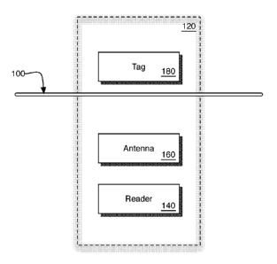
an occupied section of a guideway. Axle counters detect the passing of wheel
flange by the
detection head counting individual wheel axles entering into the occupied
block section. For train
systems where the trains do not have a steel wheel to steel rail interface
(rubber tire systems,
monorails, Maglev, and the like), conventional train detection systems like
track circuits and axle
counters are unreliable or even impossible to apply.
[002] As an alternate to track circuits and axle counters, sometimes train
mounted RFID
transponders and a wayside reader are used to identify the passage of a train
by reading the
identifying information of a train mounted transponder. The wayside reader
evaluates the passing
transponder message to determine a train's movements on the guideway.
[003] For train systems where the trains do not have a steel wheel to steel
rail interface (e.g.,
rubber tire systems, monorails, Maglev, and the like), conventional train
detection systems like
track circuits and axle counters are hard or impossible to apply.
[004] A disadvantage of the existing systems (track circuits and axle
counters) is that they are
connected to the rail in order to provide detection. This feature makes them
susceptible to
electromagnetic interference (EMI) induced into the rail. In particular, the
risk for damage due to
lightning strike which can cause unreliable operation and downstream equipment
damage due to
surge propagation of energy along the rail into galvanically coupled
equipment.
10051 Systems based on detection of transponders mounted on the train and
wayside readers
have the disadvantage that failure of the reader or the transponder can become
dormant and hard
to detect (unless special precautions are put into place) and as such might
affect the safety of the
system (not failsafe).
1
CA 02897564 2016-11-22
BRIEF DESCRIPTION OF THE DRAWINGS
[006] The accompanying drawings, which are incorporated in and constitute a
part of this
specification, illustrate several embodiments and together with the
description, serve to explain
one or more the principles of the invention.
[007] Figure 1 is a top view of an apparatus for detecting the information
about a guideway-
guided vehicle.
[008] Figure 2 illustrates a process flow diagram of some embodiments of an
apparatus for
detecting the information about a guideway-guided vehicle in use.
[009] Figure 3 is a top view of an apparatus for detecting the information
about a guideway-
guided vehicle.
[010] Figure 4 is a side view of an apparatus for detecting the information
about a guideway-
guided vehicle.
[011] Figure 5 is a top view an apparatus for detecting the information about
a guideway-
guided vehicle.
[012] Figure 6 is a functional block diagram of a controller system.
[013] Figure 7 is a side cross-section view of an embodiment.
DESCRIPTION OF EMBODIMENTS
[014] Reference will now be made in detail to embodiments of the invention,
examples of
which are illustrated in the accompanying drawings. Wherever possible, the
same reference
numbers will be used throughout the drawings to refer to the same or like
parts.
[015] In some embodiments, the invention is illustratable by reference to
Figure 1, which
depicts an apparatus for detecting the information about a guideway-guided
vehicle having a
masking component. A guideway 100 separates some of the components of the
radio frequency
identification (RFID) system 120. In some embodiments, the guideway 100 does
not separate
the components of the RFID system 120.
[016] The guideway 100 defines a path of the guideway-guided vehicle (not
shown). Although
a single guideway is shown, in some embodiments, two or more guideways 100
facilitate
transportation of the guideway-guided vehicle. In some embodiments, the
guideway is a rail or a
2
CA 02897564 2016-11-22
groove. In some embodiments, the guideway 100 is load bearing. In some
embodiments, the
guideway comprises iron, steel, or a material suitable for supporting a maglev
or other guideway-
guided vehicle. In some embodiments, the guideway 100 has a guideway
classification (weight)
ranging from 35 to 80 kilograms/meter (kg/m) or from 40 to 60 kg/m or from 55
to 70 kg/m.
[017] The RFID system 120 comprises a reader 140 having a first antenna 160.
In some
embodiments, the reader 140 is connected with the first antenna 160. In some
embodiments, the
reader 140 is in communication with the first antenna 160. A first RFID
transponder 180
transmits, across the path, first RFID transponder specific information, which
is receivable by the
first antenna 160. Suitable RFID systems 120 and component parts thereof are
available from
various vendors.
[018] The RFID transponder 180 is selected from passive RFID transponders,
active RFID
transponders, and battery assisted passive RFID transponders. In some
embodiments, the RFID
transponder 180 uses the electromagnetic energy transmitted, e.g., an
interrogating signal, by the
first antenna 160 for its energy source.
[019] The first RFID transponder 180 has the ability to transmit first RFID
transponder specific
information, such as an individual serial number or information coded to
authenticate the identity
of the first RFID transponder 180. Since some RFID transponders have
individual serial
numbers or other authenticating information, in some embodiments, the RFID
system 120
discriminates between several RFID transponders that might be within the range
of the RFID
reader and in some embodiments reads them substantially simultaneously and/or
continuously.
In some embodiments, the first RFID transponder specific information is an
echo of some or all
of an interrogator signal; data written into the RFID transponder 180; and/or
a product kind.
[020] In some embodiments, the reader 140, first antenna 160, and first RFID
transponder 180
work in a frequency band ranging from 120 kHz to 10 GHz. In some embodiments,
the range is
from 120 to 150 kHz or from 865 to 868 MHz or from 902 to 928 MHz or from 2450
to 5800
MHz or from 3.1 to 10 GHz. For example, in some embodiments, the reader 140,
first antenna
160, and first RFID transponder 180 work in a frequency band approximately
centered about
13.56 MHz or 433 MHz.
[021] The first RFID transponder 180 and the first antenna 160 are fixed
relative to the path and
on opposite sides of the path. In some embodiments, first antenna 160 and
first RFID
3
CA 02897564 2016-11-22
,
,
transponder 180 are separated by a distance ranging from about 0.1 to 200
meter (m). In some
embodiments, the distance ranges from 0.1 to 2 m or from 1 to 2 m or from 2 to
10 m. In some
embodiments, the first RFID transponder 180 and the first antenna 160 are on
opposite sides of
one or more guideways 100. In some embodiments, the connecting path between
the first
antenna 160 and the first RFID transponder 180 slopes vertically above the
guideway 100, or is
perpendicular to the guideway 100.
[022] In some embodiments, the first antenna 160 and first RFID transponder
180 are
independently fixed on or in a structure associated with or in close proximity
to the guideway
structure. For example, in some embodiments, first antenna 160 and first RFID
transponder 180
are independently fixed on a guideway (not necessarily a load bearing
guideway), a sleeper
(railroad ties); a mounting structure associated with a ballast or a mounting
structure associated
with a cess. In some embodiments, the mounting structure associated with a
ballast or cess is
embedded in the ballast and/or cess. Such mounting structures are chosen from
walls, poles,
free-standing structures, and containers. In some embodiments, the first
antenna 160 and first
RFID transponder 180 are embedded in a wall, pole, free-standing structure, or
container.
"Fixed" RFID transponders and/or antennas exclude embodiments, e.g., in which
the first RFID
transponder 180 is fixed on or in a guideway guided vehicle temporarily
stopped or parked in the
vicinity of the antenna 160.
[023] The first antenna 160 and the first RFID transponder 180 are configured
to allow the
masking component of the guideway-guided vehicle to pass between them. For
example, in some
embodiments, the first antenna 160 and the first RFID transponder 180 are
separated in a
horizontal plane along or parallel to or parallel to the path, i.e.,
configured to be side-by-side of
the masking component of the guideway-guided vehicle. For example, in some
embodiments,
the first antenna 160 and the first RFID transponder 180 are separated in a
vertical plane to the
path, i.e., configured to be above and/or below the masking component of the
guideway-guided
vehicle.
[024] Once initiated, the RFID reader 140 is configured to substantially
continuously monitor
the first transponder specific information. Such monitoring allows detecting
the absence of the
masking component of the guideway-guided vehicle, which indicates that the
masking
component of the guideway-guided vehicle is not at the position on the path
between the first
4
CA 02897564 2016-11-22
=
,
,
antenna 160 and the first RFID transponder 180. On the other hand, the
presence of the masking
component of the guideway-guided vehicle between the first RFID transponder
and the first
antenna masks the substantially continuous monitoring of the first RFID
transponder specific
information, which indicates that the masking component of the guideway-guided
vehicle is at
the position on the path between the first antenna 160 and the first RFID
transponder 180.
[025] In some embodiments, the masking component of the guideway-guided
vehicle is
sufficient to reflect and/or scatter and/or absorb the signal bearing the
first RFID transponder
specific information. In some embodiments, the masking component of the
guideway-guided
vehicle is sufficient to interfere with the ability of the first antenna 160
to detect the signal
bearing the RFID transponder specific information. In some embodiments, the
masking
component of the guideway-guided vehicle is a load-bearing part of the
guideway-guided
vehicle. In some embodiments, the masking component of the guideway-guided
vehicle is a
non-load bearing part of the guideway-guided vehicle. In some embodiments, the
guideway-
guided vehicle is selected from locomotives, railroad cars, rail cars,
coaches, and bogies. In some
embodiments, masking components are selected from the under carriages of,
sidewalls of,
wheels of, or flaps on the guideway-guided vehicles.
[026] In some embodiments, the RFID system 120 is configured to determine the
time when a
guideway-guided vehicle traverses between the first RFID transponder 180 and
the first antenna
160.
[027] In some embodiments, the guideway-guided vehicle is part of a group of
two or more
guideway-guided vehicles. In some embodiments, all members of the group
guideway-guided
vehicles have a masking component. In some embodiments, two or more members of
the group
guideway-guided vehicles have a masking component. For example, the first and
last member of
the group of guideway-guided vehicles have the masking component or every nth
member (n=2,
3, ...etc.) of an m member (m >2 x n) group of guideway-guided vehicles have
the masking
component. In such cases, the overall length of the group is determinable from
knowledge about
the frequency or pattern of guideway-guided vehicles having the masking
components. As such,
in some embodiments, the RFID system 120 is configured to determine the number
of guideway-
guided vehicles traversing between the first RFID transponder and the first
antenna. Further
knowledge about the dimension of the guideway-guided vehicles makes it
possible to determine
= CA 02897564 2016-11-22
the length of guideway 100 that is occupied by the at least one guideway-
guided vehicle. As
such, in some embodiments, the RFID system 120 is configured to determine the
occupancy of
the one or more guideway-guided vehicles on the guideway 100.
[028] In some embodiments, the RFID system 120 is configured to determine the
time when
two or more guideway-guided vehicle traverse between the first RFID
transponder 180 and the
first antenna 160.
[029] In some embodiments, the apparatus in use is illustratable by reference
to Figure 2, which
represents a process flow diagram of an apparatus for detecting the
information about a
guideway-guided vehicle in use. As noted above, the RFID system substantially
continuously
monitors a signal bearing the first transponder specific information 210. Such
monitoring allows
detecting the absence of the masking component of the guideway-guided vehicle,
which
indicates that the position is unoccupied, i.e., the masking component of the
guideway-guided
vehicle is not at the position on the path between the first antenna 160 and
the first RFID
transponder 180.
[030] The signal bearing the first transponder specific information is
eventually masked 220.
At this time, it is possible to record the transponder specific information
and optionally the time
230. Typically a masked signal 230 indicates that the position is occupied,
i.e., the masking
component of the guideway-guided vehicle is at the position on the path
between the first
antenna 160 and the first RFID transponder 180.
[031] The signal bearing the first transponder specific information eventually
returns 240. At
this time, it is possible to record the transponder specific information and
optionally the time
250. The RFID system thereafter substantially continuously monitors a signal
bearing the first
transponder specific information 210, which indicates that the system status
is working, which
status is optionally recordable 260.
[032] Optionally, the system is configured to respond to an excessive delay in
the time period
270 between when the signal is masked 220 and when the signal returns 240. For
example, if the
signal return 240 is delayed for an unexpected period of time, which in some
embodiments
ranges from 1-120 seconds or from 10-30 seconds or some other period of time
much longer that
it would take for the masking component to traverse the position, then it is
possible to optionally
record a system status error 280.
6
CA 02897564 2016-11-22
[033] Having knowledge about the time and distance between two or more
guideway-guided
vehicles allows one to determine kinetic parameters like speed. For example,
in some
embodiments, the RFID system 120 is configured to estimate the speed of the
guideway-guided
vehicles traversing between the first RFID transponder 180 and the first
antenna 160 based on
the time period between when two or more guideway-guided vehicle traverse
between the first
RFID transponder 180 and the first antenna 160.
[034] In some embodiments, the RFID system 120 is configured to communicate
information
to a processor (not shown). In some embodiments, the communication is
wireless. In some
embodiments, the communication is wired. In some embodiments, the processor is
a zone
controller.
[035] In some embodiments, the information is chosen from the absence of a
guideway-guided
vehicle between the first RFID transponder 180 and the first antenna 160; the
presence of a
guideway-guided vehicle between the first RFID transponder 180 and the first
antenna 160; the
time when at least one guideway-guided vehicle passes between the first RFID
transponder 180
and the first antenna 160; the number of guideway-guided vehicles passing
between the first
RFID transponder 180 and the first antenna 160 for a time period; kinetic
information (including
speed and the like) regarding at least one guideway-guided vehicle passing
between the first
RFID transponder 180 and the first antenna 160 for a time period; the
occupancy on the
guideway 100 of the at least one guideway-guided vehicle passing between the
first RFID
transponder 180 and the first antenna 160 for a time period, and the system
status.
[036] In some embodiments, the RFID system 110 further comprises an additional
RFID
transponder and optionally an additional antenna. In such embodiments,
additional information
about the guideway-guided vehicle is obtainable.
[037] In some embodiments, the invention is illustratable by reference to
Figure 3, which
depicts an apparatus for detecting the information about a guideway-guided
vehicle having a
masking component. A guideway 300 separates some of the RFID system 320. In
some
embodiments, guideways 300,310 separate some of the RFID system 320. In some
embodiments, no guideways 300,310 separate the RFID system 320, such as in a
vertical
arrangement of an antenna-transponder pair.
7
CA 02897564 2016-11-22
[038] In Figure 3, the RFID system 320 comprises an RFID reader 340, a first
antenna 360 for
receiving the first RFID transponder specific information, and a second
antenna 370 for
receiving the second RFID transponder specific information. The RFID system
320 comprises
not only a first RFID transponder 380 for transmitting, across the path, first
RFID transponder
specific information but the RFID system 320 further comprises a second RFID
transponder 390
for transmitting, across the path, second RFID transponder specific
information. The first RFID
transponder 380 and the first antenna 360 are fixed relative to the path and
on opposite sides of
the path. The second RFID transponder 390 and the second antenna 370 are fixed
relative to the
path and on opposite sides of the path. The RFID reader 340 is configured to
substantially
continuously monitor both the first transponder specific information from the
first RFID
transponder 380 and the second transponder specific information from the
second RFID
transponder 390. The presence of the masking component of the guideway-guided
vehicle
between the first RFID transponder 380 and the first antenna 360 masks the
substantially
continuous monitoring of the first RFID transponder specific information, and
the presence of
the masking component of the guideway-guided vehicle between the second RFID
transponder
390 and the second antenna 370 masks the substantially continuous monitoring
of the second
RFID transponder specific information.
[039] An additional antenna-transponder pair makes it possible to provide a
safeguard should
the first fail. The additional antenna-transponder pair operates in an
analogous manner to the first
antenna-transponder pair.
[040] As noted above, monitoring allows detecting the presence or absence of
the masking
component of the guideway-guided vehicle, which indicates that the masking
component of the
guideway-guided vehicle is or is not at the position on the path between the
first antenna 360 and
the first RFID transponder 380 and/or the second antenna 370 and the second
RFID transponder
390.
[041] In some embodiments, the first RFID transponder 380 is separated from
the second RFID
transponder 390 by a distance, along or parallel to the path, such that the
masking component of
the guideway-guided vehicle is at the position on the path between the first
antenna 360 and the
first RFID transponder 380 but not at the position on the path between the
second antenna 370
and the second RFID transponder 390 and vice versa. In some embodiments, the
first RFID
8
CA 02897564 2016-11-22
transponder 380 is separated from the second RFID transponder 390 by a
distance, along or
parallel to the path, of at least 1 m. In some embodiments, the distance
ranges from 1 to 30 m or
from 2 to 20 m or 10 to 15 m or from 3 to 5 m.
[042] In some embodiments, as in Figure 3, the RFID system 320 further
comprises a switch
350 configured to alternate monitoring between the first transponder specific
information via the
first antenna 360 and the second transponder specific information via the
second antenna 370.
Notwithstanding the alternating, the monitoring is substantially continuous.
In some
embodiments, the monitoring between the first transponder specific information
via the first
antenna 360 and the second transponder specific information via the second
antenna 370
alternates at symmetric periods. In some embodiments, the monitoring between
the first
transponder specific information via the first antenna 360 and the second
transponder specific
information via the second antenna 370 alternates at asymmetric periods. In
some embodiments,
switching period is random. .
[043] In accordance with at least some embodiments, by continuous alternating
of the reading
of the first transponder and the second transponder via the RF switch and the
first and second
antenna, the health status of the system is continually verified and dormant
failures detected. As
such the apparatus is able to achieve a Safety Integrity Level (SIL) 4 as no
dormant failures of
the system remain undetected. SIL 4 is based on International Electrotechnical
Commission's
(IEC) standard IEC 61508, in at least one embodiment. SIL level 4 means the
probability of
failure per hour ranges from 10-8 to 10-9.
[044] In at least some embodiments, RFID system 320 controls switch 350 to
alternate
according to a predetermined alternation pattern between monitoring first
antenna 360 and
second antenna 370. In at least some embodiments, the predetermined
alternation pattern
allocates monitoring of antennas according to a round robin scheduling
pattern. In at least some
embodiments, the predetermined alternation pattern allocates monitoring of
antenna according to
a random distribution scheduling pattern. In at least some embodiments, the
predetermined
alternation pattern allocates monitoring of antenna according to an unbalanced
distribution
pattern in which one antenna is monitored more frequently than another
antenna. In at least
some embodiments, more antennas are used in conjunction with RFID system 320
and the
predetermined alternation pattern is applied to the antennas used. In at least
some embodiments,
9
= CA 02897564 2016-11-22
more antennas are used in conjunction with RFID system 320 and the
predetermined alternation
pattern is applied to a subset of the antennas used. In at least one
embodiment, the switch 350
alternates between monitoring the first antenna 360 and second antenna 370
according to a given
pattern of A, B, B, A, B, A, A, B, A, B, B, A ... in which A corresponds to a
period of
monitoring the first antenna 360 and B corresponds to a period of monitoring
the second
antenna 370.
[045] For example, each transponder-antenna pair works in a manner previously
explained in
reference to Figures 1-2. Referring to Figure 2, if "1" indicates a signal
(unmasked) and "0"
indicates a masked signal, then there are four possible states for the first
transponder-antenna
pair ("11") and the second transponder-antenna pair (T2).
[046] Table 1. Transponder states
[047] T1 12
[048] 1 1 indicates an absence of a masking component at
positions of Tl-T2
[049] 0 1 presence at T1, absence at T2
[050] 1 0 absence at T1, presence at T2
[051] 0 0 presence at T1 -T2, possible in some
embodiments, but not this one
[052] More transponder-antenna pairs are possible in some embodiments.
1053] In at least a given embodiment, use of a single RF switch (as in switch
350 of FIG. 3)
enables functionality related to a self checking mechanism for determining
fail safe or vitality of
the system. In accordance with the given embodiment, RFID reader 340 receives
the
transponder specific information from the corresponding antenna 360, 370 via
RF switch 350 in
accordance with the predetermined alternation pattern of monitoring. RF Switch
350 alternates
between continuously alternating monitoring first antenna 360 and second
antenna 370. In this
manner, transponder specific information received by RFID reader 340 is not
older than the last
alternation of monitoring performed by RF switch 350. RFID reader 340 does not
receive stale
information or data (i.e., older than the last received information or data)
from switch 350
regarding a monitored antenna. In at least some embodiments, the received
transponder specific
information includes time and/or date stamp information indicating a time
and/or date related to
the generation and/or transmission of the transponder specific information.
CA 02897564 2016-11-22
[054] In accordance with the given embodiment, RFID system 320 is able to
verify fail safe
operation of the Apparatus by comparing the changing received transponder
specific information
from switch 350 due to the predetermined alternation pattern of monitoring.
That is, because
switch 350 alternates between monitoring first antenna 360 and the first
transponder 380 and
second antenna 370 and the sedond transponder 370, the data transmitted from
switch 350 to
RFID reader 340 changes in accordance with the alternation of monitoring. If
the data received
by RFID reader 340 does not change, then RFID system 320 is able to determine
that a failure
has occurred, in at least some embodiments.
[055] Continuing with the given embodiment, a vehicle moving on the guideway
300 from the
bottom of the page upward first encounters first antenna 360 paired with first
transponder 380
and a masking component of the vehicle interrupts the path between the pair
preventing switch
350 from receiving transponder specific information from first antenna 360.
However, the path
between the second antenna 370 and second transponder 390 is uninterrupted by
the vehicle and
switch 350 receives transponder specific information from second antenna 370
during the period
in which the switch monitors the second antenna. During this period (where the
path between
360 and 380 is interrupted), system 320 is able to determine that second
antenna 370 is operating
normally and that first antenna 360 is not providing transponder specific
information which is
indicative of either a failure of first antenna 360 or a vehicle on guideway
300 interrupting the
path between the first antenna and the first transponder. After the vehicle
transitions beyond
interrupting the path between first antenna 360 and first transponder 380,
switch 350 receives
transponder specific information which indicates that the first antenna is
operating normally.
[056] After the vehicle transitions further up the guideway 300 (further up
the page), the
vehicle encounters second antenna 370 paired with second transponder 390 and
the masking
component of the vehicle interrupts the path between the pair preventing
switch 350 from
receiving transponder specific information from the second antenna. However,
as in the above
period during blockage of the path between the second antenna and second
transponder, the path
between the first antenna 360 and first transponder 380 is uninterrupted by
the vehicle and
switch 350 receives transponder specific information from first antenna 360
during the period in
which the switch monitors the first antenna. During this period, system 320 is
able to determine
that first antenna 360 is operating normally and that second antenna 370 is
not providing
transponder specific information which is indicative of either a failure of
second antenna 370 or
11
CA 02897564 2016-11-22
=
a vehicle on guideway 300 interrupting the path between the second antenna and
the second
transponder. After the vehicle transitions beyond interrupting the path
between second antenna
370 and second transponder 390, switch 350 receives transponder specific
information which
indicates that the second antenna is operating normally. In this manner, fail
safe SIL 4 operation
of the system is ensured, in at least some embodiments.
[057] In at least some embodiments, a predetermined timeout period is used to
determine
whether an interruption of a path between a transponder-antenna pair is
indicative of a failure of
the system. If the path is interrupted for a time period greater than the
predetermined timeout
period, a system failure is determined to have occurred and an alert or other
indication is
generated. In at least some embodiments, the indication is transmitted to a
system
communicably connected with system 320. In at least some embodiments, the
indication is
stored local to system 320.
[058] Additionally, in at least some embodiments, use of a single switch 350
reduces the
overall cost of the system in addition to the foregoing advantages.
[059] In some embodiments, the RFID system 320 is configured to determine the
direction of
travel of the guideway-guided vehicle based on the order in which (a) the
substantially
continuous monitoring of the first RFID transponder specific information is
masked and (b) the
substantially continuous monitoring of the second RFID transponder specific
information is
masked. In this case, the guideway-guided vehicle is traveling in the
direction in which the
masking occurs. For example, assume masking occurs in the following order in
time (t = time,
arbitrary units).
1060] Table 2. Transponder states as a function of increasing time.
[061] t T1 T2
[062] 1 1 1 absence at positions of Tl-T2
[063] 2 0 1 presence at T1, absence at T2
[064] 3 1 0 absence at T1, presence at T2
[065] Based on the data in Table 2, the guideway-guided vehicle is moving from
the position of
T1 towards the position of T2.
12
CA 02897564 2016-11-22
10661 For example, if the first RFID transponder 380 is separated from the
second RFID
transponder 390 by a distance, along or parallel to the path, such that the
masking component of
the guideway-guided vehicle is at the position on the path between the first
antenna 360 and the
first RFID transponder 380 but not at the position on the path between the
second antenna 370
and the second RFID transponder 390, then the RFID system 320 has the ability
to self-check
and to determine additional information regarding the one or more guideway-
guided vehicles.
Referring to Table 1, although the 0,0 embodiment (T1,T2) is possible in some
embodiments, in
some embodiments like this one, the 0,0 state is not allowed by the relative
fixed positions of the
first and second transponder-antenna pairs. In this embodiment, if this state
were to occur, then
the system would be in error, such as a power outage. Such system status is
recordable.
10671 An example of such an embodiment is illustratable in Figure 4, which
depicts an
apparatus for detecting the information about a coach 417 or 418 having a
masking component
412 or 413 or 414. In this embodiment, the masking components 412-414
correspond to the
wheels of the coach 417 or 418. Guideways 400,410 define a path for the
coaches 417 & 418 and
separate some of the RFID system 420, which comprises RFID reader 440 in
communication
with a first antenna 460 and a second antenna 470 (outside the guideways
400,410 and on the
side with guideway 410), a first transponder 480, and a second transponder 490
(outside the
guideways 400,410 on side with guideway 400). The first transponder 480 and a
second
transponder 490 are fixed at a position such that the masking components 412-
414 of the boxcars
417-418 are at the position on the path between the first antenna 460 and the
first RFID
transponder 480 but not at the position on the path between the second antenna
470 and the
second RFID transponder 490. Referring to Table 1, although the 0,0 embodiment
(T1,T2) is
possible in some embodiments, in this embodiment, the 0,0 state is not allowed
by the relative
fixed positions of the first and second transponder-antenna pairs. In this
embodiment, if the 0,0-
state were to occur, then the system would be in error and determinable by
if...then logic testing.
Such a system status is recordable.
[068] With reference to Figure 3, in some embodiments, the RFID system 320 is
configured to
determine the system status based on (a) the substantially continuous
monitoring of the first
RFID transponder specific information and (b) the substantially continuous
monitoring of the
second RFID transponder specific information. For example, if the masking
component of the
guideway-guided vehicle is at the position on the path between the first
antenna 360 and the first
13
CA 02897564 2016-11-22
=
RFID transponder 380, the monitoring is configured to determine whether or not
the masking
component of the guideway-guided vehicle thereafter arrives at the position on
the path between
the second antenna 370 and the second RFID transponder 390 within a false
positive monitoring
period. If the false monitoring period ends without masking at the position on
the path between
the second antenna 370 and the second RFID transponder 390, then the RFID
system 320 is
configured to make a false positive determination. In this way, e.g., the RFID
system 320 has
the ability to self-check its status. Such a status is recordable.
[069] The false positive monitoring period is of a sufficient duration for the
guideway-guided
vehicle to traverse the distance of separation along or parallel to the path
between the first RFID
transponder 380 and the second RFID transponder 390. In some embodiments, the
false positive
monitoring period depends on one or more of several factors such as the
separation distance, the
speed of the guideway-guided vehicles, and the like. In some embodiments, the
false positive
monitoring period ranges from 1-120 seconds or from 10-30 seconds.
[070] In some embodiments, the apparatus is self-checking, allowing for the
detection of
failures and/or is not connected to the guideway thus decreasing problems
associated with
EMI/EMC (electromagnetic interference / electromagnetic compatibility) that a
system
connected to the guideway would experience.
[071] In some embodiments, the RFID system 320 is configured to communicate
information
with a processor 355. In some embodiments, the communication is wireless. In
some
embodiments, the communication is wired. In some embodiments, the processor is
a zone
controller. The processor noted herein is useable with any embodiment,
including those
associated with Figure 3.
[072] FIG. 7 is a side cross-section view of the Figure 3 embodiment. RFID
reader 340 is
communicatively connected with RF switch 350. RF switch 350 is communicatively
connected
with first and second antennas 360, 370. First and second antennas 360/370 are
in
communication with a corresponding first and second transponder 380, 390.
1073] In some embodiments, the information is chosen from the same types of
information
noted above for the embodiments of Figures 1-2. In addition to that
information, additional
information includes the direction of travel of the guideway-guided vehicle
and the system status
14
CA 02897564 2016-11-22
of the RFID system 320. Because position and direction are determinable, more
kinetic
information is determinable, e.g., the velocity and the like of the guideway-
guided vehicle.
[074] In some embodiments, the invention is illustratable by reference to
Figure 5, which
depicts an apparatus for detecting the information about a guideway-guided
vehicle 517 having a
masking component (not shown). Guideways 500,510 guide the guideway-guided
vehicle 517.
A guideway 500 separates some components of the RFID system 520. The RFID
system 520
comprises an RFID reader 540, a first antenna 560 for receiving the first RFID
transponder
specific information and optionally (not shown) a second antenna for receiving
the second RFID
transponder specific information. The RFID system 520 comprises a first RFID
transponder 580
for transmitting, across the path, first RFID transponder specific information
and optionally (not
shown) a second RFID transponder for transmitting, across the path, second
RFID transponder
specific information. The first RFID transponder 580 and the first antenna 560
are fixed relative
to the path and on opposite sides of the path, and the optional (not shown)
second RFID
transponder and the second antenna are fixed relative to the path and on
opposite sides of the
path as noted above. The RFID reader 540 is configured to substantially
continuously monitor
the first transponder specific information from the first RFID transponder 580
and optionally the
second transponder specific information from the second RFID transponder as
noted above. The
presence of the masking component of the guideway-guided vehicle between the
first RFID
transponder 580 and the first antenna 560 masks the substantially continuous
monitoring of the
first RFID transponder specific information, and optionally (not shown) the
presence of the
masking component of the guideway-guided vehicle between the second RFID
transponder and
the second antenna masks the substantially continuous monitoring of the second
RFID
transponder specific information.
[075] In Figure 5, the RFID system 520 further comprises a switch 550
configured to alternate
monitoring between the first transponder specific information via the first
antenna 560 and
optionally (not shown and when present) the second transponder specific
information via the
second antenna. The apparatus works like the one described with reference to
Figures 1-4.
[076] In Figure 5, the RFID system 520 is configured to receive mounted RFID
transponder
specific information from a guideway-guided vehicle having a mounted RFID
transponder 585
for transmitting the mounted RFID transponder specific information. The
mounted RFID
CA 02897564 2016-11-22
transponder 585 is any RFID transponder, such as those mentioned above. In
some
embodiments, the mounted RFID transponder 585 is configured to transmit the
mounted RFID
transponder specific information concerning the identity of the guideway-
guided vehicle on
which the mounted RFID transponder is mounted. The mounted RFID transponder
585 is
mountable in suitable locations of the guideway-guided vehicle 517, and in
some embodiments is
mounted on the axles of the wheels, on the containment structure, or in the
compartment of the
guideway-guided vehicle 517.
[077] In some embodiments, the RFID system 520 is configured to communicate
information
with a processor 555, such as a zone control center. The information includes,
in some
embodiments, the mounted RFID transponder specific information, e.g.,
concerning the identity
of the guideway-guided vehicle on which the mounted RFID transponder is
mounted.
[078] Of course, the embodiments of Figure 5 would work with embodiments
having a single
pair antenna-transponder and embodiments having multiple pairs of antennas-
transponders. Of
course, the embodiments of Figure 5 would also work with other embodiments
disclosed herein.
10791 In some embodiments, the apparatus not only vitally detects the guideway-
guided vehicle
entering/exiting the guideway section but it also determines, e.g., the
identity of the guideway-
guided vehicle entering / exiting the guideway section by reading the mounted
RFID transponder
585.
[080] In some embodiments, the apparatus make it possible to detect vital
information
regarding the guideway-guided vehicle using non-vital RFID equipment.
[081] In some embodiments, the apparatus make it possible to detect signals
suitable for
railway signaling for guideway-guided vehicle detection system.
[082] In some embodiments, the apparatus make it possible to detect safety-
critical absence
detection of metallic or non-metallic objects associated with a detectable
guideway-guided
vehicle.
[083] In some embodiments, a method of detecting information about a guideway-
guided
vehicle having a masking component is provided. Any transponder specific
information
disclosed herein is detectable. The following provides examples of various
embodiments.
16
CA 02897564 2016-11-22
[084] In some embodiments, the guideway-guided vehicle is configured to follow
a path of a
guideway. In some embodiments, the method substantially continuously monitors,
with a first
antenna connected to or in communication with a first RFID reader, first
transponder specific
information transmitted from a first RFID transponder. As noted above, the
presence of the
masking component of the guideway-guided vehicle between the first RFID
transponder and the
first antenna masks the substantially continuous monitoring of the first RFID
transponder
specific information. Also, as noted above, the first RFID transponder and the
first antenna are
fixed relative to the path and on opposite sides of the path.
[085] In some embodiments, a second antenna and a second transponder are
useable. For
example, in some embodiments, the method further comprises substantially
continuously
monitoring, with a second antenna connected to or in communication with an
RFID reader,
second transponder specific information transmitted from a second RFID
transponder. Again,
the presence of the masking component of the guideway-guided vehicle between
the second
RFID transponder and the second antenna masks the substantially continuous
monitoring of the
second RFID transponder specific information. Also, the second RFID
transponder and the
second antenna are fixed relative to the path and on opposite sides of the
path.
[086] As noted above, in some embodiments the first RFID transponder is
separated from the
second RFID transponder by a distance, along or parallel to the path, such
that the presence of
the masking component of the guideway-guided vehicle between the first RFID
transponder and
the first antenna sufficient to mask the substantially continuous monitoring
of the first RFID
transponder specific information does not occur at the same time of masking
the substantially
continuous monitoring of the second RFID transponder specific information.
[087] In some embodiments, substantially continuous monitoring of the first
transponder
specific information alternates with the substantially continuous monitoring
the second
transponder specific information.
10881 In some embodiments, the method further comprises determining the
direction of travel
of the guideway-guided vehicle based on the order in time in which (a) the
substantially
continuous monitoring of the first RFID transponder specific information is
masked and (b) the
substantially continuous monitoring of the second RFID transponder specific
information is
masked.
17
CA 02897564 2016-11-22
=
[089] In some embodiments, the method further comprises determining the system
status based
on the time in which (a) the substantially continuous monitoring of the first
RFID transponder
specific information is masked and the time in which (b) the substantially
continuous monitoring
of the second RFID transponder specific information is masked.
[090] In some embodiments, the method further comprising monitoring, with the
antenna
connected to or in communication with the first RFID reader, mounted RFID
transponder
specific information from a guideway-guided vehicle having a mounted RFID
transponder.
[091] In some embodiments, the method further comprises communicating the
information to a
processor.
[092] Figure 6 is a block diagram of a controller system 600 usable for
implementing a method
associated with the apparatus, such as those associated with Figures 1-5 and
other embodiments
vide infra, in accordance with one or more embodiments. In at least some
embodiments, system
600 is usable as at least a portion of reader 140 (FIG. 1). System 600
includes a hardware
processor 602 and a non-transitory, computer readable storage medium 604
encoded with, i.e.,
storing, the computer program code 606, i.e., a set of executable
instructions. The processor 602
is electrically coupled to the computer readable storage medium 604 via a bus
608 or other
suitable mechanism. The processor 602 is configured to execute the computer
program code 606
encoded in the computer readable storage medium 604 in order to cause system
600 to be usable
for performing a portion or all of the operations as depicted in relation to
the uses of the
apparatus disclosed herein, including those in Figures 1-5.
[093] In some embodiments, the processor 602 is a central processing unit
(CPU), a multi-
processor, a distributed processing system, an application specific integrated
circuit (ASIC),
and/or a suitable processing unit.
[094] In some embodiments, the computer readable storage medium 604 is an
electronic,
magnetic, optical, electromagnetic, infrared, and/or a semiconductor system
(or apparatus or
device). For example, the computer readable storage medium 604 includes a
semiconductor or
solid-state memory, a magnetic tape, a removable computer diskette, a random
access memory
(RAM), a read-only memory (ROM), a rigid magnetic disk, and/or an optical
disk. In some
embodiments using optical disks, the computer readable storage medium 604
includes a compact
18
CA 02897564 2016-11-22
=
disk-read only memory (CD-ROM), a compact disk-read/write (CD-R/W), and/or a
digital video
disc (DVD).
[095] In some embodiments, the storage medium 604 stores the computer program
code 606
configured to cause system 600 to perform a method associated with the
apparatus disclosed
herein, including those associated with Figures 1-5. In some embodiments, the
storage medium
604 also stores information and/or data needed for performing a method or
generated during
performing the method, such as temporary variables, lookup tables, and/or a
set of executable
instructions to perform the operation associated with the disclosed apparatus,
including those of
Figures 1-5.
[096] System 600 includes, in at least some embodiments, an input/output
interface 628. The
input/output interface 628 is coupled to external circuitry. In at least some
embodiments,
input/output interface 628 receives data and/or information from antenna 160
(FIG. 1).
[097] In at least some embodiments, system 600 also includes an optional
network interface
630 coupled to the processor 602. The network interface 630 allows system 600
to communicate
with a network 632, to which one or more other computer systems are connected.
Network
interface 630 includes wireless network interfaces such as BLUETOOTH, WIFI,
WIMAX,
GPRS, or WCDMA; or wired network interface such as ETHERNET, USB, or IEEE-
1394. In
some embodiments, the method associated with the apparatus, including those of
Figures 1-5 are
implemented in two or more system, and information and/or data are exchanged
between
different systems 600 via the network 632.
[098] System 600 is configured to receive information related to a type of
process through I/0
628. The information is transferred to processor 602 via bus 608 to determine
at least vehicle
detection based on an RFID system.
[099] In some embodiments, a method of making an apparatus for detecting the
information
about a guideway-guided vehicle having a masking component, the guideway-
guided vehicle
configured to follow a path of a guideway is provided. Any apparatus disclosed
herein is
makeable. The following provides examples of various embodiments.
101001 In some embodiments, the apparatus is made by fixing a first RFID
transponder and a
first antenna relative to the path and on opposite sides of the path. As noted
above, the first RFID
19
= CA 02897564 2016-11-22
transponder is for transmitting, across the path, first RFID transponder
specific information, the
first antenna is configured for receiving the first RFID transponder specific
information, the first
antenna is connect to a first RFID reader which is configured to substantially
continuously
monitor the first transponder specific information, and the presence of the
masking component of
the guideway-guided vehicle between the first RFID transponder and the first
antenna masks the
substantially continuous monitoring of the first RFID transponder specific
information.
[0101] In some embodiments, the invention comprises an apparatus for detecting
the information
about a guideway-guided vehicle having a masking component, a guideway
defining a path of
the guideway-guided vehicle, comprising an RFID system; wherein the RFID
system comprises:
a first RFID transponder for transmitting, across the path, first RFID
transponder specific
information; an RFID reader comprising a first antenna for receiving the first
RFID transponder
specific information; and wherein the first RFID transponder and the first
antenna are fixed
relative to the path and on opposite sides of the path; wherein the RFID
reader is configured to
substantially continuously monitor the first transponder specific information;
and wherein the
presence of the masking component of the guideway-guided vehicle between the
first RFID
transponder and the first antenna masks the substantially continuous
monitoring of the first RFID
transponder specific information.