Note: Descriptions are shown in the official language in which they were submitted.
CA 02897661 2015-07-15
ACCESS DOOR
Technical Field
[0001] Some embodiments of the present invention relate to access doors for
use in providing
access to functional building components behind finished surfaces such as
walls or ceilings.
Some embodiments of the present invention relate to methods of using such
access doors.
Background
[0002] In building construction, it is often necessary to provide ready access
to spaces containing
functional building elements behind finished surfaces such as walls and
ceilings. For example,
access may be required to reach plumbing fixtures, valves on water lines,
meters on gas lines,
electrical fixtures, switches, circuit breakers, or the like positioned behind
a finished building
surface such as a wall or ceiling.
[0003] Typically, access is accomplished by providing an opening in the
finished surface and
inserting an access panel that can be removed or an access door that can be
opened in the
opening. The access panel or access door provides access to the space behind
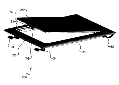
the opening. In
situations where the access panel or access door is regularly viewed by
persons within the
building, the access panel or access door may also provide an aesthetically
pleasing look
consistent with the finished surface.
[0004] To provide access to the space behind the opening, an access panel must
be removed.
After the necessary work has been completed, the access panel must be placed
back in the
opening. In contrast, the door of an access door can simply be opened to
provide access to the
space. After the necessary work has been completed, the access door can be
secured in the
closed position.
[0005] A typical access door has a frame that is installed in the opening of a
finished
construction surface. The frame supports a door mounted thereon with hinges,
so that the door
can be moved between a closed position covering the opening and an open
position allowing
access through the opening. A typical access door also includes a latch or
lock mechanism,
CA 02897661 2015-07-15
which allows the door to be secured in the closed position.
[0006] Installation of typical access doors is slow and cumbersome. Some
access doors are
installed using screws or nails fastened through apertures provided in an
internal flange of the
frame. In some cases, adhesives and/or caulking may be used to secure the
access door in place.
Furthermore, once installed, typical access doors cannot be readily removed.
This presents
additional difficulties, for example if the construction surface in which the
access door is located
needs to be refinished.
[0007] The foregoing examples of the related art and limitations related
thereto are intended to
be illustrative and not exclusive. Other limitations of the related art will
become apparent to
those of skill in the art upon a reading of the specification and a study of
the drawings.
Summary
[0008] The following embodiments and aspects thereof are described and
illustrated in
conjunction with systems, tools and methods which are meant to be exemplary
and illustrative,
not limiting in scope. In various embodiments, one or more of the above-
described problems
have been reduced or eliminated, while other embodiments are directed to other
improvements.
[0009] One aspect of the invention provides a clip-in access door for covering
an opening in a
construction surface. The access door has a frame for mounting in the opening,
and a door
mounted on the frame. The door is moveable between a closed position covering
the opening
and an open position allowing at least partial access through the opening. A
plurality of clips are
mounted on the frame for securing the frame in the opening. The clips along at
least one edge of
the frame are rotatable clips that are rotatable between an insert position
allowing the frame to be
inserted fully into the opening without substantial interference by the
rotatable clips and a lock
position securing the frame in the opening. In some embodiments, the rotatable
clips have a
curved clamping portion.
[00101 A further aspect of the invention provides a clip-in access door for
covering an opening
2
CA 02897661 2015-07-15
in a construction surface. The access door has a frame for mounting in the
opening, and a door
mounted on the frame. The door is moveable between a closed position covering
the opening
and an open position allowing at least partial access through the opening. At
least two clips are
mounted on the frame for securing the frame in the opening. A first one of the
at least two clips
is mounted on a first edge of the frame and is a fixed clip. A second one of
the at least two clips
is mounted on a second edge of the frame opposite the first edge and is a
rotatable clip that is
rotatable between an insert position allowing the frame to be inserted fully
into the opening
without substantial interference by the rotatable clips and a lock position
securing the frame in
the opening. In some embodiments, the rotatable clip has a curved clamping
portion.
[0011] A further aspect of the invention provides a method of installing a
clip-in access door in
an opening in a construction surface. A first edge of a frame of the access
door bearing at least
one clip is inserted over a clamping surface of a corresponding first edge of
the opening so that
the clip engages with the clamping surface. A second edge of the frame of the
access door
bearing at least one rotatable clip is inserted over a clamping surface on a
corresponding second
edge of the opening, with the rotatable clip being rotated to an insert
position. After the access
door is positioned, the rotatable clip is rotated from the insert position to
a lock position so that
the rotatable clip engages a clamping surface on the second edge of the
opening to secure the
clip-in access door in an installed position.
[0012] In addition to the exemplary aspects and embodiments described above,
further aspects
and embodiments will become apparent by reference to the drawings and by study
of the
following detailed descriptions.
Brief Description of the Drawings
[0013] Exemplary embodiments are illustrated in referenced figures of the
drawings. It is
intended that the embodiments and figures disclosed herein are to be
considered illustrative
rather than restrictive.
[0014] Figure lA is a front view of a schematic representation of a clip-in
access door according
3
CA 02897661 2015-07-15
to one example embodiment.
[0015] Figure 1B is a perspective view of a clip-in access door according to
an example
embodiment with the door in the open position.
[0016] Figure 1C is a rear view of an example embodiment of a clip-in access
door with the
rotatable clips in a locked position.
[0017] Figure 2 is a cross-sectional view of an example embodiment of a clip-
in access door
installed in an opening of a construction surface.
[0018] Figure 3 is a side view of an example embodiment of a fixed clip for
use in some
embodiments.
[0019] Figure 4 is a side view of a second example embodiment of a fixed clip
for use in some
embodiments.
[0020] Figure 5 is a side view of an example embodiment of a rotatable clip
for use in some
embodiments.
[0021] Figure 6 is a schematic diagram showing an example embodiment of a
rotatable clip in
exemplary insert and lock configurations.
[0022] Figure 7 is a cross-sectional view of an example embodiment of a clip-
in access door
showing details of the hinges used to secure the door to the frame.
Description
[0023] Throughout the following description specific details are set forth in
order to provide a
more thorough understanding to persons skilled in the art. However, well known
elements may
not have been shown or described in detail to avoid unnecessarily obscuring
the disclosure.
4
CA 02897661 2015-07-15
Accordingly, the description and drawings are to be regarded in an
illustrative, rather than a
restrictive, sense.
[0024] As used in this specification, the term "inwardly" means in a direction
towards the centre
of the clip-in access door. The term "outwardly" means in a direction away
from the centre of
the clip-in access door.
[0025] With reference to Figure 1A, an example embodiment of a clip-in access
door 20 is
schematically illustrated. Clip-in access door 20 has a frame 22 and a door
24. Door 24 is
secured to frame 22 via hinges 26, which allow door 24 to be moved to an open
position with
respect to frame 22 to provide access through an opening 29 in a construction
surface 30. A
securing mechanism 28 is provided to releasably hold door 24 in a closed
configuration with
respect to frame 22, covering the opening 29 in a construction surface 30.
[0026] In order to secure frame 22 in an opening 29 in a construction surface
30 (Figure 2), a
plurality of clips are provided on frame 22. The clips are configured so that,
in the installed
configuration, a portion of the construction supporting construction surface
30, or a portion of
construction surface 30 itself, referred to herein as a clamping surface 33,
interposes the clips
and frame 22, so that the clips secure frame 22 in place in opening 29.
[0027] As best seen in the embodiment illustrated in Figures 1B and 1C in
which elements that
correspond with elements shown in the embodiment of Figure 1 A are shown with
the same
reference numeral, mounting flanges 31 are provided on the upper and lower
edges of frame 22
to support frame 22 in the vertical direction. Mounting flanges 31 project
generally away from
frame 22 horizontally into opening 29, so that mounting flanges 31 can contact
the upper and
lower edges of opening 29 to secure frame 22 in the vertical direction.
[0028] To facilitate installation of access door 20, the clips along at least
one edge of access door
20 are rotatable between an insert position, wherein the clips do not project
outwardly to such an
extent that they interfere appreciably with a user sliding frame 22 into an
installed position in
opening 29, and a lock position, wherein a clamping surface 33 interposes the
clip and frame 22
5
CA 02897661 2015-07-15
to hold frame 22 in the installed position. The insert and lock positions are
described in greater
detail with reference to Figure 6 below.
[0029] In the illustrated embodiment, four clips are provided on frame 22 to
hold frame 22 in the
installed position. A pair of rotatable clips 32 are provided proximate
adjacent corners 23A, 23B
of frame 22, and a pair of fixed clips 34 are provided proximate the other two
corners 23C, 23D
of frame 22. The adjacent corners 23A, 23B are on a first edge 21A of frame
22. The adjacent
corners 23C, 23D are on a second edge 21C of frame 22, opposite to the first
edge 21A. Fixed
clips 34 have a fixed position (i.e. cannot be rotated). Rotatable clips 32
are rotatable about an
axis perpendicular to the plane of frame 22.
[0030] With reference to Figure 3, in the illustrated embodiment, fixed clips
34 have a base 36
that can be secured to frame 22, a spacing portion 38 that extends generally
perpendicularly from
the base 36, and a clamping portion 40 that engages with the clamping surface
33 of the
construction element to which clip 34 is secured, the clamping portion 40
extending generally
perpendicularly or at a slightly acute angle from spacing portion 38. Clamping
portion 40
projects outwardly from base 36, to receive a clamping surface 33 of a
construction element
between frame 22 and clamping portion 40. In the illustrated embodiment, the
outer end of
clamping portion 40 is provided with a deflected tip 42, which can facilitate
insertion of a
construction element between clip 34 and frame 22. In the illustrated
embodiment, deflected tip
42 is bent in a direction away from base 36, which may make it easier for a
user to slide clip 34
over clamping surface 33.
[0031] Any suitable clip that can be used to secure frame 22 to a construction
element forming
or supporting part of construction surface 30 may be used in place of clip 34.
For example, with
reference to Figure 4, in an alternative embodiment in which parts that
perform a similar function
have been illustrated with reference numerals incremented by 100, fixed clip
134 has a base 136
with an aperture for receiving a threaded fastener 137 that is used to secure
fixed clip 134 in
place on frame 22. Fixed clip 134 also has a spacing portion 138 that is
relatively shorter than
spacing portion 38 of fixed clip 34, since fastener 137 spaces fixed clip 134
a small distance
away from frame 22 in use. A clamping portion 140 extends outwardly from
spacing portion
6
CA 02897661 2015-07-15
138 so that a clamping surface 33 can be received and held between clamping
portion 140 and
frame 22. Clamping portion 140 also includes a deflected tip 142, which may
facilitate insertion
of clamping surface 33 into fixed clip 134 in the same manner as described for
deflected tip 42.
In some embodiments, deflected tip 42 or deflected tip 142 is omitted.
[0032] In some embodiments, one or both of fixed clips 34 could be replaced by
rotatable clips
such as clips 32. In some embodiments, a single fixed clip 34 could be used on
edge 21C of
frame 22 to hold access door 20 in place. In some such embodiments, the single
fixed clip 34 is
provided near the middle of edge 21C rather than proximate one of corners 23C
or 23D. In
some embodiments, three or more fixed clips 34 could be provided on edge 21C.
[0033] With reference to Figure 5, in the illustrated embodiment, rotatable
clips 32 have a base
44 that is secured to frame 22 with a suitable fastener, which is a threaded
fastener 46 in the
illustrated embodiment. A spacing portion 48 extends from base 44 in a
direction generally
perpendicular thereto and supports a curved clamping portion 50. Curved
clamping portion 50
extends outwardly from spacing portion 48 so that a clamping surface 33 can be
received and
held between curved clamping portion 50 and frame 22 to secure access door 20
in the installed
position. In some embodiments, washers 52 are provided for use with threaded
fastener 46 to
help secure rotatable clips 32 in place. While clamping portion 50 has been
shown as curved in
the illustrated embodiment, it will be clear to one skilled in the art that
other shapes, for example
a straight shape as used for fixed clip 34 described above, could be used, so
that rotatable clip 32
can be used to secure a clamping surface 33 against frame 22. In some
embodiments, a curved
shape as illustrated for clamping portion 50 may be desirable because it is
easy for a user to
grasp and there are no sharp corners that might catch.
[0034] Clips 32, 34 are resilient so that they can be passed over clamping
surface 33 and engage
therewith to hold access door 20 in the installed position. Any suitable
material may be used to
make clips 32, 34. In some embodiments, clips 32, 34 are made from metal, for
example, spring
steel, galvanized spring steel, stainless steel, powder coated steel,
galvanized steel, or plastic
coated steel. In some embodiments, clips 32, 34 are coated with a rust
inhibitive coating. In
some embodiments, clips 32, 34 are made from any suitable type of plastic. In
some
7
CA 02897661 2015-07-15
=
embodiments, clips 32, 34 are independently made from different materials.
[0035] Figure 6 illustrates schematically the insert and lock positions of a
rotatable clip, shown
schematically as 32. Rotatable clip 32 illustrated in solid outline is in the
lock position L. In the
lock position L, rotatable clip 32 can engage with a clamping surface 33 (i.e.
a portion of
construction surface 30 or a portion of the structure supporting construction
surface 30, not
shown in Figure 6 for clarity) to hold access door 20 in the installed
configuration.
[0036] As indicated by arrows 60, 62 in Figure 6, rotatable clip 32 is
rotatable about an axis
o perpendicular to the plane of frame 22 from the lock position L to an
insert position, indicated in
dotted outline as A and B. In the insert position, rotatable clip 32 is
positioned to move without
interference (or with only a very small degree of interference) past clamping
surface 33 when
frame 22 is inserted into opening 29. This allows frame 22 to be easily fitted
into the installed
configuration within opening 29, without rotatable clip 32 interfering with
the insertion of frame
22 past clamping surface 33.
[0037] In use, the illustrated embodiment of a clip-in access door is
installed as follows. First,
opening 29 is provided in a construction surface 30 (Figure 2). Opening 29 is
preferably sized to
be slightly smaller than the outside edge of frame 22, so that frame 22 will
entirely cover
opening 29 without leaving any gaps. A clamping surface 33 is provided on at
least a portion of
opening 29, to receive clips 32, 34. In the illustrated embodiment,
construction surface 30 is a
portion of drywall, and clamping surface 33 is provided by a portion of the
drywall itself, i.e.
access door 20 is clipped directly to the drywall surrounding opening 29. In
other embodiments,
clamping surface 33 is plywood, paneling, or the like, or any construction
surface suitable for
engagement with clips 32, 34.
[0038] In the illustrated embodiment, frame 22 is inserted into opening 29 at
an elevation such
that the top and bottom mounting flanges 31 contact the upper and lower edges
of opening 29,
respectively, to secure frame 22 in the vertical direction. With reference to
the embodiment
illustrated in Figure 1A, a first edge 21C of frame 22 bearing fixed clips 34
is clipped to
clamping surface 33 on a corresponding first edge of opening 29 by inserting
access door 20 into
8
CA 02897661 2015-07-15
opening 29 at a gentle angle with respect to construction surface 30. In this
manner, deflected
tips 42 of fixed clips 34 guide clamping surface 33 into fixed clips 34, so
that clamping surface
33 is received between frame 22 and clamping portion 40 of fixed clip 34. The
first edge 21C of
frame 22 is thus secured into the installed position with respect to the
corresponding first edge of
opening 29 by engagement of fixed clips 34 with clamping surface 33 to hold
clamping surface
33 against frame 22.
[0039] With rotatable clips 32 in the insert position (e.g. position A or B in
Figure 6), a second
edge 21A of frame 22 bearing rotatable clips 32 is slid into the installed
position with respect to a
corresponding second edge of opening 29. The curved clamping portions 50 of
rotatable clips 32
are thus slid past clamping surface 33 of construction surface 30 without
substantially interfering
with the installation of access door 20. In the illustrated embodiment of
Figure 1A, there are no
clips projecting past third and fourth edges 21B and 21D of frame 22, and so
these third and
fourth edges can be readily slid into position past corresponding third and
fourth edges of
opening 29.
[0040] After frame 22 has been placed into the installed position, rotatable
clips 32 are rotated to
the lock position (e.g. position L shown in solid outline in Figure 6), so
that clamping surface 33
is securely received between curved clamping portion 50 and frame 22. Frame 22
is thereby
secured in the installed position, and is securely retained in place by clips
32, 34, allowing door
24 to be opened and closed by a user by releasing and securing securing
mechanism 28.
[0041] In some embodiments, rotatable clips 32 are manually rotated to the
lock position by a
user grasping clip 32 and rotating it to a desired position. In some
embodiments, rotatable clips
32 are fixedly connected to threaded fasteners such as fasteners 46 so that
the clamping portion
(e.g. curved clamping portion 50) of rotatable clip 32 can be rotated to the
lock position by a user
rotating threaded fastener 46 to place rotatable clip 32 in the lock position.
[0042] To remove access door 20, for example to facilitate wall papering of
construction surface
30 or to remove access door 20 for re-use in the event the building containing
access door 20 is
torn down or modified, the reverse procedure is followed. Rotatable clips 32
are rotated from the
9
CA 02897661 2015-07-15
=
lock position L to the insert position (e.g. to positions A or B shown in
Figure 6). The second
edge 21A of frame 22 bearing rotatable clips 32 is pulled gently away from the
corresponding
edge of opening 29 in construction surface 30, without substantial
interference by rotatable clips
32. Fixed clips 34 can then be removed from clamping surface 33 by pulling
access door 20
laterally away from clamping surface 33 at a small angle relative to
construction surface 30 to
remove access door 20 fully from opening 29.
[0043] While rotatable clips 32 have been described with reference to Figure 6
as being rotatable
between an insert position (e.g. A or B) and a lock position (e.g. L) wherein
there is
io approximately a 900 rotation between the insert and lock positions, it
will be apparent to one
skilled in the art that rotatable clips 32 could be provided with a lesser or
greater range of
movement, e.g. 60 , 180 or 360 , so long as rotatable clips 32 are movable
between an insert
position, where the clamping portion of the clip (e.g. curved clamping portion
50) can be slid
past clamping surface 33 without substantial interference, and a lock
position, where the
clamping portion (e.g. curved clamping portion 50) can retain clamping surface
33 against frame
22.
[0044] In the illustrated embodiment, rotatable clips 32 have been provided
proximate adjacent
corners on the left-hand side of access door 20. Rotatable clips 32 could
alternatively be
provided proximate any two adjacent corners of access door 20, e.g. on the top
corners, bottom
corners, or adjacent corners on the right-hand side of access door 20. In some
embodiments,
rotatable clips 32 are provided on three corners of frame 22, or on all four
corners of frame 22.
[0045] While the illustrated embodiment has been described as having two
rotatable clips 32, it
will be apparent to one skilled in the art that the number and position of
rotatable clips 32 used
could be varied. For example, in some embodiments, only one rotatable clip 32
is provided on
edge 21A of frame 22. In some such embodiments, rotatable clip 32 is
positioned near the centre
of edge 21A, instead of being positioned near corners 23A, 23B of frame 22. In
some
embodiments, three or more rotatable clips are provided on edge 21A. In some
embodiments,
rotatable clips are also provided on third and/or fourth edges 21B and/or 21D
of frame 22. In
some embodiments, rotatable clips are provided on edge 21C of frame 22 instead
of or in
CA 02897661 2015-07-15
=
addition to fixed clips 34. In some embodiments, rotatable clips are provided
on any three edges
(e.g. 21A, 21B and 21C; 21A, 21C and 21D; 21A, 21B and 210; or 21B, 21C and
21D) or on all
four edges (i.e. 21A, 21B, 21C and 21D) of frame 22. In some embodiments,
clips could be
provided on any two adjacent edges of frame 22, with the clips on at least one
edge being
rotatable clips, although such embodiments may not hold access door 20 as
securely in place as
embodiments in which at least one clip is provided on each of two opposite
sides of frame 22.
[0046] While a specific embodiment of a rotatable clip 32 has been described
and illustrated,
other structures of rotatable clip can be used, so long as such rotatable
clips can be rotated
io between an insert position, allowing relatively easy insertion of frame
22 into the installed
position without substantial interference by the clip, and a lock position
securing access door 20
to clamping surface 33.
[0047] With respect to hinges 26, any suitable mechanism that allows door 24
to be opened
relative to frame 22 to provide access through opening 29 can be used. With
reference to Figure
7, in the illustrated embodiment, hinges 26 comprise a pair of projections 70
formed on a first
edge of door 24 that are engaged with a corresponding pair of receptacles 72
formed on a
corresponding edge of frame 22 to allow rotational movement of door 24
relative to frame 22.
Other suitable hinges could be used, for example a piano hinge could be
affixed to both frame 22
and door 24, or could be embedded in the plastic of either frame 22 or door 24
and the affixed to
door 24 or frame 22, respectively.
[0048] With respect to securing mechanism 28, any suitable latch or locking
mechanism that can
be secured to hold door 24 in a closed position with respect to frame 22 and
released to allow
door 24 to move to an open position with respect to frame 22 can be used. In
the illustrated
embodiment, securing mechanism 28 comprises a projection 74 (Figure 1B) formed
on door 24
that engages with a corresponding receptacle formed in edge 21C of frame 22.
In other
embodiments, a hole is provided in door 24 to receive a latching mechanism
that can engage
with a suitably sized and positioned aperture between frame 22 and clamping
surface 33, for
example a cylinder key lock, an Allen (hex) key cylinder cam latch, or a non-
locking two-
position handle could be used to releasably secure door 24 in the closed
position with respect to
11
CA 02897661 2015-07-15
frame 22.
[0049] In the illustrated embodiment, the outer edges of frame 22 are curved
(curvature shown
as 25 in Figure 2). The outer edges are curved so that when access door 20 is
in the installed
configuration, the outer edges of frame 22 curve gently towards construction
surface 30.
Providing a curved outer edge of frame 22 can add stiffness to frame 22 and
may also enhance
the appearance and feel of frame 22. However, it will be apparent to one
skilled in the art that
the outer edge of frame 22 could be provided with any desired configuration,
and could be made
flat in some embodiments.
[0050] Any suitable materials may be used to manufacture access door 20. In
some
embodiments, frame 22 and door 24 are manufactured from plastic. Any other
suitable material
may be used to manufacture frame 22 and door 24, for example wood or metal
(e.g. steel), and
frame 22 and door 24 can independently be manufactured from different
materials.
[0051] While a number of exemplary aspects and embodiments have been discussed
above,
those of skill in the art will recognize certain modifications, permutations,
additions and sub-
combinations thereof For example:
= While an exemplary embodiment has been described with reference to a
square or
rectangular access door, it will be apparent to one skilled in the art that
the shape of the
access door could be varied, for example made circular, triangular, pentagonal
or other
polygonal shape, of custom shape, or the like, by providing a frame and an
opening of the
appropriate shape and by providing a sufficient number of fixed and rotatable
clips to
allow the access door to be readily slid into place for installation and
clipped in the
installed position.
= Top and/or bottom mounting flanges 31 could be omitted. For example,
provision of
only a bottom mounting flange 31 could be sufficient to support access door 20
in the
vertical direction in some embodiments. In some embodiments, clips 32, 34
could
engage clamping surface 33 sufficiently well that top and/or bottom mounting
flanges 31
are not required. In embodiments mounted in ceilings or other structures where
the
access door is mounted in a horizontal rather than vertical orientation, no
mounting
12
CA 02897661 2015-07-15
flanges would be required to restrain the access door in the vertical
direction, although
these might optionally be provided to resist movement of the access door in
certain
horizontal directions, depending on the placement of clips 32, 34.
It is therefore intended that the following appended claims and claims
hereafter introduced are to
be given the broadest interpretation consistent with the specification as a
whole.
13