Note: Descriptions are shown in the official language in which they were submitted.
=
1
BREAKAWAY COUPLING WITH END FLANGES AND EXPANSION SEAL
The disclosure relates to a breakaway coupling for
separating two lines in the case of an excessive pull or
tension between a first side and a second side of a coupling.
When filling or withdrawing fluids from tanks, usually two
lines are coupled together, for which purpose an actuatable
coupling is used. Whereas one of the lines can be viewed as
fixed in place, the other line is movable and connected to a
vehicle. Motor vehicles, tanker trucks, cars of all types,
ships and even aircraft are considered as vehicles. If such
vehicles are set in motion while the connection of the two
lines via the actuatable coupling still exists, it may happen
that the line connection is torn apart. In order to avoid
this, a breakaway coupling is disposed in the connection line
run, this breakaway coupling responding when there is
excessive pull or tension, and the two lines that are coupled
are separated from one another. The breakaway coupling has
automatically closing fluid barriers that respond in the case
of separation of the lines and block the respective line. In
this way, unwanted movements of the vehicle are prevented from
leading to an environmentally damaging emergency situation.
Deep-cooled media, for example, liquefied natural gas, are
considered as fluids being transported and must be delivered
via lines that are coupled together. For these coupled lines,
in each case a breakaway coupling is required that withstands
the conditions of deep-cooled media.
CA 2897893 2018-04-09
2
An emergency disconnect safety coupling is known from DE
91 14 005 Ul. There are two coupling halves that are held
together via retaining ring segments, which engage from
outside into annular grooves of the connection edges of the
coupling halves and which in turn are comprised of a retaining
element. A seal that presses the coupling halves together can
be disposed between these halves, and thus the coupling parts
can be easily disconnected when the radial load is removed.
Such a press seal is not very effective in the case of very
low temperature.
A tubular connection with collars that lie opposite one
another on the end face is known from DE 198 14 559 Al, in
which the collars together with an intermediate-lying seal are
clamped against one another by means of a detachable clamping
device, with the formation of a fluid-tight connection. An 0-
ring or a flat gasket are named as seals. Such seals are not
very effective at very low temperatures.
The object of selected embodiments is to create a robust
and simply constructed breakaway coupling, which is of a type
that is also suitable for very low temperature applications.
In addition, the force by which the breakaway coupling will be
disengaged can be pre-determined by appropriate dimensioning
of the breakaway coupling.
Certain exemplary embodiments can provide a breakaway
coupling for separating two lines in the case of an excessive
pull or tension in an axial direction of the breakaway
coupling and between a separation surface of a first side and
a second side of the breakaway coupling, comprising: a first
CA 2897893 2018-04-09
3
coupling half having a tube-shaped housing with a
corresponding periphery, an automatically closing fluid
barrier on the inside of the housing and a first system-tight
coupling side; a second coupling half having a tube-shaped
housing with a corresponding periphery, an automatically
closing fluid barrier on the inside of the housing and a
second system-tight coupling side; a series of ring segments
having a recess on their radial inner side with at least one
oblique or conical surface; and a pre-stressing element for
pressing the ring segments radially onto the coupling
halves, the breakaway coupling includes end flanges or collars
on each coupling half adjacent to said separation surface of
the breakaway coupling, said end flanges or collars
projecting over the periphery of the respective tube-shaped
housing, at least one of said end flanges or collars being
provided with an oblique or conical surface inclined outwardly
relative to the separation surface of the breakaway coupling
and corresponding in inclination to the at least one oblique
or conical surface of the ring segments, and an expansion seal
is provided in a recess on the first system-tight coupling
side, and an axial annular projection is provided on the
second system-tight coupling side for entering said recess and
engaging said expansion seal in radial direction when the
coupling halves are coupled.
In other embodiments the novel breakaway coupling has two
coupling halves, each with automatically closing fluid
barriers on the inside and system-tight end flanges on
opposing sides of the coupling.
CA 2897893 2018-04-09
4
The system-tight end flanges are pressed together by a
series of ring segments in order to produce a fluid-tight
connection between the end flanges. In this case, the end
flanges that are engaged with one another are embraced or
clasped by the ring segments, but in such a way that the clasp
can be disengaged with excessive tension. For this purpose,
the ring segments have oblique surfaces or conical surfaces,
which are directed so that in the case of a pull on the
breakaway coupling, radial forces develop on the ring segments
countering the forces of a pre-stressing element. If the
radial forces of the ring segments directed outward exceed the
radially inward directed forces of the pre-stressing element,
the breakaway coupling is disengaged. By dimensioning the pre-
stressing element with respect to the radially inward directed
forces, one thus has in hand the means for adjusting the
tensile or pulling force on the lines at which an emergency
separation takes place.
In order to be adapted for very low temperatures, the
breakaway coupling has an expansion seal, which contains a
metal expansion spring, which presses a sealing lip of the
expansion seal to a countersurface of the seal, even in the
case of very low temperatures. Polytetrafluoroethylene or a
similar material that does not become brittle at very low
temperatures can be used as the material of the sealing lip.
An exemplary embodiment of the invention is described on
the basis of the drawing. Here:
Fig. 1 shows a longitudinal section through a breakaway
coupling;
CA 2897893 2017-10-25
5
Fig.2 shows an enlarged detail with a ring segment; and
Fig. 3 shows an alternative ring segment.
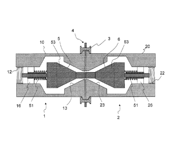
The breakaway coupling comprises a first coupling half 1
and a second coupling half 2, which are kept in the coupled
state by a series of ring segments 3. The ring segments 3
themselves are held together and pressed radially inward by a
pre-stressing element 4 at the periphery of the breakaway
coupling.
The first coupling half 1 has a tube-shaped housing 10,
which has a coupling side ha of a first system-tight end
flange or collar 11 Introduced there. A connection thread 12
for a secondary line is provided at the other end of the first
coupling half. The second coupling half 2 is largely formed
mirror-symmetrically to the first coupling half and has a
housing 20 with a second system-tight end flange or collar 21
and a second connection thread 22. Each coupling half has an
automatically closing fluid barrier 5 or 6, each of which
comprises a spring 51 or 61 and a spherical sealing element 53
or 63, which work together with a conical sealing seat 13 or
23 if an emergency disconnection is triggered. The springs 51
or 61 are supported on crosspieces 16 or 26 of the tube-shaped
housing 10 or 20.
The end flanges or collars 11 and 21 abut one another at
their coupling sides ha or 21a (Fig. 2), which also
interlock. For this purpose, the first end flange or collar 11
has a recess 14 and the second end flange or collar 21 has an
annular axial projection 24. An expansion seal 7 that has an
expansion spring 71 and a sealing lip 72 made of plastic sits
CA 2897893 2017-10-25
6
in recess 14 and works together with the axial projection 24
as the seal countersurface. The expansion spring 71, in the
shape of a closed coil spring, is composed of metal in order
to be effective even at very low temperatures, whereas
polytetrafluoroethylene or a material with similar behavior at
very low temperatures is preferred for the sealing lip 72.
On the side facing away from the coupling sides ha or
21a, the end flanges or collars 11 or 21 each have a conical
surface as oblique surface 15 or 25, the slopes of which are
directed opposite one another, when they are viewed in the
radial direction from inside to outside. The conical tips of
the two generated cones lie on the axis of the device and the
aperture angle of the cone lies in the range of 65 to 25 , a
more constricted range of 55 to 35 being preferred.
The ring segments 3 that number three or more ring
segments are distributed uniformly around the periphery of the
device and have a recess 30 on their radial inner side, which
corresponds to the shape of the radial ends of the end flanges
having the conical partial surfaces 15 and 25 that are coupled
together. Accordingly, the slopes of the edges 31, 32 of the
recess 30 correspond to the conical partial surfaces 15 and
25. The ring segments 3 have another, outer recess 34, in
which the pre-stressing element 4 engages, and the ring
segments are pressed radially inward against the conical
surfaces 15 or 25.
CA 2897893 2017-10-25
7
The pre-stressing element 4 can have different
configurations. A slotted lock washer 40 or several slotted
lock washers 40, 41 can be used as the pre-stressing element,
these lock washers being composed of a ring clasp with
openings next to the ends, in order to be able to spread apart
the slotted lock washer for assembly. The pre-stressing
element, however, can also be formed by tension coil springs,
which extend between the ring segments and hold them together.
It is also possible to produce the pre-stressing element by
one or more closed coiled springs which wrap around the ring
segments. Any design of the pre-stressing element is useful as
long as the ring segments 3 are pressed elastically against
the system sealing flanges or collars 11, 21 and develop
sufficiently strong forces that are directed radially inward.
For the functioning of the breakaway coupling, it is not
necessary to provide both edges 31, 32 as oblique surfaces in
order to work together with two conical surfaces 15, 25. Only
one of these conical surfaces is required, while a cylindrical
edge can be formed instead for the other conical surface. It
is understood that the recess 30 in the ring segments 3 is
formed correspondingly, as shown in Fig. 3. Another cuter
oblique surface 33, which is useful as a mounting aid, is
formed therein. Such a surface can also be present in the case
of the embodiment according to Fig. 2.
CA 2897893 2017-10-25
8
The mode of operation of the breakaway coupling is as
follows:
When the breakaway coupling is delivered, the ring
segments 3 embrace the end flanges or collars 11, 21, which
are coupled together, as a consequence of the forces directed
radially inward, which are introduced by the pre-stressing
element 4. Due to the radially symmetric configuration of the
breakaway coupling, the latter can be inserted into a gap in a
line run by screwing it together with the ends of the line. It
is presumed that an actuatable coupling with which the line
connection between a delivery vehicle and a tank (or vice
versa) is completed is inserted in the line run. Now, if an
excessive pull is exercised on the line by an undesired event,
the conical surfaces 15 or 25 exert a pressure on at least the
oblique countersurface 32 of the recess 30, whereby, due to
the removal of force, radial forces directed outward are
exercised on the series of ring segments 3. If these forces
exceed the retaining forces of the pre-stressing element 4
that are directed inwardly, the pre-stressing element 4
expands and the end flanges or collars 11 or 21 can be pulled
out of the recess 30. If this occurs, the coupling halves 1, 2
disengage from one another. The fluid barriers 5 or 6 are then
activated, i.e., the springs of these fluid barriers move the
sealing cone against the assigned sealing seats 13 or 23.
Undesired leakage of fluid is prevented thereby.
CA 2897893 2017-10-25
9
The breakaway coupling is re-assembled by spreading apart
the pre-stressing element 4, bringing the coupling halves 1, 2
together, and releasing the pre-stressing element 4, whereby
the ring segments 3 embrace the radial edge of the engaging
end flanges or collars 11, 21, and the breakaway coupling
again achieves its functional state.
A robust and simply constructed breakaway coupling has
thus been described and disclosed, which is provided with
system-tight end flanges 11, 21 on the first and second
coupling halves 1, 2. The end flanges 11, 21 have oblique or
conical surfaces 15, 25, and are embraced there by ring
segments 3, which in turn are pressed against the oblique or
conical surfaces 15, 25 by a pre-stressing element 4. With an
excessive pull on the coupling halves 1, 2, the latter can
separate counter to the force of the pre-stressing element 4.
CA 2897893 2017-10-25