Note: Descriptions are shown in the official language in which they were submitted.
CA 02897940 2015-07-09
WO 2014/151068 PCT/US2014/024886
TEMPERATURE SENSING CATHETER
PRIORITY
[0001] This application claims the benefit of priority to U.S.
Provisional Application
No. 61/794,849, filed March 15, 2013, which is incorporated by reference in
its entirety into
this application.
BACKGROUND
[0002] The present invention relates generally to medical catheters, and
particularly
to catheters and methods for reinforcing an inflation lumen, and also
measuring a patient's
core body temperature and wireles sly transmitting the measurements to an
external display.
[0003] Foley catheters are generally tubes having a rounded tip at a
distal end that is
inserted into the bladder of a patient, and a proximal end that remains
outside the body of the
patient. Foley catheters are typically utilized to remove urine from the
bladder of a patient.
A Foley catheter generally includes a balloon disposed at a distal end of the
catheter to
anchor the catheter in the bladder, the catheter also including at least one
drainage lumen to
drain urine from the bladder and at least one inflation lumen to inflate the
balloon (e.g., with
sterile water). The proximal end of the Foley catheter can include two ports
in
communication with the two lumens (i.e., the drainage lumen and the inflation
lumen). A
first port connected to the drainage lumen can have an interface with fittings
for drainage and
sampling, and a second port connected to the inflation lumen can have a valve
to ensure the
inflation fluid remains within the lumen and balloon once filled. The tip of a
Foley catheter
extends beyond the sides of the balloon into the bladder and includes one or
more apertures
or "eyes" to drain fluids and debris from the bladder once the tip is
positioned inside the
bladder.
[0004] Foley catheters can have issues with deflation once they are
inside a patient.
This can be due to a variety of factors that cause the balloon's inflation
lumen to collapse.
An inappropriate insertion of inflation fluid may result in an improperly
inflated inflation
lumen due to under-inflation (e.g., adding an insufficient amount of inflation
fluid to a larger
inflation balloon) and non-aspiration of the syringe (e.g., not properly
loosening or preparing
the syringe for insertion of a fluid). Also, a balloon is under abnormally
high radially inward
pressure. This radially inward pressure can result from any number of causes,
including but
-1-
CA 02897940 2015-07-09
WO 2014/151068 PCT/US2014/024886
not limited to, under-inflation of the balloon, anatomical abnormality, and
excessive traction
resulting from physician placement or patient movement The radially inward
pressure
exerted on the balloon results in a radially inward pressure exerted on the
catheter shaft,
which causes the outer surface of the catheter to push into the inflation
lumen, closing or very
nearly closing off the inflation lumen.
[0005] In addition, when a negative pressure is exerted by a syringe
trying to aspirate
fluid from the balloon, the effect can be to completely collapse the walls of
the inflation
lumen, making it difficult or impossible to deflate the balloon. Thus, even if
the inflation
lumen is properly inflated, collapse of the inflation lumen during removal and
consequent
balloon deflation results in ridges or cuff formation which can result in
urethral trauma and
make atraumatic removal of the catheter difficult or impossible. On occasion,
it proves
difficult or impossible to deflate the balloon in the normal manner. When this
happens, it
becomes necessary to take extraordinary means such as inserting an instrument
up the
catheter through the inflation lumen or through the bladder to pierce the
balloon to allow the
inflation medium to escape. These procedures may cause the patient additional
discomfort
and may lead to adverse clinical consequences.
[0006] Some Foley catheters include a temperature sensor included on the
end of the
catheter. A wire connects the sensor, via the catheter, to externally located
monitoring
devices. Use of a temperature-sensing catheter allows for convenient and
continuous
temperature monitoring, helping to maintain a normal body temperature. It also
maintains a
closed system and eliminates invasive probes to maximize patient safety. This
type of Foley
catheter typically has a thermistor or thermocouple located on or near the tip
of the device
and a wire that runs the length of the catheter to a connector that plugs into
a temperature
monitor. In some instances an additional external cable is also used, which
may or may not
be removable. However, current methods of manufacturing a temperature-sensing
catheter
can be costly and tedious, and patients in hospitals are usually inundated
with an inordinate
amount of tubing. Further, a Foley catheter with a temperature sensor cannot
be connected to
an external cable and/or the temperature monitor if the temperature sensor has
not been
shown to be safe for patients undergoing MRI examinations.
SUMMARY
[0007] Accordingly, described herein are urinary catheters including
features believed
to provide advantages over existing Foley catheters. In one embodiment, a
urinary catheter
-2-
CA 02897940 2015-07-09
WO 2014/151068 PCT/US2014/024886
includes a temperature sensor, wirelessly sending core body temperature data
to an external
display. In one embodiment, a method of manufacturing a catheter includes
integrating a
wireless temperature sensor during the manufacturing process. In one
embodiment, a method
of manufacturing a catheter includes integrating a reinforced metal support in
the inflation
lumen. In one embodiment, a urinary catheter includes an inflation lumen
reinforced with a
metal support, such as a metal braid or coil, along a portion or all of its
length.
[0008] In one embodiment, a catheter includes a proximal end and a distal
end, a
balloon disposed near the distal end proximal of a tip formed at the distal
end, a drainage
lumen extending from a drainage eye in the side wall of the tip to the
proximal end, the
drainage lumen including a superhydrophobic microstructure patterned surface,
an inflation
lumen extending from an inflation eye near the distal end in fluid
communication with the
balloon to the proximal end of the catheter, the inflation lumen including a
reinforcement
member, and a temperature sensor disposed at the distal end of the catheter
proximal the
drainage eye.
[0009] In one embodiment, a catheter includes a proximal end and a distal
end, a
balloon disposed near the distal end proximal a tip formed at the distal end,
a drainage lumen
extending from a drainage eye in the side wall of the tip to the proximal end,
an inflation
lumen extending from an inflation eye near the distal end in fluid
communication with the
balloon to the proximal end of the catheter, and a temperature sensor disposed
at the distal
end of the catheter proximal the drainage eye.
[0010] In one embodiment, a catheter includes a catheter including a
proximal end
and a distal end, a balloon disposed near the distal end proximal a tip formed
at the distal end,
a drainage lumen extending from a drainage eye in the side wall of the tip to
the proximal
end, and an inflation lumen extending from an inflation eye near the distal
end in fluid
communication with the balloon to the proximal end of the catheter, the
inflation lumen
including a reinforcement member.
[0011] In one embodiment, a method of forming a catheter includes dipping
an
inflation wire, drainage form, and temperature sensor individually in a first
coating material,
and dipping an inflation wire, drainage form, and temperature sensor
longitudinally aligned
together in a second coating material.
-3-
CA 02897940 2015-07-09
WO 2014/151068 PCT/US2014/024886
[0012] In one embodiment, a method of forming a catheter includes dipping
a
reinforced inflation wire and drainage form individually in a first coating
material, and
dipping an inflation wire and drainage lumen longitudinally aligned together
in a second
coating material.
[0013] These and other embodiments, methods, features and advantages will
become
more apparent to those skilled in the art when taken with reference to the
following more
detailed description of the invention in conjunction with the accompanying
drawings that are
first briefly described.
BRIEF DESCRIPTION OF THE DRAWINGS
[0014] The disclosed systems and methods can be better understood with
reference to
the following drawings. The components in the drawings are not necessarily to
scale.
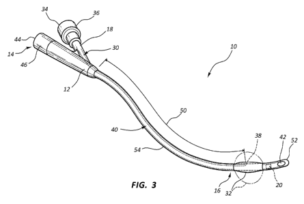
[0015] FIG. 1 shows a cross-section of a distal end of a catheter in
accordance with
the present disclosure.
[0016] FIG. 2 shows an aspect of a method of manufacturing a catheter in
accordance
with the present disclosure.
[0017] FIG. 3 shows a side view of a catheter in accordance with the
present
disclosure.
[0018] FIG. 4 shows an aspect of a method of manufacturing a catheter in
accordance
with the present disclosure.
[0019] FIG. 5 shows an exemplary superhydrophobic microstructure
patterned
surface formed in a drainage lumen in accordance with the present disclosure.
DESCRIPTION
[0020] The following description and accompanying figures, which describe
and
show certain embodiments, are made to demonstrate, in a non-limiting manner,
several
possible configurations of a catheter according to various aspects and
features of the present
disclosure.
[0021] For clarity it is to be understood that the word "proximal" as
used herein refers
to a direction relatively closer to a clinician, while the word "distal"
refers to a direction
-4-
CA 02897940 2015-07-09
WO 2014/151068 PCT/US2014/024886
relatively further from the clinician. For example, the end of a catheter
placed within the
body of a patient is considered a distal end of the catheter, while the
catheter end remaining
outside the body is a proximal end of the catheter. Also, the words
"including," "has," and
"having," as used herein, including the claims, shall have the same meaning as
the word
"comprising."
[0022] Referring to FIG. 1, a distal end 16 of catheter 10 is illustrated
in cross-section
with an inflation lumen 30, drainage lumen 40, and temperature sensor 20. The
catheter 10
comprises an elongated catheter body 12. As shown in FIG. 1, the inflation
lumen 30 may
include a reinforcement 54 as described in more detail below (e.g., with a
metal braided
material). As shown in FIG. 3, catheter 10 has a proximal end 14 and a distal
end 16. A
balloon 32 is located near the distal end 16 of the catheter adjacent the tip
52 of the catheter
10. The catheter tip 52 may have a rounded, atraumatic end. A drainage lumen
40 extends
longitudinally within the catheter body 12 from proximal end 14 to drainage
eye(s) 42 in the
side wall(s) of tip 52, and is in fluid communication with drainage eye(s) 42.
Although a
single drainage eye 42 is illustrated, it is contemplated that the tip 52 may
include multiple
drainage eyes 42. Drainage eye(s) 42 permit fluid to enter the drainage lumen
40. Drainage
eye(s) 42 may be burnished and polished for added smoothness to maximize
patient comfort.
Drainage eye(s) 42 may be relatively large holes to reduce clotting and
maximize urine flow.
[0023] The drainage lumen 40 comprises a major portion of the cross-
section of the
central region of catheter body 12. The proximal end 14 of the drainage lumen
40 is placed
in fluid communication with fluid collection or disposal equipment, such as a
urinary
drainage bag. The proximal end 14 of catheter 10 may include a drainage port
44 in fluid
communication with the drainage lumen 40. Optionally, the proximal end 14 of
catheter 10
may include a one-way drainage valve 46 that only allows fluid to drain
proximally from the
catheter 10, and prevents reflux of drained urine back into the catheter 10.
Also, proximal
end 14 of catheter 10 may include or be attached to other communication
valves, chambers,
funnels, or other devices through which the drainage lumen 40 communicates
and/or attaches
to the fluid collection or disposal equipment.
[0024] The inflation lumen 30 is formed within the wall of the catheter
body 12 and
extends from an inflation eye 38 inside of the balloon 32 to the proximal end
14 of catheter
body 12. Catheter body 12 may include a branching arm 18 in a proximal region
of the
catheter body 12 through which the inflation lumen 30 passes. In use, balloon
32 is inflated
-5-
CA 02897940 2015-07-09
WO 2014/151068 PCT/US2014/024886
once the distal end 16 of catheter 10 is positioned within a bladder of the
body of the patient,
which serves to anchor the distal end 16 in the bladder. The proximal end 14
of catheter 10
may include an inflation port 34 in fluid communication with the inflation
lumen 30 of the
catheter 10. Optionally, the proximal end 14 of catheter 10 may also include
an inflation
valve 36 that prevents fluid flow in the inflation lumen 30 unless the
proximal end 14 is
connected to a syringe or other means for inflating or deflating the balloon
32.
[0025] For urinary catheters such as Foley catheters, the catheter 10 is
introduced into
the patient and is advanced into the patient's urethra until the distal end 16
of the catheter 10,
including the balloon 32, resides within the bladder. The balloon 32 is then
inflated, typically
by coupling a syringe to the proximal end 14 of the catheter 10 such that the
syringe may
communicate with the inflation lumen 30, and actuating the syringe to
discharge fluid from
the syringe, through the inflation lumen 30, and into the balloon 32. To
remove a catheter 10,
it is first necessary to deflate the balloon 32 anchoring the distal end 16 of
the catheter 10.
This is done by withdrawing fluid through the inflation lumen 30, typically
through a syringe
coupled to the inflation lumen 30 via inflation valve 36 and inflation port
34.
[0026] The balloon 32, which in one embodiment is made of an elastomeric
material,
is positioned around the catheter shaft. The balloon 32 is preferably
engineered to retain its
shape once inflated without significantly deforming due to pressures arising
while within the
body. The balloon 32 may include ribs (e.g., thicker polymer portions or added
reinforcement) to ensure strength and symmetry of the material.
[0027] FIG. 2 describes a highly efficient method of manufacture that
allows the
formation of temperature-sensing catheters with a broad range of physical
characteristics.
The method involves manufacturing wireless temperature-sensing catheters
reinforced with a
metal element. The method of manufacturing a temperature-sensing Foley
catheter described
herein increases the quality and consistency of the catheter, as well as
allowing the outer
layers of the catheter to have broader material properties without an
overcomplicated process.
[0028] In one embodiment, efficient measurement of a patient's
temperature using the
temperature of bodily fluid is accomplished by using a temperature sensor 20
embedded in a
catheter 10 and transmitting the information wirelessly to an external
display. A temperature
sensor 20 may be embedded in a catheter 10 during the process of manufacturing
the catheter,
rather than embedding the temperature sensor 20 post-processing. A wireless
temperature
-6-
CA 02897940 2015-07-09
WO 2014/151068 PCT/US2014/024886
sensor 20 can be integrated into a catheter 10 to sense temperature inside the
body without
the need to connect wires. This leads to a completely embedded temperature
sensor 20 that
has no risk of patient contact.
[0029] The catheter 10 may be manufactured by dipping, for example by the
methods
described in U.S. Patent No. 7,628,784, which is incorporated by reference in
its entirety into
this application. In one embodiment, in step 401, an elongated rod or "form"
is dipped into a
first liquid coating material to form a first layer of coating material on the
form. The form
has the shape and dimensions of the drainage lumen 40 of the catheter 10. This
first coating
layer forms the first layer of the catheter 10. In step 402, the temperature
sensor 20 is also
separately dipped into a first liquid coating material. In step 403, once the
first layer has
dried, an elongated wire is attached longitudinally to the outside of the
first layer. In step
404, the form with first layer, temperature sensor 20, and an elongated wire
(used to form the
inflation lumen 30) is then dipped into a second coating material to form a
second layer.
[0030] Alternatively, the temperature sensor 20 may be dipped only once,
i.e., dipped
only into the second coating without being first coated previously. Multiple
dips into the
second coating material may be necessary to form a second layer of appropriate
thickness.
The inflation eye 38 is then formed near the distal end 16 of the second layer
to place the
inflation lumen 30, formed by the elongated wire, in communication with the
second layer.
The second layer is then dried. Optionally, a third layer is applied with a
subsequent dip and
is dried.
[0031] The balloon 32 can be formed in a number of ways. In some
preferred
embodiments, the balloon 32 is formed by attaching a pre-formed balloon
component to the
second layer. In other embodiments, a masking material is applied to the
exterior of the
second layer in the balloon formation area such that upon dipping to form a
third layer, a
bond does not form between the second layer and the third layer in the balloon
formation area
near the inflation eye 38 of the inflation lumen 30. In such embodiments, the
un-adhered
portion of the third layer may form the balloon 32. Optionally, the form with
first and second
layers and the balloon formation layer is then dipped into another coating
solution to form a
third layer. Alternatively, no final layer may be used, e.g., the pre-formed
balloon component
or third layer used to form the balloon 32 forms the outermost wall of the
balloon 32.
-7-
CA 02897940 2015-07-09
WO 2014/151068 PCT/US2014/024886
[0032] Once the third layer has dried, the catheter 10 is removed from
the form. The
space formerly occupied by the form and the elongated wire becomes the
drainage and
inflation lumens 40 and 30 (respectively). The balloon 32 can be inflated by
infusing an
inflation medium into an inflation port 44, through the inflation eye 38 of
the inflation lumen
30 and into the balloon 32.
[0033] As discussed above, the catheter shaft beneath the balloon 32 may
comprise
two layers, a first layer and a second layer. Optionally, the first and second
layers are formed
from the same or similar material, typically latex or silicone, such that the
resulting
composite structure is essentially homogenous. It will be appreciated that the
catheter shaft
in some embodiments may comprise three layers, an inner layer, an intermediate
layer, and
an outer layer bonded to the outer surface of the intermediate layer.
[0034] The inflation lumen 30 runs parallel to the surface of the second
layer until a
point where the inflation lumen 30 is in fluid communication with the interior
of the balloon
32 (e.g., at a point beneath the balloon 32). The portion that communicates
with the interior
of the balloon 32 is referred to herein as the inflation eye 38. At the
proximate end of the
catheter 10, the inflation lumen 30 branches off along branching arm 18 and
terminates at the
proximal end 14 of the catheter 10. A syringe engages the inflation valve 36
to infuse an
inflation medium such as sterile water through the inflation lumen 30 to
inflate the balloon
32.
[0035] Drainage eye(s) 42 are then formed (e.g., cut) in the distal end
16 of catheter
distal of the balloon 32, such that the drainage lumen 40 is in fluid
communication with
the drainage eye(s) 42. It should be appreciated that although a single
drainage eye 42 is
illustrated, it is contemplated that the tip 52 may include multiple drainage
eyes 42.
[0036] In one embodiment, a wireless temperature sensor 20 is added mid-
process to
a catheter 10 as a single step instead of multiple post-processing steps to
place a wireless
temperature sensor 20 into a catheter 10 after manufacturing. As such, a
purpose-built
wireless temperature sensor 20 (e.g., a thin metal strip, film strip, circuit,
wire, etc.), is
integrated into the manufacturing process discussed above. It is carried
through the rest of
the Foley manufacturing process such that it is permanently integrated into
the temperature-
sensing Foley catheter 10.
-8-
CA 02897940 2015-07-09
WO 2014/151068 PCT/US2014/024886
[0037] The catheter 10 may be formed using a dip-coating process by
dipping the
wireless temperature sensor 20 and elongated form separately into a first
coating material,
and dipping the entire catheter 10, including the temperature sensor 20,
elongated form, and
an elongated wire in a second coating material, which coats both the entire
inner and outer
surfaces of the catheter 10 and causes the coating materials to be in direct
contact with the
surfaces. The catheter 10 may be coated with latex (most widely used among
clinicians), red
latex (stiffer and radiopaque), Silastic material (firm but flexible, latex-
based construction
with smooth, nonstick silicone elastomer coating to reduce calcification build-
up), or silicon,
among other materials listed below. Catheter 10 may also be coated with an
outer hydrogel
coating to reduce friction, a major cause of irritation, and generally to
improve patient
comfort and safety. This is especially effective with latex and silicone
catheters. A multiple-
dip manufacturing process may be used to ensure a smooth surface with no
excess material to
cause irritation. Preferably, tip 52 is precisely molded to eliminate excess
material that can
cause irritation.
[0038] The following materials may be used in the manufacture of catheter
10:
natural rubber latexes (available, for example, from Guthrie, Inc., Tucson,
Ariz.; Firestone,
Inc., Akron, Ohio; and Centrotrade USA, Virginia Beach, Va.), silicones
(available, for
example, from GE Silicones, Waterford, N.Y., Wacker Silicones, Adrian, Mich.;
and Dow
Coming, Inc., Midland, Mich.), polyvinyl chlorides (available, for example,
from Kaneka
Corp., Inc., New York, N.Y.), polyurethanes (available, for example, from
Bayer, Inc.,
Toronto, Ontario, Rohm & Haas Company, Philadelphia, Pa.; and Ortec, Inc.,
Greenville,
S.C.), plastisols (available, for example, from G S Industries, Bassett, Va.),
polyvinyl acetate,
(available, for example from Acetex Corp., Vancouver, British Columbia) and
methacrylate
copolymers (available, for example, from Heveatex, Inc., Fall River, Mass.).
However, other
materials not listed may also be used. Natural rubber latexes, polyurethanes,
and silicones
are preferred materials. Also, any combination of the foregoing materials may
be used in
making catheters. For example, an outer layer that includes latex and a
methacrylate may be
used with second and third layers that include latex but not methacrylate.
Additionally, a
polyurethane rubberize layer may used with latex second and third layers.
Also, a polyvinyl
acetate and latex rubberize layer may be used with latex second and third
layers.
[0039] The above list of materials that can be used above in making
catheters is not
intended to be exhaustive and any other materials that can be used are within
the scope of the
-9-
CA 02897940 2015-07-09
WO 2014/151068 PCT/US2014/024886
invention. In addition, catheters 10 of the present invention are not limited
to those having
three layers of material. Any combination of layers can be used. For example,
one or more
additional coatings may be applied to the surface of the catheters 10 to
provide lubricity, to
reduce risk of infection, or for any other purpose.
[0040] Multiple types of wires are compatible with a catheter dipping
process. A
wire was tested using a resistor the same size as available temperature
sensors 20 that meet
current processing and use environments and specifications. In an exemplary
embodiment, a
fine copper wire that is coated (e.g., so as not to disrupt the latex) may be
used. A coated
wire may be effectively integrated into a latex dipping processes (i.e., can
be coated in the
latex dipping process) and is not detrimental to the solutions. Conformational
coatings are
also able to properly integrate into manufacturing by dipping. In an exemplary
embodiment,
an acrylic type of conformational coating may be used.
[0041] To ensure the ease of application of the temperature sensor 20 and
flexibility
of the catheter 10, a thin metal strip or film strip is preferred as the
temperature sensor 20.
The circuit is separated from the catheter 10 at sufficient distance from the
catheter's 10
proximal end 14 to ensure it does not interfere with cutting equipment.
[0042] It is contemplated that the catheter 10 includes a temperature
sensor 20
capable of wirelessly transmitting a signal derived from the temperature
sensor 20 to a
wireless receiver in an external display. A catheter 10 is engaged within the
patient (e.g., the
balloon is expanded in the bladder), and the catheter 10 includes a
temperature sensor 20 that
generates a signal representative of the patient's body temperature.
Additional sensors may
be used in addition to, or in lieu of, the temperature sensor 20 to detect and
measure
additional vital signs, for example sensors described in U.S. Publication No.
2013/0066166,
which is incorporated by reference in its entirety into this application.
[0043] The temperature sensor 20 includes a wireless transmitter capable
of
wireles sly transmitting a signal representative of patient's temperature to
the external display,
which includes a receiver. Wireless temperature detection could occur in a
variety of ways.
In one embodiment, short range radiofrequency (RF) principles may be used. One
short range
RF protocols that can be used is Bluetooth technology. Wireless 802.11
communication
principles may also be used.
-10-
CA 02897940 2015-07-09
WO 2014/151068 PCT/US2014/024886
[0044] Various methods can be used to power the circuit of the
temperature sensor
20. In one embodiment, the temperature sensor 20 may be energized by a power
source such
as a small battery. One embodiment provides for an unpowered wireless
temperature sensor
20 at the tip 52 of the catheter 10 and a secondary device attached to the
patient's catheter 10
or abdomen in order to power the wireless temperature sensor 20 and detect
temperature.
[0045] In one embodiment, the catheter 10 contains an unconnected,
unpowered, and
completely embedded circuit with the temperature sensor 20. The circuit
extends from the
distal end 16 to the proximal end 14 within the catheter 10. To power the
wireless
temperature sensor 20, a separate device is placed over the distal end 16 of
the catheter 10
that can induce current into the circuit and measure the resistance/voltage
drop across the
circuit. This is similar to an radio-frequency identification (RFID) loop that
is unpowered,
but can be scanned and activated.
[0046] One embodiment provides for a powered circuit with a wireless
temperature
sensor 20 at the tip 52 of the catheter 10 and a circuit near the proximal end
14 of the catheter
with an antenna, which is battery powered and would last at least beyond the
allowable
use of the catheter 10. Other methods of powering the circuit, such as body
heat, could also
be used.
[0047] The wireless temperature sensor 20 could also communicate with
other
electronic medical record systems or have warnings about a patient's
temperature to give
clinicians feedback about a patient's health. Also, the catheter 10 could
include on-board
storage and data-logging of a patient's temperature for reading and
identification at a later
point in time.
[0048] The wireless temperature sensor 20 may interact with an external
display, such
as C. R. Bard Inc.' s CritiCore Patient Monitoring System. This allows a
clinician to
accurately measure core body temperature and urine output without the expense
or patient
inconvenience of invasive temperature probes. Maintaining a normal core body
temperature
may result in fewer adverse outcomes ¨ including an increased risk of surgical
site infection,
morbid cardiac events, ventricular tachycardia, wound infection and blood loss
¨ with a
resulting decrease in costs. Such a system can be used with a communication
module to
connect to a hospital's clinical information system for paperless management
of vital signs.
-11-
CA 02897940 2015-07-09
WO 2014/151068 PCT/US2014/024886
It should be appreciated that while sensing temperature is described, other
vital signs, such as
heart beat, breathing rate, and blood pressure, may also be measured.
[0049] FIG 3 is side cross-sectional view of a catheter 10 with a
deployed inflation
lumen 30, and a braided section 50 of a reinforcement 54 extending from a
balloon 32 to a
proximal end 14 of the catheter 10. It should be appreciated that the
temperature sensor 20
alternately may be embedded at different points along the distal end 16 of the
catheter 10. In
one embodiment, the temperature sensor 20 is located adjacent a drainage eye
42. In one
embodiment, the temperature sensor 20 is located proximal the balloon 32
further down the
catheter shaft. FIG. 3 illustrates an embodiment of the temperature sensor 20
located
proximal the balloon 32, such that the inflation lumen 30, drainage lumen 40,
and
temperature sensor 20 are shown in cross-section. Closer to the drainage eye
42, a cross-
section of the catheter 10 would not include the inflation lumen 30.
Alternatively, various
other locations for the temperature sensor 20 are possible.
[0050] The failure of a balloon 32 of a Foley catheter 10 to deflate
represents a device
failure that requires intervention. This is often related to inflation lumen
30 collapse. It can
also be caused by pulling a vacuum on the inflation lumen 30 when trying to
drain it too
quickly. The present catheter 10 would prevent this situation entirely.
[0051] Since lumen collapse is generally the main cause of a non-
deflating catheter,
the inflation lumen 30 can be reinforced with a metal or plastic braid or
coil. Preferably, any
metal used is MRI compatible, such as MP35N, nickel-cobalt base alloy, and
allows shaping
the reinforcement 54, and catheter 10, with a thin profile. Kevlar, poly-
paraphenylene
terephthalamide, may also be used. The reinforcement 54 may be provided by a
thin metal
braid, although other materials are possible, such as shape memory alloys,
etc. Shape
memory alloys include copper-aluminum-nickel, copper-zinc-aluminum, and iron-
manganese-silicon alloys. In one embodiment, the reinforcement 54 of the shaft
is provided
by a material, such as Nitinol, that imparts radial strength to the catheter
body 12 to permit
insertion without inflation lumen 30 collapse, but is soft and flexible after
insertion (e.g., due
to changing of properties due to temperature) to enhance patient comfort.
[0052] Catheter 10 with reinforcement 54 is believed to provide
advantages with
respect to, for example, maximizing drainage, ease of manufacture, ease of
insertion,
-12-
CA 02897940 2015-07-09
WO 2014/151068 PCT/US2014/024886
prevention of lumen collapse due to axial stiffness of catheter shaft,
enhanced patient
comfort, faster inflation and deflation times, etc.
[0053] With the catheter 10 in place, the risk of inflation lumen 30
collapse is
significantly reduced. A reinforcement 54, such as a braided metal support, in
the inflation
lumen 30 for the prevention of inflation lumen collapse also resists collapse
under vacuum
conditions. Such a support would allow for the other layers of the catheter 10
to have broader
material properties and still maintain consistent functionality. Previously,
preventing lumen
collapse has been accomplished with nylon-reinforced catheters. While a nylon
braid or tube
may be used, a thin metal braid is a preferred embodiment, as a metal braid is
small enough
to support the inflation lumen 30 without causing significant geometry changes
to the
catheter 10. A drainage lumen 40 with a metal braid support also easily
integrates into the
same process as catheter 10 dipping process outlined above. A metal-reinforced
drainage
lumen 40 would result in superior flow properties and resistance to kinking.
[0054] As illustrated in FIG. 4, the steps for manufacturing a catheter
10 with
reinforcement 54 are similar to the manufacturing steps described above.
However, in
addition, in step 501, a cylindrical braided or coiled wire would be placed
over an elongated
wire used to form an inflation lumen 30 prior to dipping. The elongated wire
would then be
dipped in a first coating material in step 502. In step 503, the elongated
wire would be
attached longitudinally to the outside of a first layer separately formed on
the elongated form
used to form the drainage lumen 40. In step 504, the elongated wire and
elongated form
would be dipped in a second coating material. During the dipping process, the
coating
material integrates into the braid or coil and prevents the braid or coil from
coming out of the
catheter 10 upon removal of the elongated wire. It should be appreciated that
the
reinforcement section 50 may extend up to the inflation eye 38 or past it as
long as a
sufficient amount of water can pass through the braid or coil to allow
inflation and deflation
of the balloon 32.
[0055] With regard to FIG. 5, to improve urine drainage through the
catheter 10 and
reduce urine surface tension on the lumen walls of catheter 10, the drainage
lumen 40 of
catheter 10 is preferably coated with a hydrophobic coating or treatment,
and/or formed to
include a patterned microstructure surface design, such as superhydrophobic
patterned
surface 48. This provides a better emptying mechanism and prevents fluid from
being held
for too long within the catheter 10. This also provides immediate fluid flow
without
-13-
CA 02897940 2015-07-09
WO 2014/151068 PCT/US2014/024886
columnating within the drainage lumen 40 and reduces unwanted fluid within the
bladder and
drainage lumen 40. Surface tension of the catheter 10 material (e.g.,
silicone) can cause the
fluid passing through the catheter 10 to columnate instead of flowing
continuously.
Columnation can lead to the fluid (e.g., urine) backing up and not flowing
properly though
catheter 10. Columniation can leave residual fluid backed-up in the bladder,
and leave
residual fluid in the drainage lumen 40, which can lead to sanitation and
health issues as well
as errors in measurements of urine production and flow.
[0056] To prevent columnation, a hydrophobic coating or lubricious
treatment may be
added to the surface of the drainage lumen 40. Optionally, a patterned design
can be used on
the hydrophobic inner surface of the drainage lumen 40 to create
superhydrophobic inner
lumen surfaces and prevent columnation. The contact angles of a water droplet
on a
superhydrophobic surface may exceed 150 and the roll-off angle may be less
than 10
making the superhydrophobic surface extremely difficult to wet.
Superhydrophobicity can be
obtained by artificially adding small-scale roughness to hydrophobic surfaces
to keep
droplets in a Cassie Baxter state, i.e., a state in which air remains trapped
inside the
microscopic crevasses below the droplet. The roughness of a surface decreases
the
wettability of hydrophobic surfaces resulting in an increased water-
repellency. Wettability
characteristics are those surface parameters which are directly linked to the
wetting nature of
materials; for instance, the contact angle is the angle the liquid droplet
makes with the solid
surface, and the surface free energy is the energy associated with the solid
surface giving rise
to the contact angle. Energetically the best configuration for the drop is on
top of the
corrugation like "a fakir on a bed of nails."
[0057] Also, a droplet on an inclined superhydrophobic surface generally
does not
slide off; it rolls off. A benefit of this is that when the droplet rolls over
a contamination,
(e.g., dirt, dust, pollution, or viral/bacterial material, etc.) the
contamination is removed from
the surface if the force of absorption of the particle is higher than the
static friction force
between the particle and the surface. Usually the force needed to remove a
particle/contamination is very low due to the minimized contact area between
the
particle/contamination and the surface. Accordingly, superhydrophobic surfaces
have very
good self-cleaning properties, and the growth of bacterial colonies is
inhibited on the water
repellant surfaces.
-14-
CA 02897940 2015-07-09
WO 2014/151068 PCT/US2014/024886
[0058] A superhydrophobic patterned surface 48, e.g., as shown in FIG. 5,
may be
formed on the surface of drainage lumen 40 such that liquid droplets will
always be in the
Cassie Baxter state, which improves the drainage and fluid flow inside the
drainage lumen 40
and helps prevent columnation. Preferably, the superhydrophobic patterned
surface 48 has a
liquid/urine contact angle greater than 1500 for extraordinary liquid/urine
repelling properties
and to eliminate the fluid columnating inside the catheter. Superhydrophobic
patterned
surface 48 may include tapered, cylindrical or squared microstructures (e.g.,
pillars) of a
certain height and diameter and with a fixed pitch.
[0059] The superhydrophobic patterned surface 48 can be added to the
surface by
etching into the surface of a dipping form used to create the inner surface of
the drainage
lumen 40, or by adding an external flexible structure that is adhere to the
dipping form before
the catheter dipping process starts. Superhydrophobic surfaces could be
fabricated from
micro-arrays of RTV or any other type of polymer with pillars or posts pitches
ranging from
450 to 700 microns. Preferably, the height of uniform pillars or post of a
superhydrophobic
surface is between 250[1.m-500[1.m, but the height can range as high as 800
[t.m. Optionally,
UV cured silicone posts at 400 [tm pitch fabricated by dispensing layers of
adhesive on top of
a flexible substrate can be used. In some embodiments, the posts or pillars
have a diameter of
between 50-175 [t.m. FIG. 5 shows an exemplary superhydrophobic patterned
surface 48
formed on the entire inner surface of a drainage lumen 40. Although FIG. 5
shows the
exemplary superhydrophobic patterned surface 48 as being on the entire inner
surface of the
drainage lumen 40, it is contemplated that the superhydrophobic patterned
surface 48 may be
on a portion of the inner surface of the drainage lumen 40.
[0060] One method of forming the microstructures (e.g., pillars or posts)
of
superhydrophobic patterned surface 48 is using a laser to form the inverse of
the
pattern/microstructures on the surface of a dipping form or mold that is then
used to create
the desired surface. Lasers can be used on the surfaces of many different
materials ranging
from ceramics, to metals, to polymers. Lasers have the ability to change both
the surface
dimensions (roughness and surface pattern) and the surface chemistry
simultaneously which
can then lead to a change in the wettability characteristics. Superhydrophobic
patterned
surfaces can also be prepared on a wide variety of surface shapes using a
commercially
available 3D printer for fabrication of large, complex polymer objects on a
flat surface that
later can be incorporated into the form, for the dipping process. This can be
achieved where
-15-
CA 02897940 2015-07-09
WO 2014/151068 PCT/US2014/024886
the micro-textured surface is monolithic with the body or flexible structure.
The
superhydrophobic behavior, such as the water column height supported, can be
described by
the same equations as those used to describe superhydrophobic behavior on
surfaces with
nano-scale textural features, thus eliminating the need for hydrophobic
coatings.
[0061] The above embodiments have generally been described as being
applied to a
Foley catheter; however, the principles described may be applied to other
types of catheters,
e.g., angioplasty balloon catheters. Further, the features described in one
embodiment may
generally be combined with features described in other embodiments.
[0062] While the invention has been described in terms of particular
variations and
illustrative figures, those of ordinary skill in the art will recognize that
the invention is not
limited to the variations or figures described. In addition, where methods and
steps described
above indicate certain events occurring in certain order, those of ordinary
skill in the art will
recognize that the ordering of certain steps may be modified and that such
modifications are
in accordance with the variations of the invention. Additionally, certain of
the steps may be
performed concurrently in a parallel process when possible, as well as
performed sequentially
as described above. Therefore, to the extent there are variations of the
invention, which are
within the spirit of the disclosure or equivalent to the inventions found in
the claims, it is the
intent that this patent will cover those variations as well.
-16-