Note: Descriptions are shown in the official language in which they were submitted.
CA 02898084 2015-07-13
WO 2014/125405
PCT/1B2014/058861
TITLE: Apparatus and Methods for Harnessing Osmotic Potential and
Methods of Making and Using Same
FIELD OF THE INVENTION
[00011 The present application provides a unique hollow fiber (HF) or tubular
semipermeable membrane element (hereafter "HF membrane element"), apparati
comprising the HF membrane element, and methods for using the HF membrane
element and apparatus.
Background
[0002] Osmosis has been used to treat industrial wastewaters, to concentrate
landfill
leachate, and to treat liquid foods in the food industry with low salinity
content.
Recent developments in material science also have allowed the use of osmosis
in
controlled drug release and in dialysis.
[0003] Compared to other industrial separation processes, osmosis has the
advantage
of operating at low to no hydraulic pressure; rejecting a wide range of
contaminants;
possibly having a lower membrane fouling propensity; and, using relatively
simple,
basic equipment.
[0004] Attempts have been made to use osmosis to generate power, but with
limited
success. One problem lies in the design of conventional semipermeable membrane
elements, known commercially as modules or vessels. Currently
available
semipermeable membrane elements comprise tubular cylinders with relatively
small
bores, typically around 200 mm (8 inches) or less. A typical length of the
currently
available semipermeable membrane elements is only from about 1000-1500 mm.
[0005] Larger scale osmosis plants than those currently in existence, such as
large
scale power generation plants, would handle massive quantities of brine and
produce
large in-situ changes in flow rate within plant cells. Conventional osmosis
hollow
fiber or spiral wound membrane modules might be suitable for very small power
generation applications and research and development work, but would not be
efficient for use in large scale osmotic plants. First of all, a large scale
osmotic
process would comprise multiple cells and would require the use of hundreds of
thousands, if not millions, of these relatively small conventional
semipermeable
membranes. Secondly, if such a massive number of conventional semipermeable
membrane elements were used in a large scale osmotic process, the result would
be an
1
CA 02898084 2015-07-13
WO 2014/125405
PCT/1B2014/058861
excessive pressure drop that would seriously impact plant efficiency and
complicate
plant operation and cost of maintenance.
[0006] More efficient semipermeable membrane elements are needed for use in
designing large scale osmosis plants.
Summary
[0007] In one embodiment, the application provides an apparatus comprising: a
membrane element comprising a hollow fiber (HF) stack comprising a plurality
of
loosely packed hollow fibers (HFs) comprising first ends extending through one
contact structure and opposed ends extending through an opposed contact
structure,
each HF comprising an elongated lumen extending between the one contact
structure
and the opposed contact structure and comprising a hydrophilic semipermeable
membrane adapted to achieve salt rejection of 98.5% or more and exhibiting a
surface
tension of 35 dynes/cm or more; the membrane element being adapted to be
encased
in a frame and submersed in a first fluid and for induced osmosis between
lumens of
the plurality of loosely packed HFs and the first fluid, the membrane element
having
sufficient mechanical integrity when encased in the frame and submersed in the
first
fluid to sustain turbulence flow across and along surfaces of the plurality of
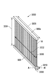
loosely
packed HFs at a Reynolds' Number of about 3,000 or more and to maintain said
mechanical integrity at feed pumping pressures of 30 bars or higher.
[0008] In one embodiment, the application provides a method comprising:
precharging HFs of one or more closed loops of the claimed apparatus with a
process fluid having an initial solute content;
charging a feed through the one or more closed loops, the feed having a solute
content greater than the initial solute content;
spontaneously permeating water from the feed to the process fluid in the HF
lumens without the need for external force, producing a concentrated
feed and a diluted process fluid.
[0009] In one embodiment, the application provides a method comprising:
precharging a plurality of the claimed closed loops of the apparatus in series
with an initial brine having an initial salt concentration sufficiently
high to create a hydraulic head effective to reach an intended elevation;
2
CA 02898084 2015-07-13
WO 2014/125405
PCT/1B2014/058861
spontaneously permeating water across a semipermeable membrane into a
riser of an initial closed loop, the water permeating from a lower salt
content brine to a higher salt content brine without the need for
external force;
developing a column in the plurality of closed loops in series, the column
exhibiting a hydraulic head equivalent to the difference in osmotic
pressure across the semipermeable membrane of the respective closed
loop;
employing the hydraulic head to sustain and convey the column from an initial
closed loop at an initial elevation to a final closed loop at a
substantially higher intended elevation; and,
collecting a quantity of desalinated brine at the substantially higher
altitude in
a quantity comprising a volume of water that spontaneously permeates
from the initial brine to the initial closed loop at an initial elevation.
[00010] In one embodiment, the application provides a method comprising:
providing a power train comprising the claimed apparatus comprising a
plurality of cells, the plurality of cells comprising an initial end cell,
one or more intermediate cells, and an opposed end cell, each cell in
the plurality of cells forming a hydraulic loop configured of specified
volumetric and flow capacity for a specified permeate flux, each cell in
the plurality of cells also having a pumping system and a hydro-power
generation turbine system, wherein adjacent cells in the plurality of
cells share a semipermeable membrane;
charging each cell in the plurality of cells with a given brine having a
specified
ionizable inorganic salt concentration and type, without permitting
mixing of the given brines among the adjacent cells in the plurality of
cells, creating a gradient of salt concentration and resulting osmotic
potential that progressively increases stepwise from the initial end cell,
across the one or more intermediate cells, to the opposed end cell;
feeding to the power train an initial brine comprising low to no salt
concentration water at the initial end cell, producing a concentration
field across the plurality of cells comprising a progressively increasing
3
CA 02898084 2015-07-13
WO 2014/125405
PCT/1B2014/058861
concentration and osmotic pressure ratio bounded by water of low to
no salt concentration at the initial end cell and by a concentrated brine
at the opposed end cell, thereby producing a power train cycle
comprising a controlled concentration-pressure loop wherein the
concentration field: (a) osmotically induces a continuous and constant
flow rate of substantially salt-free permeate flux throughout the power
train; (b) maintains a salt concentration difference across the
semipermeable membrane shared by the adjacent cells in the plurality
of cells; (c) defmes a salt concentration ratio within each cell that
ensures a net positive power generation; and, (d) discharges the
concentrated brine at the opposing end cell; and
operating the power train under conditions effective to generate net positive
power.
[00011] In one embodiment, the application provides a method of making a
membrane element comprising:
a. providing a plurality of detachable spacer structures having given
dimensions;
b. placing one or more first spacer structures on an HF assembly
platform;
c. extending a first row of first HFs with first spaces therebetween over
the one or more first spacer structures aligned with the longitudinal
axis of the HF assembly platform, forming a first longitudinal row of
first HFs, the first spaces having a width effective according to flow
dynamic calculations to maintain turbulence flow across and along
surfaces of the hollow fiber membranes at a Reynolds Number of
3,000 or more;
d. placing one or more second spacer structures having the given
dimensions over the first row of I-IFs aligned with the one or more first
spacer structures;
e. extending an adjacent row of HFs with second spaces therebetween
across the one or more second spacer structures aligned with the
longitudinal axis of the HF assembly platform;
4
CA 02898084 2015-07-13
WO 2014/125405 PCT/1B2014/058861
f. repeating (d)-(e) with additional rows of HFs and spacer structures,
forming a stack of alternating rows of HFs and intervening spacer
structures, the stack having a desired total stack depth, wherein
vertically aligned adjacent surfaces of the stacked spacer structures
define potting chambers at opposed ends of the HFs, the potting
chambers defining an inner surface having predetermined dimensions.
Brief Description of the Drawings
[00012] The application will be better understood with reference to the
drawings. Where possible, like elements contain like numerals:
[00013] Figure 1 is a cross section through a plurality of vertical hollow
fibers
and one support member of a panel.
[00014] Figure 1A is a perspective view of an individual hollow fiber.
[00015] Figure 2 is perspective view of a pair of panels comprising
perpendicularly oriented hollow fibers.
[00016] Figure 3 is a perspective view of an array for use in a power
train, the
array comprising a plurality of alternating perpendicularly oriented pairs of
panels.
[00017] Figure 3A is an exploded view of panels from the array of Fig.
3.
[00018] Figure 3A-1 is a frontal view of a vertical fiber panel.
[00019] Figure 3A-2 is a side view illustrating fluid flow across the
array of
Fig. 3A-1.
[00020] Figure 3B is an exploded view of panels from a desalination
array.
[00021] Figure 3C is a perspective view of a desalination array.
[00022] Figure 3D is a cross-section of a fiber reinforced plastic
(FRP) panel
for a hollow fiber panel.
[00023] Figure 3E is a cross-section of a steel frame or FRP for a hollow
fiber
panel
[00024] Figure 3F is a cutaway/transparent frame perspective view of a
panel
10 (Fig. 2) comprising the header 16 and an adjacent header 26 (Fig. 2).
[00025] Figure 3G is a perspective view of a vertical baffle and a
horizontal
baffle.
5
CA 02898084 2016-12-22
[00026] Figure 4 is a cross section through a plurality of conventionally
packed hollow
fibers.
[00027] Figure 5 is a cross section through of a plurality of loosely
packed hollow
fibers.
[00028] Figure 6 is a frontal view of a rectangular vessel at a vertical
panel, the
rectangular vessel being adapted for use with high pressures inside of the
hollow fibers and
low pressures outside of the hollow fibers.
[00029] Figure 7 is a cross section through a cylindrical vessel at a
vertical panel, the
cylindrical vessel being adapted for use with low pressures inside of the
hollow fibers and
high pressures outside of the hollow fibers.
[00030] Figure 8 is a top view illustrating an array 800 comprising a
plurality of
segments 802a-e of progressively differing diameters comprising sections 802
and a plurality
of arrays 804, 806, 808, 810, 812 having correspondingly differing cross-
sections.
[00031] Figure 9 is a top view illustrating an alternate embodiment 98 of
the array of
Figure 8 comprising an anay casing 92 comprising a continuously tapered
diameter
comprising a plurality of arrays 92a-e comprising continuously tapering cross-
sections 98a-e.
[00032] Figure 9A is a schematic top view of a space saving arrangement
of arrays 98,
98a, 98b for a power train containing multiple cells CELL 1, CELL 2, CELL Ir.
[00033] Figure 9B is another schematic top view of a space saving
arrangement 500 of
arrays 504, 504a-g for a power train containing a primping station 502 and
multiple cells
CELL 1, CELL 2, CELL n-1, CELL n.
[00034] Figure 10 is a top view of a power train comprising three cells
CELL 1, CELL
2, CELL n of segmented arrays 350m 350a, 350b limited by maximum allowable
operating
pressure of the plurality of HFs 352, 354.
[00035] Figure 11 is a top view of a last cell in a power train comprising
multiple cells
comprising a pressure vessel comprising a plurality of segments of
progressively differing
diameters.
[000361 Figure 11A is a top view of a power train comprising a high
pressure section
and a low pressure section.
[00037] Figure 12 is a top view of a final two cells in a power train
comprising
multiple cells having the configuration of Fig. 11.
[00038] Figure 13 is a top view of a final cell of an exchanger
comprising multiple
pressure vessels having the structure generally described in Figure 11.
6
CA 02898084 2015-07-13
WO 2014/125405
PCT/1B2014/058861
[00039] Figure 14 is a top view of cell similar to Figure 11 comprising
flexible
feed conduits, the cell fitted with electromagnetic vibrators for
concentration
polarization control.
[00040] Figure 14A is a frontal view of a vertical panel in the cell of
Fig. 14,
illustrating a pair of the electromagnetic vibrators, a pair of spring
mountings, and a
pair of array casing support members.
[00041] Figure 15 is a top view of an integrated plant comprising the
last cell of
a large scale induced symbiotic osmosis (ISO) power train and a seawater
desalination
cell comprising an array similar to that of Figure 3C.
[00042] Figure 16 is a side view of a three cell water extraction-water
recovery
system 300 for concentrating diluted fluids by extracting its water content,
particularly water contaminated with radioactive material.
[00043] Figure 17 is a schematic illustrating the pressures and tie
lines of an
ISO-Reverse Osmosis unit suitable for water extraction-fluid concentration.
[00044] Figure 18 is a cross section through a contact structure adapted to
retain opposed ends of the HFs.
[00045] Figure 18A is a cross section of a HF indicating an inner and
outer
diameter.
[00046] Figure 19 is a cross section through the rows of HFs 34 that
extend
between contact structures in an intermediate phase during assembly with
spacers
therebetween.
[00047] Figure 20 is a perspective view of an assembly for
manufacturing the
membrane element.
[00048] Figure 21 is a cross section through the assembly of Fig. 20
with only
.. two HFs, depicting the HFs as weighted.
[00049] Figure 22 is a top view of an assembly of Fig. 21 during
manufacture
of the HF panels.
[00050] Figure 23 is a side view of the assembly of Fig. 22.
[00051] Figure 24 is a cross section through an assembly comprising
spacers
adapted to form a potting structure, minus HF roll or loom heddle.
[00052] Figure 25 is a top view of one embodiment of a spacer.
7
CA 02898084 2015-07-13
WO 2014/125405
PCT/1B2014/058861
[00053] Figure 26 is a perspective view of the HF membrane element
comprising opposed contact structures with layers of HFs extending
therebetween.
[00054] Figure 27 is a top view of a HF membrane element with HFs
extending
between opposed contact structures showing a set of spacers aligned with
finished
baffles.
[00055] Figure 27A is a cross section through Fig. 27 at line X-X
before
injecting potting material.
[00056] Figure 27B is a cross section through Fig. 27 at line X-X after
injecting
and curing potting material.
[00057] Fig. 28A is a side view of an assembly for manufacturing the
membrane element comprising two rolls one for the layer of even FIB and the
second
for the layer of odd HFs.
[00058] Fig. 28B is a top view of an assembly for manufacturing the
membrane
element comprising a wide HF wrap beam (roll) supporting two simultaneous I-EF
panels assembly lines.
[00059] Fig. 28C is a perspective view of an assembly for manufacturing
the
membrane element comprising multiple spools of HFs.
[00060] Fig. 28D is a schematic top view of an assembly comprising a
first
spool row comprising an even number of HFs alternating with a second spool row
comprising an odd number of HFs.
[00061] Fig. 28E is perspective view of an assembly for manufacturing
reels of
HFs from a plurality of spools.
[00062] Fig. 28F is a schematic top view of an assembly comprising a
plurality
of adjacent reels of HFs which may be spaced, as required, to produce the
alternating
rows of odd an even HFs.
[00063] Fig. 28G is a schematic view of a wrap beam assembly with the
plurality of HFs extended from HF reels or spools being brought from different
sources.
[00064] Fig. 29A and Fig. 29B, together, are an exploded view of a
membrane
element separated from a frame of one embodiment of a hollow fiber panel.
8
CA 02898084 2015-07-13
WO 2014/125405
PCT/1B2014/058861
Definitions
[00065] "Osmosis":
The spontaneous movement of water, through a
semipermeable membrane that is permeable to water but impermeable to solute,
the
water moving from a solution in which solute is less concentrated to a
solution in
which solute is more concentrated.
[00066] "Driving
force": The difference in chemical potential on the two sides
of a semipermeable membrane is the driving force of flow movement during
osmosis.
Water moves from a region of higher potential (generally a lower solute
concentration) to the region of lower potential (generally higher solute
concentration).
[00067] "Chemical potential": The energy potential associated with the
activity of ions of an ionizable substance. The chemical potential is equal to
the rate
of change of free energy, known as Gibbs free energy, in a system containing a
number of moles of such substance, when all other system parameters;
temperature,
pressure and other components are held constant. Like other kinds of potential
(electrical, gravitational, momentum, magnetic, surface tension, etc.),
chemical
potential is spontaneous energy that flows in a direction from high to low.
[00068] "Spontaneous
diffusion": Chemical potential is an intensive property
of a substance in a phase. The difference in chemical potential of a substance
in two
adjacent phases separated by a semipermeable membrane determines whether
and/or
in which direction the substance will spontaneously diffuse through the
semipermeable membrane. When the components of a mixture have the same
chemical potential, there is no driving force and no mutual diffusion will
occur.
[00069] "Osmotic
pressure": In order to prevent water from moving across a
semipermeable membrane, a pressure must be imposed to equalize the force
created
by a given difference in the chemical potential of the solution across said
membrane.
This force is named osmotic pressure.
[00070] "Reverse
Osmosis": If an imposed pressure exceeds the osmotic
pressure, then water will flow from a region of higher solute concentration to
a region
of lower solute concentration in a process called Reverse Osmosis. In this
case, the
driving force is called reverse osmosis pressure.
[00071] "Induced
osmosis": Applications described herein that use the power
of osmosis to perform a variety of functions for the benefit of mankind.
9
CA 02898084 2015-07-13
WO 2014/125405
PCT/1B2014/058861
[00072] "Symbiosis":
A mutual relationship of cyclic reverberation, without
altering or modifying any of the specific components of the involved systems.
Symbiosis is used to optimize industrial applications by using a waste or less
valuable
byproduct in one industry as a resource for use in one or more other
industries.
[00073] "Induced Symbiotic Osmosis" or "ISO": spontaneously inducing
continuous transient flow of permeated water through a power train comprising
a
plurality of fluidic loops of fixed volumetric capacity and solute
concentration,
bounded by semipermeable membranes, the continuous transient flow of permeated
water from a low salinity water source, under the influence of an osmotic
gradient to
capture the kinetic potential of said transient flow within each loop, without
influencing the content of said loop, the transient flow (hereafter sometimes
referred
to as a "Tie-Line") being continuous and at a constant flow rate throughout
adjacent
fluidic loops forming the power train.
[00074] "Large Scale
Renewable Energy (LSRE) system": a system that
generates electric power of about 25,000 kWh or more, or provides electric
power to a
community of about 25,000 people or more.
[00075] "Tie-Line":
Water permeates by induced osmosis into the HFs at a
specified permeate rate. In one embodiment, the specified permeate rate is
constant
throughout all the cells of a given power train. In one embodiment, the water
has
essentially the same purity throughout the tie-line. The direction in which
the tie-line
flows, and the specified permeate rate, will vary depending upon a variety of
factors
including but not necessarily limited to the internal HF and external HF
pressure and
the salinity of the respective process fluid and feed. The tie-line
may have a
specified permeate rate that is several times that of the feed without
adversely
impacting HF integrity. In some embodiments, the tie-line is assumed to have a
permeate rate of a unit of volume per second, i.e. m3/s or L/s. The water
permeate has
as high a purity as possible. The purity of the water permeate will depend, at
least in
part, on the semipermeable membrane used. In one embodiment, the "water"
permeate has a salinity of 1.5% or less. In one embodiment, the "water"
permeate has
a salinity of 1.5% or less; 1.4% or less; 1.3% or less; 1.2% or less; 1.1% or
less; 1% or
less; 0.5% or less; 0.4% or less; 0.3% or less; 0.2% or less; 0.1% or less. In
one
embodiment, the water permeate is 100% pure water.
CA 02898084 2016-12-22
[00076] "Cell": the
fluidic embodiment encompassing the volumetric capacity shared
between two adjacent Induced Symbiotic Osmosis 1-IF membrane exchangers,
comprising the
volume of hollow fiber membrane lumens in one HF membrane exchanger and the
volume of
the vessel space outside of the HF membrane in the downstream adjacent
exchanger.
.. Initially, this volumetric capacity is charged with a fixed volume of
saline solution of a
specific salt concentration and maintained in continuous circulation by means
of one or more
pumping system fluidly communicating with the HF lumens in one of the
exchangers and one
or more power generation hydraulic turbine fluidly communicating with the
hollow fiber
external surface in the downstream adjacent exchanger. When such a cell is
placed in an
.. osmotic potential field, essentially salt-free water crosses the tie-line
from one exchanger to
the other, causing transient increase in the pumped brine flow rate associated
with a reduction
in concentration of the pumped brine. This phenomenon is reversed when the
hydraulic
turbine transport flows across the downstream adjacent exchanger.
[00077] . The
foregoing definitions are not exhaustive, and additional definitions may
.. be found in the following detailed description.
Detailed Description
[00079] The present
subject matter will now be described with reference to the
attached figures. Various structures, systems and devices are schematically
depicted in the
drawings for purposes of explanation only and so as to not obscure the present
disclosure
with details that are well known to those skilled in the art. Nevertheless,
the attached
drawings are included to describe and explain illustrative examples of the
present disclosure.
The words and phrases used herein should be understood and interpreted to have
a meaning
consistent with the understanding of those words and phrases by those skilled
in the relevant
art. No special definition of a term or phrase, i.e., a definition that is
different from the
.. ordinary and customary meaning as understood by those skilled in the art,
is intended to be
implied by consistent usage of the term or phrase herein. To the extent that a
term or phrase
is intended to have
11
CA 02898084 2015-07-13
WO 2014/125405
PCT/1B2014/058861
special meaning, i.e., a meaning other than that understood by skilled
artisans, such a
special definition will be expressly set forth in the specification in a
definitional
manner that directly and unequivocally provides the special definition for the
term or
phrase.
[00080] In one embodiment, the application provides apparati and processes
of
making same, for efficiently exchanging low or no solute solutions with high
or
hypersolute aqueous solutions. In one embodiment, the low or no solute
solutions are
saline solutions. The apparati may be used in a large variety of processes,
including
but not necessarily limited to water micro filtration, ultra filtration,
nanofiltration
purification (reverse osmosis), extraction, salinity power generation and gas
mixture
separation (landfill gases as an example), and combinations thereof.
The Membrane Element
[00081] Hollow
fibers are generally more economical than other types of
membrane design. Hollow
fibers have the advantage of allowing for a large
membrane area per unit volume. Accordingly, hollow fiber systems may be
relatively
compact systems.
[00082] In one
embodiment, referring to Figure 29A, the application provides a
membrane element 3000 comprising: a hollow fiber (HF) stack comprising a
plurality
of loosely packed hollow fibers (HFs) 14 comprising first ends extending
through one
contact structure 906 and opposed ends extending through an opposed contact
structure 906a, each HE comprising an elongated lumen extending between the
one
contact structure 906 and the opposed contact structure 906a and comprising a
hydrophilic semipermeable membrane adapted to achieve salt rejection of 98.5%
or
more and exhibiting a surface tension of 35 dynes/cm or more. The membrane
element 3000 is adapted to be encased in a frame 12 (Fig. 29B) for a HE panel
10 of
Figure 1. The plurality of loosely packed HFs 14 are adapted to be submersed
in a
first fluid and to sustain turbulence flow across and along surfaces of the
plurality of
loosely packed HFs 14 at a Reynolds' Number of about 3000 or more.
Hollow Fiber Panel
[00083] In one embodiment, referring to Figure 1, the HF panel 10
comprises:
the frame 12 comprising a header 16, an opposed header 16a, and the membrane
element 3000 (Fig. 29A, described above) retained within the frame 12. The
12
CA 02898084 2015-07-13
WO 2014/125405
PCT/1B2014/058861
membrane element 3000 (Fig. 29A) comprising the plurality of loosely packed
HFs
14 engaged at each end by the first and second contact structure (906, 906a,
Fig. 29A)
is adapted to provide fluid communication between lumens of the plurality of
loosely
packed HFs 14, the header 16, the opposed headerl6a, and any adjacent frames
and
panels. The HT panel 10 is adapted for submersion in a first fluid and for
induced
osmosis between lumens of the plurality of loosely packed HFs 14 in the
membrane
element 3000 (Fig. 16, Fig. 29A) and the first fluid. The HF panel 10 has
sufficient
mechanical integrity to sustain turbulence flow across and along surfaces of
the
plurality of loosely packed HFs 14 at the Reynolds' Number of about 3,000 or
more
and to maintain said mechanical integrity at feed pumping pressures of 30 bars
or
higher.
[00084] In one
embodiment, the frame 12 may have a variety of shapes (in
frontal view) including, but not necessarily limited to circular, elliptical,
triangular,
and rectangular. In the embodiment shown in Fig. 1, the frame 12 is square (in
frontal
view) and comprises a first header 16 and an opposed header 16a, and a first
support
19 and second support 19a. In one embodiment, one or both of the first header
16
and the opposed header 16a have a depth 18.
[00085] The
plurality of HFs 14 comprise a plurality of loosely packed
individual HFs 1 (Fig. 1A) comprising a semipermeable membrane defining a
lumen.
In one embodiment, the semipermeable membrane is adapted to retain its
mechanical
integrity at higher feed pumping pressures across the lumens and higher
process fluid
pressures inside of the lumens compared to low pressure microfiltration and
ultra-
filtration HF membranes currently in use in the industry.
[00086] The actual
feed pressure to which the HF panel 10 comprising the HF
membrane element 3000 (Fig. 19A) will be exposed will differ depending upon
the
process being performed, the initial salinity of the process fluid and the
feed, and the
tie-line flow. Induced osmosis of water having salinity of 1% generates an
osmotic
head equivalent to 7.75 bars. At 6% salinity, the osmotic head is equivalent
to 46.5
bars. In general, the sustainable feed pumping pressure must be sufficiently
high to
overcome this osmotic head. For example, in the case of desalination of
seawater
(3.5% salinity) by reverse osmosis, where concentrated brine leaves at 6 %
salinity
13
CA 02898084 2015-07-13
WO 2014/125405
PCT/1B2014/058861
and produces an osmotic pressure of 46.5 bars, the sustainable feed pumping
pressure
must be higher than the osmotic head of 6%.
[00087] In one
embodiment, the semipermeable membrane maintains
mechanical integrity at a feed pressure of: 30 bars or higher, 31 bars or
higher; 32
bars or higher; 33 bars or higher; 34 bars or higher; 35 bars or higher; 36
bars or
higher; 37 bars or higher; 38 bars or higher; 39 bars or higher; 40 bars or
higher; 41
bars or higher; 42 bars or higher; 43 bars or higher; 44 bars or higher; 45
bars or
higher; 46 bars or higher; 47 bars or higher; 48 bars or higher; 49 bars or
higher; or,
50 bars or higher.
[00088] In one embodiment, the semipermeable membrane material "rejects"
solute, or does not permit solute in a solution to pass through the membrane.
In one
embodiment, the solute is salt, and the semipermeable membrane material
rejects salt.
In one embodiment, the salt is primarily sodium chloride.
[00089] The higher
the effective solute rejection, the more efficient the
operation of the membrane. In one embodiment, the semipermeable membrane is
effective to reject 98.5% or more of the solute in the feed. In one
embodiment, the
semipermeable membrane is effective to reject the following percent of salt in
the
feed: 98.1%; 98.2%; 98.3%; 98.4%; 98.5%; 98.6%; 98.7%; 98.8%; 98.9%; 99%;
99.1%; 99.2%; 99.3%; 99.4%; 99.5%; 99.6%; 99.7%; 99.8%; 99.9%; about100%.
[00090] The selection of suitable semipermeable membrane(s) for a
particular
process should be based on performance and economics in the particular
process.
Suitable membranes include, but are not necessarily limited to stirred cell
membranes,
flat sheet tangential flow membranes, tubular membranes, capillary membranes,
spiral-wound membranes, hollow fiber membranes, other high operating pressure
semipermeable membranes in the form of small bore cylinders, and combinations
thereof.
[00091] The membrane
processing technologies of microfiltration (MF),
ultrafiltration (UF), nanofiltration (NF) and reverse osmosis (RO) are widely
used to
separate suspended and dissolved materials from water solutions in numerous
industrial, medical and drinking water applications. MF typically is used to
separate
or remove suspended or colloidal particulates having a maximum diameter of
from
about 0.1 to about 1.0 microns (about 1,000 to about 10,000 angstroms). UF
typically
14
CA 02898084 2015-07-13
WO 2014/125405
PCT/1B2014/058861
is used to separate or remove dissolved materials depending upon solute size,
which
typically comprise a maximum diameter of from about 0.001 microns to about 0.1
microns (about 10 angstroms to about 1,000 angstroms). NF and RO typically are
used to separate or remove materials having a maximum diameter of less than
about
0.001 micron (about 10 angstroms).
[00092] Common
membrane materials include polyamide thin film composites
(TFC), polysulfone, polypropylene, cellulose acetate (CA), cellulose
triacetate (CTA)
and others. For commercial large RO systems, spiral wound and }IF membranes
are
the primary candidates. Suitable membrane materials are hydrophilic.
[00093] Existing technologies suffer from what is known as concentration
polarization phenomenon. The use of hydrophilic semipermeable membranes in HF
panels significantly mitigates this phenomenon. Hydrophilic literally means
"water-
loving." Accordingly, a hydrophilic material exhibits an affinity for water,
and tends
to readily adsorb water.
[00094] Suitable hydrophilic semipermeable membranes have a surface tension
sufficiently high to maintain materials at the surface of the semipermeable
membrane
in liquid form. In one embodiment, the surface tension of the hydrophilic
semipermeable membrane is about 35 dyne/cm or more. In one embodiment, the
surface tension is about 36 dyne/cm or more; 37 dyne/cm or more; 38 dyne/cm or
more; 39 dyne/cm or more; 40 dyne/cm or more. In one embodiment, the surface
tension of the hydrophilic semipermeable membrane is from about 40 to about 45
dyne/cm. In one embodiment, the surface tension of the hydrophilic
semipermeable
membrane is about 41 dyne/corn; 42 dyne/cm; 43 dyne/cm; 44 dyne/cm; or 45;
dyne/cm. In one embodiment, the hydrophilic semipermeable membrane material
has
a surface tension of about 44 dyne per centimeter or more.
[00095] Hydrophilic
membrane materials having suitable surface tensions
include, for examples, Polyepichlorohydrin (surface tension-35), Polyvinyl
Chloride
(PVC) (surface tension-39), Polysulfone (surface tension-41), Polyethylene
Terephthalate (Polyester) (surface tension -43), Polyacrylonitrile (surface
tension-44);
Cellulose (surface tension- 44), and variants thereof.
[00096] In one
embodiment, the hydrophilic semipermeable membrane
material is cellulose acetate. Cellulose acetate has a surface tension of 44
dyne per
CA 02898084 2016-12-22
centimeter (dyne/cm). In one embodiment, the hydrophilic semipermeable
membrane is a
cellulose triacetate (CTA) membrane. A suitable CTA semipermeable .membrane is
commercially available from the Japanese corporation, Toyobb Co, Ltd.
[00097] The individual HFs 1 of Figure lA have a first end 13, an opposed
end 13a,
and a length 2 of semipermeable membrane defining a lumen. The HFs define a
lumen
having a variety of shapes including, but not necessarily limited to tubular,
elliptical,
triangular, and rectangular. In one embodiment, the HFs 1 are tubular. A
person of ordinary
skill in the. art will recognize that the components of the present
application may have a
variety of sizes. The lumen diameter may vary. In one embodiment, the lumen
diameter is
from about 50 micrometer to about 2000 micrometer (2 mm).
[00098] The plurality of Fs 14 has a "loosely packed" configuration.
Figure 4 is a
cross section through a HF bundle having a conventional tightly packed
configuration. As
seen in Fig. 4, in a tightly packed conventional configuration, the walls (la -
le) of adjacent
HFs 50 either touch or have boundary layers that are so close that they form
stagnation areas
52, 52a between which fluid cannot freely flow. These stagnation areas 52, 52a
tend to
negatively impact the efficiency of the osmotic processes using the HF bundle.
Fig. 5 is a
cross section through a plurality of HF's 14 of the present application, which
are loosely
packed. As seen in Fig. 5, the walls 5a- Se of adjacent HFs 5 and 50a do not
touch, or are
sufficiently spaced to avoid forming stagnation areas between the FIR. This
tends to prevent
stagnation and improve the efficiency of the osmotic process performed using
the plurality of
HFs. This also tends to reduce the potential to form concentration
polarization sites.
[00099] In one embodiment, referring to Figure 3G, the plurality of HFs
14 in each
frame are retained in a loosely packed configuration by one or more horizontal
baffles 720
and/or one or more vertical baffles 710. In one embodiment, the plurality of
FIFs 14 in each
frame are retained in a loosely packed configuration by a plurality of spaced
horizontal
baffles 720 and/or vertical baffles 710. The baffles may be external baffles
which arc
removable from the HF frame 12, or the baffles may be integrated into the HF
frame 12, as
described more fully below.
[000100] The external baffles may have a variety of constructions. In one
embodiment,
each baffle comprises a backing with suitable retainers extending
16
CA 02898084 2015-07-13
WO 2014/125405
PCT/1B2014/058861
therefrom, as depicted in Fig. 3G. In one embodiment, the baffle is a vertical
baffle
comprising backing 710. In one embodiment, the baffle is a horizontal baffle
comprising backing 720. In one embodiment, the retainers are spikes. In one
embodiment, the retainers are wire loops. Spaced wire loop baffles are useful
to
avoid damaging the plurality of FIFs. The size of the backing 710, 720 will
vary with
the size of the panel. The spikes or wire loops 712. 722 have a length 714,
724
sufficient to extend through and inhibit movement of the plurality of HFs. In
one
embodiment, the baffles 710, 720 and the extensions 710, 712 are in fixed
communication with the frame. In one embodiment, the baffles are bolted to the
frame.
[000101] In one embodiment, once
positioned in a given system, the HFs in a
frame run vertically and the panel comprises one or more horizontal baffles
720.
Referring to Fig. 3G, each horizontal baffle comprises backing 720 comprising
a
plurality of appropriately spaced wire loops 722. The spikes or wire loops 722
are
spaced along the backing 720 at intervals effective to retain the plurality of
HFs
running vertically in a loosely packed configuration and to prevent sagging
when the
spikes or wire loops 722 are inserted through the plurality of HFs. The
intervals
between spikes or wire loops 722 may vary. In one embodiment, the spikes or
wire
loops 722 in a horizontal baffle are spaced at larger intervals than in a
vertical baffle.
In one embodiment, the spikes or wire loops 722 in a horizontal baffle are
spaced
from about 6 to 12 inches apart. Once inserted through the plurality of HFs,
the
spikes or wire loops 722 reduce movement of the plurality of HFs. In one
embodiment, the horizontal baffles 720 are spaced apart across the plurality
of }ifs.
The space between the horizontal baffles 720 is effective to retain the
plurality of ELF's
running vertically in a loosely packed configuration and to prevent sagging.
In one
embodiment, the space between horizontal baffles 720 is from about 20 cm to
about
cm.
[000102] In one embodiment, the
IlFs in the frame run horizontally and the
panel comprises one or more vertical baffles 710. Referring to Fig. 3G, each
vertical
30 baffle comprises backing 710 comprising a plurality of appropriately spaced
wire
loops 712. The spikes or wire loops 712 are spaced along the backing 710 at
intervals
that are effective to retain the plurality of HFs running horizontally in a
loosely
17
CA 02898084 2015-07-13
WO 2014/125405
PCT/1B2014/058861
packed configuration and to prevent sagging when the spikes or wire loops 712
are
inserted through the plurality of HFs. The intervals between spikes or wire
loops 712
may vary. In one embodiment, the spikes or wire loops 712 in a vertical baffle
are
spaced at smaller intervals than in a horizontal baffle. In one embodiment,
the spikes
or wire loops 712 in a vertical baffle are spaced from about 1 to 2 inches
apart. Once
inserted through the plurality of HFs, the spikes or wire loops 712 reduce
movement
of the plurality of HFs. In one embodiment, the vertical baffles 710 are
spaced apart
across the plurality of HFs. The space between the vertical baffles 710 is
effective to
retain the plurality of HFs running horizontally in a loosely packed
configuration and
to prevent sagging. In one embodiment, the space between vertical baffles 710
is
from about 20 cm to about 30 cm.
[000103] The backing 710, 720 may be made of a variety of materials,
including
but not necessarily limited to metal, plastic, and combinations thereof. In
one
embodiment, the backings 710, 720 are made of polypropylene. In one
embodiment,
the backings 710, 720 are made of fiber reinforced plastic. The spikes or wire
loops
may be made of any suitable material, including but not necessarily limited to
metal
and plastic. In one embodiment, the spikes or wire loops comprise steel. In
one
embodiment, the spikes or wire loops are coated with a suitable corrosion
protection
material. Substantially any corrosion protection material may be used. In one
embodiment, the corrosion protection material is Teflon. In one embodiment,
the
corrosion protection material is epoxy.
[000104] The frame is adapted to permit (a) induced osmosis between
lumens of
the plurality of hollow fibers and a surrounding environment and (b) fluid
communication between the lumens of the plurality of hollow fibers and any
adjacent
panels. Referring to Fig. 1, in one embodiment, the plurality of IEF's 14 are
loosely
packed substantially parallel to one another to form a first edge 11 and an
opposed
edge 1 la. In one embodiment, the first edge 11 abuts the support member 19
and the
opposed edge 1 la abuts the opposing support member 19a.
[000105] In one embodiment, first ends 13 of the plurality of HFs 14
fluidly
.. communicate with a first header 16. In one embodiment, the opposed ends 13a
of the
plurality of HFs 14 fluidly communicate with an opposed header 16a.
18
CA 02898084 2015-07-13
WO 2014/125405
PCT/1B2014/058861
[000106] Referring to Fig. 29A, the stack of loosely packed IfFs 14 (the
HF
stack) in the membrane element 3000 has a width 3002, a height 3004, and a
depth
3005. In one embodiment, the HF stack width 3002 is the same as the HF stack
height 3004. In one embodiment, the HF stack width 3002 is about 3 meters. In
one
embodiment, the HF stack has a depth 3005 of from 40 to about 80 mm.
[000107] The contact structures 906, 906a (or 1006 in Fig. 3E) at each
end of
the loosely packed HFs 14 have a length 3006, a width 3008, and a thickness
3010. In
one embodiment, the contact structure length 3006 is slightly larger than the
HF stack
width 3002, and the contact structure width 3008 is slightly larger than the
HF stack
depth 3005 to allow for proper support of the HF stack 14 on the frame of Fig.
29B.
In one embodiment, the HF stack depth 3005 is 40-80 mm. In one embodiment, the
HF stack depth 3005 is about % of the contact structure width 3008. In one
embodiment, the contact structure thickness 3010 is from about 20 to 60 mm,
depending on operating pressure.
[000108] The frame 12 (Fig. 29B) has a header 16 and an opposed header 16a.
The frame has a frame width 3012, a frame height 3014, and a frame depth 3016.
In
one embodiment, the frame width 3012 is the same as the frame height 3014. In
one
embodiment, the frame depth 3016 is from about 1.5 ¨2 times the contact
structure
width 3008 for proper support of the membrane element 3000.
[000109] Referring to Figure 2, the HF panel 10 (of Fig. 1) abuts an
adjacent HF
panel 20 having a similar structure to HF panel 10. The adjacent HF panel 20
comprises a plurality of hollow fibers 24. The adjacent HF panel 20 in Figure
2 has a
square frame comprising a first header 26 and an opposed header 26a, a first
support
29 and an opposed support (not shown). In one embodiment, the lengths 2 (Fig.
1A)
of the plurality of hollow fibers 24 in the adjacent HF panel 20 are at an
angle relative
to the lengths 2 (Fig. 1A) of the plurality of hollow fibers 14 in the HF
panel 10. In
Fig. 2, the lengths 2 (Fig. 1A) of the plurality of hollow fibers 24 in the HF
panel 20
are oriented substantially perpendicular to the lengths 2 (Fig. 1A) of the
plurality of
hollow fibers 14 in the HF panel 10. In this embodiment: the opposed header
16a of
the HF panel 10 abuts the first support member 29 of the adjacent HF panel 20;
the
header 16 of the HF panel 10 abuts the opposed support member (not shown) of
the
adjacent HF panel 20; the support member 19 of the HF panel 10 abuts the first
19
CA 02898084 2016-12-22
header 26 of the adjacent 1-IF panel 20; and the support member 19a abuts the
opposed
header 26a of the adjacent HF panel 20.
[000110] In one embodiment, header 16 comprises a first aperture 22
adjacent to
support 19 and the opposed header 16a comprises an aperture 23 adjacent to
opposed
support 19a. The apertures 22, 23 may have a variety of shapes including, but
not
necessarily limited to circular, elliptical, triangular, rectangular, and
combinations
thereof. In one embodiment, the apertures 22, 23 are circular. In one
embodiment of a
power train, the aperture 22 communicates with a source of process fluid (not
shown).
[000111] In one embodiment, the HFs 27, 25 and 24 are loosely packed (a)
between the first header 16 and the opposed header 16a, and (b) between the
opposed
headers 26 and 26a in Fig. 2, respectively. In one embodiment, the .packing is
sufficiently loose for feed to flow across the array substantially
perpendicular to the HF
panels 10, at a given flow rate and feed capacity without stagnation, but
sufficiently
tight to 15 provide the desired processing capacity. The frame 12 of the HF
panel 10
comprises the headers 16, 16a and the supports 19, 19a, the frame of adjacent
HU panel
comprises the headers, 26, 26a and the support 29 (and the opposed support,
not
shown). .
[000112] The headers and supports comprise a material and structure having
20
sufficient mechanical integrity to retain the plurality of HFs 24, 25 when
exposed to a
substantially perpendicular flow of feed at a specified operating pressure.
The frame
12, as well as other components, such as the array easing, may be made of a
variety of
materials including, but not necessarily limited to fiber reinforced plastic
(FRP). Fiber-
reinforced plastic (FRP) (also sometimes called fiber-reinforced polymer) is a
composite material made of a polymer matrix reinforced with fibers. Common
fibers
include, but are not necessarily limited to glass, carbon, basalt, aramid,
paper, wood,
asbestos, and the like. In one embodiment, the fibers are selected from the
group
consisting of glass, carbon, basalt, aramid, and combinations thereof. Common
polymers include, but are not necessarily limited to thermosetting plastics
selected from
the group consisting of epoxy, vinyl ester, polyester, phenol- formaldehyde
resins, and
combinations thereof.
CA 02898084 2015-07-13
WO 2014/125405
PCT/1B2014/058861
[000113] Suitable
FRP's meet or exceed the mechanical properties of steel. In
one embodiment, the FRP exhibits superior thermo-mechanical properties, is
light
weight, is relatively low cost, exhibits corrosion resistance, and is easy to
maintain.
In one embodiment, headers and supports are made of the same material. In one
embodiment, the headers and supports are made of different materials. In one
embodiment, the headers and/or supports are made of steel (Figure 3E). In one
embodiment, the headers and/or supports are made of FRP. In one embodiment,
the
headers and the supports are made of FRP.
[000114] The membrane
element and HF panel are useful in a variety of ISO
apparati and processes. Suitable ISO apparati and processes include, but are
not
necessarily limited to those for ISO power generation, reverse osmosis,
desalination,
and water extraction from diluted organic, contaminated groundwater and
industrial
solutions. The HF panel 10 is particularly useful to perform large scale ISO
processes. In one embodiment, the process fluid 15 (or fluid inside of the HF
lumen)
is at a relatively high pressure and the feed (or fluid outside of the lumen)
is at a
relatively low pressure.
[000115] The salinity
(or solute concentration) of the process fluid 15 and the
feed 17 will vary. The process fluid 15 for an extraction process typically
has a
moderate salinity. In one embodiment, the moderate salinity is from about 3%
to
about 7%. The process fluid 15 for osmotic power generation and/or seawater
desalination by reverse osmosis will have a low salinity, typically less than
about 3%.
In one embodiment, the process fluid 15 is at a relatively low pressure and
the initial
feed is at a relatively high pressure. In one embodiment, the process fluid 15
is at a
relatively low pressure of from about 3 bars to about 5 bars and the feed 17
is at a
relatively high pressure of from about 10 bars to about 60 bars or more,
depending of
on feed salinity. In one embodiment, the conditions are optimized to produce a
tie-
line, as defined herein and more fully described in ISO US Patent No.
8,545,701,
having a flow rate that varies from less than 1 liter/sec to a flow rate of
several cubic
meters/sec. In one embodiment, the conditions are optimized to produce a tie-
line
having a flow rate of greater than 1 m3/sec. In one embodiment, the tie-line
has a
flow rate of 3 m3/sec or more. In one embodiment, the tie-line has a flow rate
of 5
m3/sec or more. In one embodiment, the tie-line has a flow rate of 10 m3/sec
or less.
21
CA 02898084 2015-07-13
WO 2014/125405
PCT/1B2014/058861
[000116] In one embodiment, the pressure differential between the
process fluid
within the HF lumens and the feed outside of the HF lumens, respectively, is 5
bars or
more. In one embodiment, particularly in the case of treating water
contaminated
with radioactive material, relatively low pressure differential is used, at
least initially,
to avoid radioactive particles penetrating the semipermeable membrane. In one
embodiment treating water contaminated with radioactive material, the
operating
pressures within the HF lumens and the outside of the HF lumens in an initial
closed
loop maintain a pressure differential of 10 bars or less in the initial closed
loop. In one
embodiment treating water contaminated with radioactive material, the
operating
pressures within the HF lumens and the outside of the HF lumens in an initial
closed
loop maintain a pressure differential of less than 10 bars in the initial
closed loop. In
one embodiment treating water contaminated with radioactive material, the
operating
pressures within the HF lumens and the outside of the HF lumens in a final
high
pressure closed loop in series maintains a pressure differential of 5 bars or
higher in
the final high pressure closed loop. In one embodiment, particularly when the
process
is ISO power generation and reverse osmosis, the pressure differential is 40
bars or
more. In one embodiment, for power generation, the pressure differential is 30
bars
or more.
[000117] Accordingly, depending upon the process performed, the pressure
differential is: from 5 bars or more to 10 bars or less (esp. water
contaminated with
radioactive material); in other processes, 15 bars or more; 20 bars or more;
25 bars or
more; 30 bars or more (esp. power generation); 31 bars or more; 32 bars or
more; 33
bars or more; 34 bars or more; 35 bars or more; 36 bars or more; 37 bars or
more; 38
bars or more; 39 bars or more; 40 bars or more (power generation and reverse
osmosis); 41 bars or more; 42 bars or more; 43 bars or more; 44 bars or more;
45 bars
or more; 46 bars or more; 47 bars or more; 48 bars or more; 49 bars or more;
50 bars
or more; 51 bars or more; 52 bars or more; 53 bars or more; 54 bars or more;
55 bars
or more; 56 bars or more; 57 bars or more; 58 bars or more; 59 bars or more;
or, 60
bars or more.
[000118] The feed 17 flows substantially perpendicular to and across the HF
panel 20, and the HF panel 10, producing a modified feed 17b. The modified
feed
17b has a different flow rate and composition than the feed 17 caused by water
22
CA 02898084 2016-12-22
spontaneously permeating from or into the HFs 14 that are stretched across the
frame
12. Process fluid 15 (Fig. 1) flows through the aperture 22 and into the first
header 16.
The process fluid 15 flows from the first header 16 into the lumens of the
plurality of
HFs 14 and in a direction 13b to the opposed header 16a. Modified process
fluid 21
(Fig. 1) flows through an aperture 23 out of opposed header 16a. In one
embodiment,
the modified process fluid 21 flows into an adjacent header 26a (Fig. 2).
[000119] Although relatively low lumen operating pressures (e.g., 3-5
bars) may
not be sufficient for power generation, HF panels having such low lumen
pressures may
still be used to provide support functions. In one embodiment, HF panels
having low
lumen operating pressures are used to perform water filtration. In one
embodiment, I IF
panels having low lumen operating pressures are used to peiform ISO
extraction.
[000120] In one embodiment, the process fluid is seawater. In one
embodiment,
the feed is brackish water or agricultural drainage. In this embodiment, water
spontaneously permeates from the feed (brackish water Or agricultural
drainage) to the
seawater in the hF lumens, diluting the seawater. =
[000121] The BF stack cross section 11 of the plurality of HFs 14 in the
frame 12
of Figure 1 and the HF stack cross section 18a and 18b of the plurality offifs
24 in the
frame of HF panel 20 of Figure 2 may vary in size according to application. In
one
embodiment, the HF stack cross section 11 and the HF stack cross section 1.8a
are
different. In one embodiment, the HF stack cross section 11 and the HF stack
cross
section f8a are the same.
[000122] Referring now to Figure 3, a power array 30 comprises a plurality
of
sequentially abutting pairs (A, B, C) of HF panels. In one embodiment, spaced
horizontal baffles 720a, 720b, 720e are visible on a tail panel. In this
embodiment, an
initial feed 37 is charged to the power array 30 at an angle
substantially perpendicular to and across the respective plurality of HFs 34-
34e in each
panel to exit as a modified feed 37a. In one embodiment, where the initial
feed is a.
high salinity feed, the initial feed 37 is at a pressure of from about 30 bars
to about 50
bars and the process fluid 35 is at a pressure of from about 1 bar to about 5
bars.
[000123] In one embodiment, initial process fluid 35 having a relatively
low
salinity flows through the aperture 38 and into the header 36, from the header
36
23
CA 02898084 2016-12-22
=
through the plurality of FIFs 34 in a direction 39a, producing a modified
initial process fluid
33 that flows into an opposed header 36a from the opposed lumens. The modified
initial
process fluid 33 flows through an aperture 32a-1 and through an abutting
aperture 32a-2 (Fig.
3A) into an adjacent header 36b, through the plurality of HFs 34a, producing a
second
modified process fluid (not shown) that flows into an opposed header 36c. The
second
modified process fluid (not shown) flows through a first aperture (not shown)
and through an
abutting aperture 32U-2 (Fig. 3A) into an adjacent header 36d. The second
modified process
fluid 33b flows through the plurality of HFs 34b, producing a third modified
process fluid
33c that flows into the header 36e. The third modified process fluid 33c flows
through an
aperture 32c-1 into header 36f, from header 36f (Fig. 3) through the plurality
of HFs 34c into
opposed header 36g, producing a fourth modified process fluid (not shown). The
fourth modified process fluid (not shown) flows from header 36g through
abutting apertures
(not shown) into adjacent header 36h, through the plurality of HFs 34d into
opposed header
36i, to produce a fifth modified process fluid 33d. The fifth modified process
fluid flows
through aperture 32e-1 and an abutting aperture into an adjacent header 36j,
through the
plurality of HFs 34e, into the header 36k producing a sixth modified process
fluid (not
shown). in the embodiment shown in Fig. 3 the sixth modified process fluid
(not shown)
exits through an aperture (not shown) in the header 36k. In one embodiment,
the sixth
modified process fluid is collected. In one embodiment, the sixth modified
process fluid 31
flows to the next array. Referring to Fig. 3A, the spaced horizontal baffles
720a, 720b, 720c
and spaced vertical baffles 710a, 710U, 710e are visible on the respective
panels. The baffles
are described in more detail below.
[000124] Figure 3A-1 is frontal view of a vertical fiber panel at a cross
section through
a rectangular array comprising a casing 49. Fig. 3A-2 is a top view of the
array 40 of Fig.
3A-1 comprising the array casing 49.
[000125] Referring to Figure 3A-1, process fluid is introduced into the
header 41 and
flows through the FIFs to an opposed header 41a. In one embodiment, referring
to Fig. 3A-2,
a high salinity brine feed 43 is charged to the array 45, and flows from and
across a tail panel
47a to and across an initial panel 47b of the array 45. In one embodiment, the
total area
(width x length) of the frontal view across which the feed flows is up to 100
times larger than
the corresponding area across which the feed
24
CA 02898084 2016-12-22
flows in a conventional, commercially available tube-like high pressure
membrane array.
The modified feed 43a exiting the array 45 is a low salinity product,
typically at a higher flow
rate than the high salinity brine feed 43.
[000126] Figure 3B depicts a typical cross flow pattern in a desalination
array 3. In one
embodiment, the desalination panels operate relatively independently and
include headers
and opposed headers 46, 46a, 46b, 46e, 46d and 46e. In one embodiment, a brine
feed 44 is
charged at a relatively high pressure to and across the desalination array 3.
In one
embodiment, the brine feed 44 is seawater. Where the brine feed 44 is
seawater, the seawater
44 passes across the array and water passes from the seawater into the HFs,
producing
desalinated seawater 47. A relatively high salinity brine 44a exits the array.
Spaced
horizontal baffles 720a, 720b, 720c and spaced vertical baffles 710a, 710b,
710c are visible
the respective panels. The baffles are described in more detail below.
[000127] Figure 3C is a perspective view of desalination array 705
comprising pairs of
substantially perpendicularly oriented panels (A, B, C). In one embodiment,
seawater 700 is
fed across the array to and across a tail panel 702 at a relatively high
pressure. As the
seawater 700 passes from the tail panel 702 across the array to an initial
panel 704, water
flows from the seawater into the lumens of the HFs, producing desalinated
seawater 708 and
708a. A relatively higher salinity brine 700a exits the initial panel 704.
Spaced horizontal
baffles 720a, 720b, 720c arc visible on the tail panels. The baffles are
described in more
detail below.
[000128] In one embodiment, the process fluid travels through the headers
via a pipe
structure. The pipe structure may have a variety of configurations. Figure 3D
is a cross
section at 900-900" in Figure 3A illustrating one embodiment 900 of a pipe
structure. In one
embodiment, the pipe structure 3D comprises fiber reinforced plastic.
Referring to Figure
3D, in this embodiment, the header comprises a rectangular support structure
902. In one
embodiment, a pipe 904 is retained within the rectangular support structure
902. In one
embodiment, the rectangular support structure 902 is a solid structure
defining a bore
therethrough. In Fig. 3D, the rectangular support structure 902 is a frame
with a pipe 904
extending therethrough. In one embodiment, the rectangular support structure
902 and the
pipe 904 comprise fiber reinforced plastic. In one embodiment, the rectangular
support
structure comprises one or more pressure equalizer openings 904a-d. In this
embodiment, the
CA 02898084 2016-12-22
contact points between the rectangular support structure 902 and the pipe 904
are secured
using any suitable means. In one embodiment, the contact points between the
rectangular
support structure 902 and the pipe 904 are secured using cement, adhesive, or
other suitable
material. In one embodiment, epoxy cement is used to secure the rectangular
support
.. structure 902 to the pipe 904. In one embodiment, gasket material 906a is
provided between
frames at opposed sides of the rectangular support structure 902.
[000129] In one embodiment, the plurality of hollow fibers 34 (or 14, 24
in Figs. 1 and
2, respectively) extend through a contact structure 906 (Fig. 3D) or 1006 (FIG
3E) adapted to
retain the plurality of HFs 34 in a loosely packed arrangement. The contact
structure 906 (or
.. 1006 in Fig. 3E) may be any suitable material (2000 in Fig. 18). In one
embodiment, the
contact structure 906 (or 1006 in Fig. 3E) comprises a suitable thermosetting
material. In one
embodiment, the contact structure 906 is selected from the group consisting of
epoxy,
polyurethane, and combinations thereof. As seen in Fig. 3D, the ends 13 (Fig.
1A) of the
hollow fibers 34 empty into the pipe 904.
[000130] Figure 18 is a cross section through a contact structure 906 at
line A- A in Fig.
29A. The contact structure 906 or 1006 (Fig. 3E) comprises cured potting
material 2000 with
embedded alternating rows 2004 of FIFs 34. In one embodiment, the embedded
alternating
rows 2004 of HFs 34 form abutting rows of hexagonal structures 2006 around a
central HF
34ce. The contact structure 906 or 1006 (Fig. 3E) may be made in any desired
size. In one
embodiment, the contact structure 906 or 1006 has a width 2003 (3008 in Fig.
29A) of about
55-105 mm. In one embodiment, the contact structure 906 or 1006 has a
thickness (3010 in
Fig. 29A) of about 20-60 ram. In one embodiment, the contact structure 906 or
1006 has a
length 2001 (3006 in Fig. 29A) of up to 3,000 mm (3m).
[000131] The inner and outer diameter of the Is 34 will vary depending
upon the
.. application and process parameters. In one embodiment, referring to Fig.
18A, the HFs 34
have an outer diameter Do of from about 200-3,000 micrometers (0.2- 3 rum).
The outer
diameter (Do) will vary depending upon the desired feed pressure. In having a
smaller
outer diameter (Do) will withstand higher feed pressures. For example, FIFs
having an outer
diameter (Do) of 0.2 mm for reverse osmosis
=
26
CA 02898084 2015-07-13
WO 2014/125405
PCT/1B2014/058861
desalination can withstand feed pressures as high as 70 bars. In contrast, HFs
having
an outer diameter (Do) of 3 mm for water microfiltration can withstand
relatively
lower feed pressure of just a few bars.
[000132] In one
embodiment, the outer diameter (Do) of the HFs 34 is: 0.2 mm;
0.3 mm; 0.4 mm; 0.5 mm; 0.6 mm, 0.7 mm; 0.8mm; 0.9 mm; 1 mm; 1.1 mm; 1.2
mm; 1.3 mm; 1.4 mm; 1.5 mm; 1.6 mm; 1.7 mm; 1.8 mm; 1.9 mm; 2.0 mm; 2.1 mm;
2.2 mm; 2.3 mm; 2.4 mm; 2.5 mm; 2.6 mm; 2.7 mm; 2.8 mm; 2.9 mm; or 3.0 mm. In
one embodiment, the HFs 34 have an inner diameter (Di) of about: 0.05 mm; 0.06
mm; 0.07 mm; 0.08 mm; 0.09 mm;0.1 mm; 0.2mm; 0.3mm; 0.4 mm; 0 5 mm; 0.6
mm; 0.7 mm; 0.8 mm; 0.9 mm; 1 mm; 1.1 mm; 1.1 mm; 1.2 mm; 1.3 mm; 1.4 mm;
1.5 mm. The size of the space between HFs (2007, Fig 19) will vary depending
upon
parameters of the process for which the HF panel 10 will be used, particularly
the
flow dynamic analysis (Reynolds number).
[000133] Fig. 19
depicts a cross section through the rows of HFs 34 and spacers
2014 that extend between the contact structures 906 in an intermediate phase
during
assembly. In this embodiment, a row 2010 comprising an odd number of HFs 34o
alternates with a row 34e comprising an even number of HFs, the repetition of
the
rows thereby forming the hexagonal structures 2006. In one embodiment, the
alternate rows of HFs 34o, 34e are separated along their length between
contact
structures 906 or 1006 by a spacer 2014. The spacer 2014 may be made of any
stackable, nonstick, easily removable flat sheet of material. In one
embodiment, the
spacer 2014 comprises a material selected from the group consisting of
laminated
cardboard, polymeric material, wooden veneer, fiberglass sheet, sheet of
paper, and
combinations thereof. In one embodiment, the spacer 2014 comprises laminated
cardboard.
[000134] Figs. 20-27
and 28A-28G illustrate suitable assemblies and processes
for making the structures depicted in Figs. 18 and 19. The HF's may be
provided in a
variety of forms. Such forms include, but are not necessarily limited to
rolls, spools,
reels, or wrap beam assemblies. Fig. 28A is a side view of an embodiment in
which a
first roll 2050a comprises HF's having a first spacing (in one embodiment, an
even
number of HFs), and a second row 2050b comprising HFs having an alternating
spacing (an odd number of HFs). In one embodiment, illustrated in Fig. 28B,
the roll
27
CA 02898084 2015-07-13
WO 2014/125405
PCT/1B2014/058861
2050a is sufficiently wide (line 2052) that a plurality of HF stacks 2054,
2054a are
made using a single roll 2050a.
[000135] Fig. 28C is a perspective view of an assembly comprising a
plurality of
vertically adjacent spools 2052 of HFs arranged in rows. In one
embodiment,
horizontally adjacent spools are used (not shown). Fig. 28D is a schematic top
view
of an assembly comprising a first spool row 2052a comprising an even number of
HFs
alternating with a second spool row 2052b comprising an odd number of HFs.
Fig.
28E is a perspective view of an assembly for manufacturing reels 2054 of HFs
from a
plurality of spools 2052. Fig. 28F is a schematic top view of an assembly
comprising
a plurality of adjacent reels 2060 of HFs which may be spaced, as required, to
produce the alternating rows of odd and even HFs. Fig. 28G is a schematic view
of a
wrap beam assembly 2060 with the plurality of HFs 34 extended from therefrom,
which also may be used in an assembly to make the membrane element.
[000136] In one embodiment, two or more loom heddles 2017 (Figs. 20 and
21)
.. part alternating rows 34o, 34e of HFs (Fig. 19). The alternating rows of
34o, 34e of
HFs may have a variety of arrangements. In one embodiment, the loom heddles
2017
part rows with an even number of HFs 34e alternating with rows comprising an
odd
number of HFs 34o. The process will be described in more detail in connection
with
a loom heddle. Persons of ordinary skill in the art will recognize how to use
rolls,
spools, reels, or wrap beam assemblies in a similar process.
[000137] In one embodiment, a HF assembly platform 2018 is provided
adjacent
to the HF loom heddle 2016. Referring to Fig. 21, in one embodiment, a first
spacer
2014a is provided on the HP assembly platform 2018. In one embodiment, a first
row
comprising an odd number of spaced HFs 34o is extended lengthwise across the
first
spacer 2014a. In one embodiment, the opposed ends 2015 of HFs opposite to the
loom heddle 2016 are weighted or engaged to maintain the HFs extended along
the
length of the HF assembly platform 2018. In one embodiment, the opposed ends
2015 of the HFs are weighted or engaged sufficiently to extend the HFs. In one
embodiment, one or more of the opposed ends 2015 of the HFs are engaged by a
suitable clamp (not shown). In one embodiment, the clamp is lined with an
elastic
material to reduce deformation of the HFs engaged in the clamp.
28
CA 02898084 2015-07-13
WO 2014/125405
PCT/1B2014/058861
[000138] The elastic
material may be of natural origin, such as natural rubber or
cork, or of synthetic origin, such as thermoplastic elastomers, including
styrenic
elastomers, polyolefins, polyurethanes, polyamides, and combinations thereof.
In one
embodiment the elastic material is thermoplastic elastomer including, but not
necessarily limited to those selected from the group consisting of silicon
elastomer,
neoprene, isoprene, butyl rubber, polymer flexible foam, and combinations
thereof.
Generally, these elastic materials have a Young's Elasticity Modulus of less
than
1GPa and specific gravity of less than 1000 kg/m3. In one embodiment, the
elastic
material is rubber. In one embodiment, all of the opposed ends 2015 of the HFs
are
engaged in a single clamp having a suitable width and sufficient weight or
tension to
straighten the HF on the HF assembly platform 2018, but without stretching the
HFs.
[000139] In one
embodiment, a spacer 2014b is placed over the first row of HFs
34o. In one embodiment, a next row 34e comprising an even number of HFs is
extended across the second spacer 2014b. Referring to Fig. 23, the process is
repeated until a stack comprising the desired number of rows of HFs 34o, 34e
(Fig.
19) is formed. The number of rows of HFs 34o, 34e will vary with the desired
size of
the contact structure 906 and with the outer diameter (Do) of the HFs 34. In
one
embodiment, the depth of the stack of rows of HFs (2027 in Fig. 23, 3005 in
Fig.
29A) is 40 mm. In this embodiment, a stack comprising HFs having an outer
diameter
(Do) of 1 mm will comprise from about 36 to about 48 rows of HFs. Processes
using
HFs having a larger outer diameter (Do), for example of about 2 mm, will
comprise
about 16 to about 24 rows of HFs.
[000140] In one
embodiment, HF stack depth (2027 in Fig. 23, 3005 in Fig.
29A) is 40 mm., the HFs have an outer diameter (Do) of less than 0.5 mm, and
the
stack comprises from about 64 to about 80 rows of HFs. Processes using HFs
having
a smaller diameter of 0.5 mm or less would include ISO power generation and
reverse
osmosis. In one embodiment, the stack comprises the following number of rows
of
HFs: 20 or more; 21 or more; 22 or more; 23 or more; 24 or more; 25 or more;
26 or
more; 27 or more; 28 or more; 29 or more; 30 or more; 31 or more; 32 or more;
33 or
more; 34 or more; 34 or more; 36 or more; 37 or more; 38 or more; 39 or more;
40 or
more. In one embodiment, the stack comprises 30 or less rows of HFs. In one
embodiment, where relatively small size 11Fs are used, the space 2007 (Fig.
19)
29
CA 02898084 2016-12-22
between Fs may be at or slightly greater than the outer diameter (Do). This
may require
increasing the width 2003 (Fig. 18, 3008 in Fig. 29A) of the contact structure
and/or adding
one or more 1-1Fs panels 10, as needed.
[000141] The stack may have any suitable HE stack depth (2027 in Fig. 23,
3005 in Fig.
29A). In one embodiment, the IIF stack depth 2027, 3005 is about mm or more;
35 mm or
more; 40 mm or more; 45 ram or more; 50 mm or more; 55 mm or more; 60 mm or
more; 65
mm or more; 70 min or more. In one embodiment, the HF stack depth is 80 unm or
less.
[000142] In one embodiment, the HF assembly platform 2018 (Fig. 20) has a
width
2023 of from about 500 mm to about 3m or more, depending upon how many
membrane
elements are being made on the IIF assembly platform. In one embodiment, the
HF assembly
platform 2018 has a width of about 500 mm or more; 600 mm or more; 700 mm or
more; 800
mm or more; 900 mm or more; 1 in or more; 1.1 in or more; 1.2 in or more; 1.3
m or more;
1.4 in or more; 1.5 in or more; 1.6 in or more; 1.7 in or more; 1.8 in or
more; 1.9 m or more;
2 in or more; 2.1 m or more; 2.2 in or more; 2.3 in or more; 2.4 in or more;
2.5 in or more;
2.6 in or more; 2.7 in or more; 2.8 in or more; 2.9 in or more; or 3 m or
more. The 1-117
assembly platform 2018 has a length of several times of its width. In one
embodiment, the
contact structure 906 of Fig. 29A has a length (2001, Fig. 18) of 3 meters or
less. In one
embodiment, the total stack depth 2027 (Fig. 23, 3005 of Fig. 29A) occupies
about 75% of
the width (2003, Fig. 18, 3010 in Fig. 29A) of the contact structure 906. In
one embodiment,
the HF stack as a width 2021 (Fig. 22).
[000143] When aligned, the spacers 2014a, 2014b of Fig. 20 form a
plurality of HE
potting chambers 2020 a-d of Fig. 22 and 23 to form a plurality of HF panels
10 (Fig. 1). In
one embodiment, referring to Fig. 27A, the spacers are simple, unattached
sheets 2014a,
2014b. The sheets 2014a, 2014b may have a variety of shapes as long as they
define the
potting chambers (alone, or in combination with surrounding structures),
provide adequate
separation of the alternating rows of HFs 340, 34e, and are easily removable:
Referring to
Fig. 25, each spacer 2014 comprises a sheet of material extending between
opposed ends
2021a, 2021b and opposed longitudinal edges 2022a, 2022b. The potting chambers
2020a-
2020d comprise slots through the spacers 2014 extending from the longitudinal
edge 2022a to
the opposed longitudinal edge 2022b. The distance between potting chambers
2020a and
2020b, or
=
=
CA 02898084 2015-07-13
WO 2014/125405
PCT/1B2014/058861
2020c and 2020d, etc., form the desired length of HF in between these
chambers.
Each potting chamber 2020a-d will form a contact structure 906 (Fig. 26, Fig.
29A,
Fig. 3D) or 1006 (Fig 3E). In one
embodiment, the spacers 2014 are reusable
durable sheets adapted to consistently produce potting chambers 2020a-d having
predetermined dimensions.
[000144] In one
embodiment, the spacer 2014 also comprises an intermediate
slot 2026 of Figure 25 between potting chambers 2020a-2020d. The intermediate
slot(s) 2026 divide the relatively long section of spacer 2013 between opposed
potting chambers, e.g. 2020c and 2020d, into smaller sections for ease in
later side
removal of the spacer 2014.
[000145] Referring
back to Fig. 23, when the spacers 2014 are placed between
the layers of HFs, the slots align to form the potting chambers 2020a-2020d.
The
resulting potting chambers 2020a-2020d have well defined dimensions,
orientation,
careful alignment of HFs and relatively smooth internal surfaces. In one
embodiment,
referring to Fig. 24, an upper edge 2030b of each potting chamber fluidly
communicates with a source of potting material 2000 (not shown). In one
embodiment, a lower edge 2030a of each potting chamber may fluidly communicate
with a source of potting material 2000.
[000146] In one
embodiment, suitable provisions are made to prevent the potting
material 2000 (Fig. 18) from filling unintended areas. In one embodiment, a
petroleum based malleable sealant is applied to the surfaces of the potting
chambers
2020a-2020d defined by the slots, including any gaps at the surfaces. In one
embodiment, the petroleum based malleable sealant is smoothed using any
suitable
method to avoid damaging the HFs or the contact structure 906 during
separation after
curing the contact structure 906. In one embodiment, the petroleum based
malleable
sealant is smoothed using a brush or air stream. In one embodiment, the
petroleum
based malleable sealant is applied between HFs in spaces 2006, 2007 (Fig. 19)
between HFs. In one embodiment, the petroleum based malleable sealant is
applied
to portions of spaces (2007, Fig. 19) adjacent to the contact structure 906 to
a
sufficient distance to prevent invasion of the potting material 2000 into the
spaces
2007. In one embodiment, the petroleum based malleable sealant is petroleum
jelly,
preferably Vaseline. In one embodiment, a 10-15 mm layer of the petroleum
based
31
CA 02898084 2015-07-13
WO 2014/125405
PCT/1B2014/058861
malleable sealant is applied around the inside of each potting structure 2020a-
d. In
one embodiment, the layer of petroleum based malleable sealant has a thickness
on
the surface of the contact structure (not shown) that is equivalent to the HF
diameter
(Do), or about: 0.5 mm or more; 1 mm or more; 2 mm or more; 3 mm or more. In
one
embodiment, the layer of petroleum based malleable sealant has a width of 15
mm or
less. In one embodiment, the petroleum based malleable sealant is applied each
time
a new HF is strung across the potting chamber or applied when a spacer 2014 is
placed.
[000147] In one
embodiment, after all of the desired rows of HFs 34o, 34e and
spacers 2014 are stacked, and after forming the potting chamber and trimming
its
rough edges, potting material is poured or injected into the chamber and
subjected to
setting conditions. In one embodiment, liquid epoxy resin of polymeric or semi-
polymeric material is poured into the chamber and allowed to set for about an
hour
until the potting material solidifies. Thereafter, the spacers are removed.
[000148] Once material 2000 sets, the contact structures 906a, 906b (Fig.
26) are
formed. In one embodiment, a plurality of membrane elements 3000 (Fig. 26,
Fig.
29A) are formed adjacent to one another (see Fig. 28). In this embodiment, the
membrane elements 3000 (Fig. 26, Fig. 29A) are separated. In one embodiment,
the
spacers 2014 are removed, leaving the membrane elements 3000 comprising the
HF's
.. 34 extending therebetween. In one embodiment, the portion of HF's 34
extending
between adjacent potting chambers (e.g., between 2020b and 2020c in Figs. 22
and
23) is cut to produce the membrane element 3000 (Fig. 26, Fig. 29A). In one
embodiment, the outer edges of the potting chambers are smoothed using
industrial
method. The result is membrane element 3000 comprising opposed contact
structures 906a, 906b (Fig. 26).
[000149] The size of
the HF panels 10 (Fig. 1) may vary depending upon a
variety of factors. In one embodiment, typically in larger HF panels 10 of
over 300
mm in length, intermediate baffles may be required to retain the position of
HFs and
to avoid damage to the HFs in relatively high turbulent flow, particularly
during
.. startup of operation. In one embodiment, the baffles 710, 720 (Fig. 3G) are
made
during the potting procedure. In this embodiment, referring to Fig. 27, the
spacers
2014a, 2014b, 2014c are rectangular and spaced apart adjacent to one another
across
32
CA 02898084 2015-07-13
WO 2014/125405
PCT/1B2014/058861
the HFs 34. Referring to Fig. 27A, when the spacers 2014a-2014c are stacked
between the even layers of HFs 34e and the odd layers of I-ifs 34o, spacer
potting
chambers 2019 are formed. The spacer potting chambers 2019 have well defined
dimensions, orientation, careful alignment of HFs and relatively smooth
internal
surfaces.
[000150] In one embodiment, suitable provisions are made to prevent the
potting
material 2000 (Fig. 18) from filling undesired areas. In one embodiment, a
petroleum
based malleable sealant is applied to the surfaces of the spacer potting
chambers
2019, including any gaps at the surfaces. In one embodiment, the petroleum
based
malleable sealant is smoothed using any suitable method. In one embodiment,
the
petroleum based malleable sealant is applied in spaces surrounding the HFs 34
adjacent to the spacers 2014a-c to a sufficient distance to prevent invasion
of the
potting material 2000 into the spaces. In one embodiment, the petroleum based
malleable sealant is applied each time a new HF is strung across the potting
chamber.
[000151] In one embodiment, after all of the desired rows of HFs 34o, 34e
and
spacers 2014 and 2014a-c are stacked, the material 2000 is injected in fluid
form into
the spacer potting chambers 2019 (Fig. 27A) and exposed to curing conditions.
Once
material 2000 cures, the baffles 710 (Fig. 27B) are formed. In one embodiment,
the
spacers 2014a-c are removed. Fig. 27B is a cross section through Fig. 27 at
line X-X.
The baffles 710 extend through and retain the HFs in a plane defined by the
baffles.
The baffles 710 may have a variety of sizes depending upon the size of the HF
panel
10. In one embodiment, the baffles 710 have a thickness D3 of from about 6.3
mm
(1/4 inch) to about 0.375 mm (3/8 inch). In one embodiment, adjacent ends of
the
baffles 710 are glued to adjacent sides of HF frame (19, 19a, Fig. 1).
[000152] Accordingly, in one embodiment, the application provides a method
of
making a membrane element, the method comprising:
a. providing a plurality of detachable spacer structures having given
dimensions;
b. placing one or more first spacer structures on an BF assembly
platform;
c. extending a first row of first HFs with first spaces therebetween over
the one or more first spacer structures aligned with the longitudinal
33
CA 02898084 2015-07-13
WO 2014/125405
PCT/1B2014/058861
axis of the HF assembly platform, forming a first longitudinal row of
first HFs, the first spaces having a width effective according to flow
dynamic calculations to maintain turbulence flow across and along
surfaces of the hollow fiber membranes at a Reynolds Number of
3,000 or more;
d. placing one or more second spacer structures having the given
dimensions over the first row of HFs aligned with the one or more first
spacer structures;
e. extending an adjacent row of HFs with second spaces therebetween
across the one or more second spacer structures aligned with the
longitudinal axis of the HF assembly platform;
f. repeating (d)-(e) with additional rows of HFs and spacer structures,
forming a stack of alternating rows of HFs and intervening spacer
structures, the stack having a desired height, wherein vertically aligned
adjacent surfaces of the stacked spacer structures define potting
chambers at opposed ends of the HFs, the potting chambers defining an
inner surface having predetermined dimensions.
[000153] In one embodiment, the method comprises:
g= applying a malleable sealant over the inner surface of the potting
chambers, producing sealed potting chambers;
h. injecting thermosetting material into the sealed potting chambers;
i. curing the thermosetting potting material, thereby forming a plurality
of contact structures comprising HFs extending therebetween; and,
j. removing the intervening spacer structures.
[000154] In one embodiment, referring back to Fig. 3E, the header comprises
a
solid structure 1000 with a bore 1008 therethrough. The solid structure 1000
may
have a variety of shapes. Suitable shapes include, but are not necessarily
limited to,
triangular shapes, rectangular shapes, pentagonal shapes, hexagonal shapes,
cylindrical shapes, oblong shapes, and the like. In one embodiment, the solid
structure 1000 is an elongated rectangular structure. The bore 1008 also may
have a
variety of shapes. In one embodiment, depicted in Fig. 3E, the solid structure
1000 is
34
CA 02898084 2016-12-22
an elongated cylindrical bore 1008 therethrough.
[000155] The solid structure 1000 may be made of any suitable material. In
one
embodiment, the solid structure 1000 is made of steel. In one embodiment, the
steel is coated
with a suitable corrosion protection material. Substantially any corrosion
protection material
may be used. In one embodiment, the corrosion protection material is TeflonTM.
In one
embodiment, the corrosion protection material is epoxy. In one embodiment, the
solid
structure 1000 is made of fiber reinforced plastic. In one embodiment, a
portion of a side of
the solid structure comprises a contact structure 1006 adapted to retain the
plurality of IIFs 14
in a loosely packed arrangement. The contact structure 1006 may be any
suitable material.
In one embodiment, the contact structure 1006 comprises a suitable
thermosetting material.
In one embodiment, the contact structure 1006 is selected from the group
consisting of epoxy,
polyurethane, and combinations thereof. As seen in Fig. 3D, the ends 13 (Fig.
1A) of the
hollow fibers 34 empty into the pipe structure (904 in Fig. 3D, 1000 in Fig.
3E).
[000156] Figure 3F is a cross section taken at line 3F-3F of Fig. 2.
Figure 3F is a
cutaway/transparent frame perspective view of a HF panel 10 (Fig. 2)
comprising the header
16 and an adjacent header 26 (Fig. 2). In Fig. 3F, the header 16 is a solid
rectangular
structure 902 comprising a pipe or bore 904 therethrough. The header 26
comprises a solid
rectangular _structure comprising a pipe or bore 913 thercthrough. As seen in
Figure 3F,
process fluid 911 travels from a header terminal box 16aa, through the pipe
904 and across
the header 16 (Fig. 2) to an opposed header terminal box 16aa'. The process
fluid entering
the header terminal box 16aa' passes through the aperture 23 into the header
terminal box
26aa of the header 26 and enters the pipe 913. The process is repeated for
additional adjacent
panels.
[000157] Leakage from adjacent header terminal boxes, such as 26aa' and
16aa' in Fig.
3F, similarly may be avoided using a variety of suitable sealing arrangements.
For example,
in one embodiment, a cylindrical sleeve (not shown) may extend through the
adjacent
apertures 23, 23a (Fig. 3F) and sealingly engage adjacent inside surfaces in
each header
terminal box. The sealing engagement may be fixed or flexible. In one
embodiment, the
sealing engagement is provided using 0-rings between the outer surface of the
sleeve and
adjacent surfaces in the respective header
CA 02898084 2015-07-13
WO 2014/125405
PCT/1B2014/058861
terminal box. In one embodiment, adjacent frame surfaces are sealed to retain
the
feed flowing between the plurality of HFs and prevent high pressure feed flow
escaping from the array. In one embodiment, adjacent frame surfaces are
provided
with sealing gaskets.
[000158] Fig. 6 is a cross section through an array comprising a square
array
casing 60. A rectangular or square array casing 60 may be used in a variety of
circumstances. In one embodiment, a square array casing 60 is used where the
pressure of the process fluid 62 inside the HF lumens is relatively high and
the
pressure of the feed is relatively low.
High pressure cells
[000159] In one embodiment, the array or a plurality of arrays are
retained in a
suitable pressure vessel. Suitable pressure vessels comprise an outer wall
defining an
interior having a cross section with a variety of configurations, including
but not
necessarily limited to a triangular configuration, a circular configuration,
an elliptical
configuration, and a rectangular configuration. In order to support the array
of the
present application within a pressure vessel, it is desirable to have two or
more
contact points between the outer surface of the array and the interior of the
pressure
vessel.
[000160] In one embodiment, high pressure cells are provided by placing
the
array or a plurality of arrays in a suitable pressure vessel. Suitable
pressure vessels
comprise an outer wall defining in interior having a cross section with a
variety of
configurations, including but not necessary limited to a triangular
configuration, a
circular configuration, an elliptical configuration, and a rectangular
configuration.
[000161] In one embodiment, referring to Figure 7, the pressure vessel
70 is
circular in cross section. This embodiment provides four contact points 74a-
74d
between the inside wall of the pressure vessel 70 and corners of the array.
These
contact points 74a-74d support the array 30 within the pressure vessel. In one
embodiment, the array 30 is provided with a sealing encasement 71 therearound.
The sealing encasement may be any suitable sealant material effective to
maintain a
specified turbulence flow rate at the given feed operating pressure. In one
embodiment, the encasement is shrink wrap or polypropylene. In one embodiment,
one or more additional supports 76a-76d extend from a surface of the array
casing to
36
the interior of the pressure vessel, providing additional support. In this
embodiment,
there is a relatively large fluid flow area between (70a) between the interior
of the
pressure vessel and the array casing. The sealing encasement 71 is effective
to
prevent leakage or seeping of the high pressure relatively unprocessed raw
feed (37,
Fig. 3) to the processed feed flowing through the HE array (37a, Fig. 3) at
relatively
lower operating pressures. This embodiment is useful under a variety of
conditions.
In one embodiment, a circular or elliptical pressure vessel is useful with a
relatively
high pressure process fluid inside of the HFs and a relatively low pressure
feed.
[000162] The pressure vessel also may comprise a plurality of segments
having
progressively changing diameters, a plurality of pressure vessels having
progressively changing diameters, and a combination thereof.
[000163] In one embodiment, referring to Figure 8, an array 800
comprising a
plurality of segments 802a-e of progressively differing diameters comprising
sections 802 and a plurality of arrays 804, 806, 808, 810, 812 having
correspondingly differing cross-sections.
[000164] In one embodiment, referring to Figure 9, an alternate
embodiment
98 of the array of Figure 8 comprising an array casing 92 comprising a
continuously
tapered diameter comprising a plurality of arrays 92a-e comprising
continuously
tapering cross-sections 98a-e.
[000165] In one embodiment, referring to Figure 9A, a space saving
arrangement of arrays 98, 98a, 98b for a power train containing multiple cells
CELL
1, CELL 2, CELL n.
[000166] In one embodiment, referring to Figure 9B, a space saving
arrangement 500 of arrays 504, 504a-g for a power train containing a pumping
station 502 and multiple cells CELL 1, CELL 2, CELL n-1, CELL n.
[000167] In one embodiment, referring to Figure 10, a power train
comprising
three cells CELL 1, CELL 2, CELL n of segmented arrays 350m 350a, 350b limited
by maximum allowable operating pressure of the plurality of IliFs 352, 354.
[000168] Figure 11 illustrates a cell comprising a single pressure
vessel 80 in
fluid communication with a first pump 84 and a second pump 81. The pressure
vessel 80 comprises segments 82a - 82d having progressively decreasing
diameters,
respectively. The segments 82a - 82d contain an exchanger 88 comprising a
plurality of arrays 87a - 87d that also have progressively decreasing
diameters. In
37
2511397v1
CA 2898084 2017-10-11
one embodiment, the changing diameter and size accommodates variability of
flow
pattern and capacity inside the I-IFs and across the exchanger.
[000169] The first pump 84 fluidly communicates with a source (not
shown) of
high salinity brine. In one embodiment, the source is a brine evaporation
lake. The
high salinity brine is pumped from the source through a filter 83 effective to
remove
solid material, producing a pressurized initial brine feed 85.
[000170] The pressurized initial brine feed 85 travels around an outer
perimeter
of the exchanger 88 from a relatively large segment 87a to a smallest segment
82d.
Ari initial brine feed 85a enters the smallest diameter array 87d. The initial
brine
feed 85a enters an open end 88a of the array 88 and flows across an initial
array 87d
having a smallest diameter which is contained in a segment 82d of the pressure
vessel 80 that has a smallest diameter. The flow within the array is similar
to that
described in Figure 3. As a result of the exchange with fluid inside hollow
fiber
lumens, an initial modified feed 85b has a lower salinity, a higher flow rate,
and a
slightly lower pressure than the initial feed 85a. The initial modified feed
85b is fed
to an adjacent array 87c having a larger diameter than the initial array 87d
contained .
in an adjacent segment 82c of the pressure vessel 80 that has a larger
diameter than
the initial segment 82d. The adjacent array 87c produces a second modified
feed
85c having a lower salinity, a higher flow rate, and a slightly lower pressure
than the
initial modified feed 85h.
[000171] The second modified feed 85c flows into an adjacent array 87b
having a larger diameter than the adjacent array 87c and contained in an
adjacent
segment 82b having a larger diameter than adjacent segment 82c. The adjacent
array 87b produces a third modified feed 85d having a lower salinity, a higher
flow
rate, and a lower pressure than the second treated feed 85c.
[000172] The third modified feed 85d flows into an adjacent array 87a
having a
larger diameter than the adjacent array 87b and contained in an adjacent
larger
segment 82a of the pressure vessel 80 having a larger diameter than adjacent
segment 82b. The adjacent array 87a produces a final modified feed 89 having a
lower salinity, a higher flow rate, and a lower pressure than the third
modified feed
85d. The conditions are optimized to achieve system overall projected
efficiency.
In one embodiment, the conditions are optimized to minimize the overall
pressure
drop across the exchanger 88. In one embodiment, the conditions are optimized
to
38
2511397v1
CA 2898084 2017-10-11
maintain an overall pressure drop across the exchanger 88 of about 1 bar (15
psi) or
less.
[000173] The final modified feed 89, comprising a diluted brine, is
pumped to
a turbine 86 at a relatively high pressure to produce electricity. In one
embodiment,
a relatively low pressure turbine discharge comprising diluted brine is
recycled to
the source (not shown). In one embodiment, the source is an evaporation lake.
[000174] Water or relatively low salinity brine is fed as process fluid
to the
plurality of HFs 14 in the array 88. In the embodiment of Fig. 11, diluted
brine 91
discharged from a turbine 95 of a prior cell 93 is fed from a turbine
discharge drum
95a as process fluid to an initial panel 97 of the adjacent array 87a. The
process
fluid flows through the HFs of the initial panel 97 and through the HFs of
successive
panels to a tail panel 97a. In one embodiment, the initial array 87d comprises
the
tail panel 97a. As the lower salinity process fluid flows across the HFs from
the
initial panel 97 to the tail panel 97a, a tie-line of water flows from the
lower salinity
process fluid 91 in the HFs 14 into the higher salinity feed 85a. In one
embodiment,
the lower salinity process fluid 91 has a relatively low pressure. In one
embodiment,
the lower salinity process fluid 91 has a pressure of from about 1 to 2 bars.
The
result is a concentrated process fluid 91a. In one embodiment, the
concentrated
process fluid 91a is fed as a relatively high salinity brine feed to a
different cell of a
multi-cell power plant. In one embodiment, the concentrated process fluid 91a
is fed
as a high salinity brine feed to a prior cell of a multi-cell power plant.
[000175] In one embodiment, the array 88 is surrounded by an array
casing
88a. In one embodiment, array casing 88a comprises an open tail end 88b. In
one
embodiment, the initial feed 85a flows into the array 88 at the open end 88a
at a
given pressure. In one embodiment, the diameters of the segments 82a-d of the
array casing 88a maintain the pressure of the feed sufficiently high to flow
across
the array 88. In one embodiment, the diameters of the segments 82a-d are
effective
to maintain the pressure drop from the feed 85 entry point to feed 85a entry
point of
less than 1 bar.
[000176] In one embodiment, the system operates in a countercurrent
diminishing flow. Operating in countercurrent diminishing flow has the
advantage
of enhancing water permeation across the semipermeable membranes, causing
proportional changes in flow and concentration outside and within each hollow
fiber.
39
2511397v1
CA 2898084 2017-10-11
[000177] In one embodiment, referring to Fig. 14, the adjacent arrays
100a-
100d fluidly communicate via flexible conduits 102a-c, respectively. In this
embodiment, referring to Fig. 14A, the corners of the array 112-112d do not
fixedly
communicate with the interior of the pressure vessel 106. In one embodiment,
the
adjacent arrays 100a-100d flexibly communicate with the pressure vessel. In
one
embodiment, the exchanger comprises support members selected from the group
consisting of electromagnetic vibrators 104, spring supports, I-IF encasement
supports, and combinations thereof Figure 14a is a cross section at 14a-14a'
in
Figure 14. Fig. 14a depicts opposed electromagnetic vibrators 104a and 104b.
In
one embodiment, the electromagnetic vibrators 104a and 104b provide further
control of fouling. In one embodiment, the electromagnetic vibrators 104a and
104b
also provide further control of concentration polarization. In one embodiment,
depicted in Figure 14A, spring supports 108 and 108a are provided at intervals
along
the length of the exchanger. In one embodiment, support members 110, 110a are
provided at intervals along the length of the exchanger.
[000178] Figure 11A illustrates an induced symbiotic osmosis power
generation train comprising 3 cells, forming low pressure exchanger section
370,
and a high pressure exchanger section 372. The low pressure exchanger section
370
comprises two sequential segmented exchangers comprising a first segmented
exchanger 374 and a second segmented exchanger 376 of a design described in
Fig.
8, with a cross section similar to Fig. 6. These exchangers 374, 376 have
generally
low operating pressure of 5 bars or less, with a HF lumen pressure (process
fluid
pressure) that is higher than its external pressure (feed pressure).
Exchangers are
limited in size typically having diameters or 4 meters or less for cylindrical
pressure
vessels and 12 square meters or less for rectangular low pressure HIF membrane
housing.
[000179] The high pressure exchanger section 372 comprises a IIF
exchanger
having two identical exchangers 378, 380, where each exchanger comprises a
design
described in Fig. 11, with a cross section similar to Fig. 7. These exchangers
378,
380 have high operating pressure of 30 bars or more, with I-IF external
pressure
(feed pressure) that is much greater than HF lumen pressure (process fluid
pressure).
[000180] The train of exchangers of Fig. 11A operates within a water
salinity
field, ranging from a no or low salt water supply on one side of the train 392
to a
high salinity water supply 390 reaching saturation on the other side of the
train.
2511397v1
CA 2898084 2017-10-11
This implies that water of essentially salt free content diffuses osmotically
from the
low salinity side of the train to the high salinity side of said train.
[000181] This also implies that process embodiments of specific design
have to
be provided to allow for stable and continuous osmotic transfer of essentially
water-
free salt from a source of low salinity water 392 on one side of the train to
a source
of high salinity water 390 on the other side of the train at a constant rate,
here is
called "The Tie Line". See also U.S. Patent No. 8,545,701.
[000182] This Tie Line flow is proportional to the flow of the high
salinity
water supply 390 (or the feed flow rate). The ratio of Tie line flow to the
high
salinity water flow (feed flow rate) generally varies between 1 and 7
depending the
salt concentration of the source of high salinity water 390 to the train and
determines
the size of operating system.
[000183] Initially, each cell is be charged with salt solution of a
specific
concentration, where the salt concentration in each cell increases stepwise
from the
cell at a low salinity side 392 to the cell at high salinity side 390 of the
train, in
accordance with the train operating and design objectives.
[000184] Commissioning of such a train, could be accomplished in
phases,
preferably starting with Cell 1, then gradually engaging the other cells. As
steady
state operation is reached, all rotating equipment of the train: pumps (P1,
P2, P3, and
P4), turbines (Ti, T2, and T3) and control systems (not shown) will be
operating
simultaneously, continuously and rhythmically to maintain a continuous and
steady
Tie Line flow through the train.
[000185] The operating scheme of the train may comprise the following
steps.
Fresh water or seawater is pumped at relatively low pressure by means of PI
via
feed 392 through the low pressure shell side of HF exchanger 374 external to
the
hollow fiber, while relatively higher salinity water is pumped at relatively
high
pressure by means of P2 via stream 399 through the relatively high pressure
IIF
lumens of exchanger 374.
[000186] As a result, osmotic potential across the HF membrane
interface is
enhanced and a substantially salt-free Tie Line defuses into the I-1F membrane
pores
and into the process fluid in the lumens. The diffusion dilutes the
concentration of
the process fluid and produces a large increase in process fluid volume, and
forming
existing stream 396b, which has a volumetric capacity of twice or more than
that of
the entering stream 399 essentially at an equivalent pressure (relatively low
pressure
41
2511397v1
CA 2898084 2017-10-11
drop through the exchanger). The flow of stream 396b generates power by means
of
hydraulic turbine Ti (397). The power produced at Ti exceeds the pumping power
requirement of the train, generating excess power of commercial value. In the
meantime, stream 392 is gradually depleted and its salt concentration is
gradually
increased to form stream 395.
[000187] Cell 2 operates in a similar fashion as Cell 1, but at
relatively higher
salinity conditions and higher pressure. Here, feed stream 396a enters the low
pressure shell side of HF exchanger 376 external to the hollow fiber, while
relatively
higher salinity water (process fluid) is pumped at relatively high pressure by
means
of P3 via stream 391 through the relatively high pressure HF lumens 376a of
exchanger 376.
[000188] As a result, osmotic potential across the HF membrane
interface is
enhanced, and a substantially salt-free Tie Line defuses into the FIE membrane
pores
and into the process fluid in the lumens. The diffusion dilutes the
concentration of
the process fluid and produces a large increase in process fluid volume, and
forming
existing stream 398. Stream 398 has a volumetric capacity of twice or more
than
that of the entering stream 391 essentially at an equivalent pressure
(relatively low
pressure drop through the exchanger). The flow of stream 398 generates power
by
means of hydraulic turbine T2 that exceeds the pumping power requirement of
the
train, generating excess power of commercial value. In the meantime stream
396b
flow is gradually depleted and its salt concentration is gradually increased
forming
stream 399, where it can be recycled as a high salinity feed to HF exchanger
374.
[000189] The third cell comprises two high operating HF pressure vessel
exchangers 378, 380 of a design described in Fig. 11 and 13 with cross
sections
similar to Fig. 7. Here, stream 398b leaving turbine T2 enters each high
pressure BF
exchanger 378, 380 comprising two identical high pressure sections, each
section
comprising high pressure encased HF arrays with a cross section similar to
Fig. 7.
Receiving drums 382, 382a are provided to stabilize flow rate at each
exchanger
378, 380.
[000190] In this embodiment, the feed 383, 383a to HF exchangers 378, 380
operates at a pressure of 30 bars or more, while the process fluid in the HF
lumens
operates at a low pressure of 5 bars or less. In one embodiment, high salinity
brine
potentially approaching saturation (35% in case of sodium chloride) is pumped
with
high pressure pump P4 as a feed brine 383a from an evaporation /concentration
pond
42
2511397v1
CA 2898084 2017-10-11
390, through the four pressure vessel segments surrounding the encased hollow
fiber
arrays 313, 313a as shown in Figs.7 and 14A. To ensure effective engagement of
water flow with the HF membranes, the brine feed flows around the outside the
HF
arrays 383b to the end of each exchanger 381, 381a, where the flow direction
reverses and enters the encased HF arrays at 381 and 381a to effectively
engage the
full surface of the HF arrays in a cross flow pattern.
[000191] Meanwhile, the low pressure diluted stream 398b exiting the
turbine
T2 (398a) is circulated to enter the HF lumens of the high pressure exchangers
378
and 380 of Cell 3. This results in enhancing osmotic potential across the HF
membrane interface and allowing essentially salt-free water to diffuse from
inside
the HF lumen across membrane pores, to form stream 396, resulting in
maintaining
the Tie Line flow of the Cell 1 and Cell 2 and causing dilution of the brine
feed
383a.
[000192] This also will result in a large increase in flow of the
process fluid,
forming an existing stream 396 that has volumetric capacity of twice or more
than
that of the entering streams 382, 382a and essentially at an equivalent
pressure
(relatively low pressure drop through the exchanger) allowing generating power
by
means of hydraulic turbine T3 (394) that exceeds the pumping power requirement
of
the train by means of P4, generating excess power of commercial value.
Meanwhile, concentrating stream 398 that now can be returned to Cell 2 as
stream
391.
[000193] Using freshwater or sweater to supply the first cell of the
train is
essentially dependent on availability of each source and the cost to supply
it.
Freshwater is always preferable for its better efficiency and low cost of
treatment
However, seawater is abundant, but a large volume is required to extract the
salt-free
water that is needed to run the HF train.
[000194] Figure 12 is a top view of a final two cells 600 in a power
train
comprising a plurality of cells 602, 602a comprising substantially the
structure
depicted in Fig. 11. In Figure 12, the relatively low pressure discharge 604
from a
prior cell (not shown), and discharge 604a from the hydro-turbine of adjacent
cell
605, respectively, are charged as process fluid 609a, 609b to the HFs of a
respective
subsequent cell. In one embodiment, a final low pressure discharge 604b from
the
hydro-turbine 603 of a final cell 602a is fed to a brine making source 606. In
one ,
embodiment, the brine making source 606 is a brine making evaporation lake. In
43
2511397v1
CA 2898084 2017-10-11
one embodiment, the brine making source 606 is the source of the feed 601 to
the
adjacent cell 605.
[000195] Figure 13 illustrates a final cell 120 of an ISO power
generation
exchanger, the cell 120 comprising multiple pressure vessels 122, 124, 126
having
the structure generally described in Figure 11.
[000196] In one embodiment, the multiple pressure vessels 122, 124, 126
(Fig.
13) do not comprise flexible support members. In one embodiment, the multiple
pressure vessels 122, 124, 126 (Fig. 13) do comprise flexible support members,
described more fully in connection with Fig. 14.
[000197] Referring again to Fig. 13, diluted brine 128 discharged from the
turbine of a prior cell 121 is fed as process fluid to initial panels 130,
132, 134 of the
exchangers Cell Na, Cell Nb and Cell NT, in the respective pressure vessels
122, 124,
126. In one embodiment, the diluted brine 128 has a relatively low pressure. A
high
salinity brine feed 135 is fed from a source 140 into each pressure vessel
122, 124,
126 at 131a-c. In one embodiment, the high salinity brine feed 135 has a
relatively
high pressure. As it passes across the exchanger, water perrneates from the
process
fluid 128 into and dilutes the high salinity brine feed 135. The result is a
diluted
brine product 138. In one embodiment, the diluted brine product 138 is fed to
a
turbine 141. In one embodiment, a turbine discharge 141a is recycled to the
source
140 of high salinity brine. The process fluid 128 is progressively
concentrated as it
passes from the initial panels 130, 132, 134 to the tail panels 137a-c. The
resulting
concentrated process fluid 136a, 136b, 136c is discharged from tail sections
134a,
134b, 134c of the respective tail panels 137a-c. In one embodiment, the
concentrated process fluid 136a, 136b, 136c is charged as brine feed 133 to
one or
more prior cells.
Operating pressures/tie-line and flow rate
[000198] In large systems, the tie-line flow rate is expressed in units
of cubic
meter per second (m3/s). For small or closed systems, the tie-line flow rate
is
expressed in units of liter per second (Us). One unit of L/s high salinity
brine feed
will generate from about 20 to about 50 KW of power using the present system.
If
the Log Mean Concentration Difference (LMCD, defined below) is larger than the
allowable operating pressure of the membrane, a large amount of the chemical
potential of the system is wasted, resulting in a lower efficiency.
Accordingly, the
44
2511397v1
CA 2898084 2017-10-11
salinity of the feed to the last cell should be as close to the salinity that
produces the .
maximum operating pressure of the semipermeable membrane as possible.
[000199] The Tie-Line (TL) flow rate is determined by the ratio (X) of
(a)
salinity of the feed to a last cell in a train of cells (hereafter the "last
cell feed
salinity") to (b) the salinity of fluid discharged from the last cell in the
train of cells
(hereafter the "last cell discharge salinity"),
where;
X= (last cell feed salinity/last cell discharge salinity)
= (last cell discharge volumetric flow rate/last cell feed volumetric
flow rate - 1)
[000200] Assuming a last cell feed volumetric flow rate of one unit of
volume
(liter/second, or cubic meter/second, etc.), then:
TL=(last cell discharge volumetric flow rate/last cell feed volumetric flow
rate) = X-
1
[000201] In one embodiment, in a train comprising a plurality of cells,
the ratio
X and the TL is kept constant throughout the train. For example, if the last
cell
discharge salinity is 6% and X is 2 (the discharge volumetric flow rate is
twice the
last cell feed volumetric flow rate), then the TL is one unit of volume.
[000202] In one embodiment, the TL is optimized and the efficiency of power
generation is optimized by evaluating salinity distribution across adjacent
cells in the ,
train.
[000203] Assume, for example, in one embodiment, that the allowable
operating pressure of the semipermeable membrane is 6%. If the salinity of the
feed
to the last cell in a train is 12%, and the process fluid is freshwater, then
the
estimated LMCD is 8.66. Since 8.66 is higher than the allowable operating
pressure
of the membrane (6%), using 6% salinity as a basis for pump operation would
not be
efficient and valuable salinity would be lost. In one embodiment, the system
is
optimized to produce a final salinity within the allowable operating pressure
of the
membrane (6%) by adding an intermediate cell operating between 8% and 4%
salinity (ratio X = 2).
[000204] Assume, for example, in another embodiment: (a) that the
allowable
operating pressure of the semipermeable membrane is 6%; (b) that the available
feed
to the last cell in a train is 1 in3/s at 30% salinity; and, (c) that the
process fluid is
2511397v1
CA 2898084 2017-10-11
freshwater. In this embodiment, a final salinity of 6% is produced if X is 5
and the
TL is 4 m3/s. Even greater efficiency can be realized by considering the LMCD
of
each cell in the train. In a train having only two cells, the LMCD of each
cell would
be 7.45--which is greater than the 6% allowable operating pressure of the
semipermeable membrane. In one embodiment, greater efficiency is realized by
using three ISO cells having the following salinity ranges: [10% -2%] cell 1,
[20%
-4%] cell 2, [30% -6%] cell 3, with a constant tie line flow of 4 m3/s.
[000205] Optimization of ISO power trains becomes more complicated when
the source of Tie-Line flow is brackish or seawater, due to the lower salinity
operating margin available; between 3.59/0 and 6%.
[000206] High solubility salts are advantageous in ISO power
generation.
Formulated low molecular weight soluble salts are of significant value in the
construction of self-sustained multi-cell high efficiency closed systems.
Solubility
of these salts can exceed 700 grams per liter (more than twice sodium chloride
saturation). These ISO power systems rely on concentrated solar energy in arid
areas of the world, including the sun belt of US. Such systems typically are
composed of up to 7 cells with Tie-Line to brine feed flow ratio of 3-10.
[000207] Persons of ordinary skill in the art will recognize that an
exchanger
may comprise variety of numbers of arrays, and that a pressure vessel may have
a
variety of corresponding segments.
Integrated Large Scale ISO-DESAL Plant
[000208] Figure 15 is a top view of an integrated large scale ISO power
and
seawater desalination plant 200 comprising a power train 202. In one
embodiment,
the desalination cell 250 is operated using power produced by the ISO power
train
202.
[000209] Referring to Fig. 15, a power train 202 comprises a plurality
of cells
204a, 204b. In one embodiment, at least some of the cells 204b comprise
multiple
pressure vessels 206a, 206b, 206c, 206d comprising progressively differing
diameters. In one embodiment, each pressure vessel 206a, 206b, 206c, and 206d
retains an array 260a, 260b, 260c, and 260d.
[000210] In one embodiment, seawater 252 is fed through a filter 254.
Seawater 252 typically has a relatively low salinity of about 3.5 % (35 g/L,
or 599
millimoles/liter). In one embodiment, filtered seawater is fed to one or more
desalination cell (not shown). In one embodiment, a first filtered seawater
252a is
46
2511397v1
CA 2898084 2017-10-11
fed to a desalination cell 250 comprising an array 251 adapted for reverse
osmosis.
Desalination using pairs of HF panels 10, 20 (Fig. 2) requires the use of
higher
pressures. In one embodiment, the first filtered seawater 252a is fed to a
pressure
exchanger 261. In one embodiment, the desalination feed 252b is fed by pump
261a
to the desalination cell 250 is a pressurized first filtered seawater. In one
embodiment, the desalination feed 252b has a pressure of about 50 bars or
more. In
Figure 15, the desalination feed 252b travels around the desalination array
251 and
across the panel 256 into the array 251. The desalination feed 252b travels
from and
across the panel 256 across the array 251 and across the panel 256a. As the ,
desalination feed 252b flows under relatively high pressure across the array
comprising HF's, water permeates from the seawater into the HFs, becoming a
desalination product 255. The salinity of the desalination feed 252b increases
as it
passes from and across the panel 256 to and across the initial panel 256a. The
result
is salinated seawater 257. In one embodiment, the pressure exchanger 261 is
adapted to use the high pressure of the salinated seawater 257 to conserve
energy.
[000211] The desalination product 255 may be used in a variety of ways.
In
one embodiment, the desalinated product 255 is used as freshwater. In one
embodiment, the desalinated product 255 is charged as process fluid to the
power
train. In one embodiment, the desalinated product 255 is used for both of the
foregoing purposes.
[000212] In one embodiment, the salinated seawater 257 has a salinity
of about
5% or more. In one embodiment, the salinated seawater 257 has a salinity of
about
6% or more. In one embodiment, the salinated seawater 257 has a salinity of
about
7% or more. In one embodiment, the salinated seawater 257 has a salinity of
about
8% or less.
[000213] In one embodiment, the salinated seawater 257 has a salinity
of from
4% to 7%. In one embodiment, the salinated seawater 257 has a salinity of from
5%
to 7%. In one embodiment, the salinated seawater 257 has a salinity of from 6%
to
7%. In one embodiment, the salinated seawater 257 has salinity 4% or more. In
one
embodiment, the salinated seawater 257 has a salinity of 5% or more. In one
embodiment, the salinated seawater 257 has a salinity of 6% or more. In one
embodiment, the salinated seawater 257 has a salinity of 7% or more.
[000214] This salinated seawater 257 may be used to complement the
product
brine 228d entering the source 245, thereby providing a potential for more
power
47
2511397v1
CA 2898084 2017-10-11
generation. In one embodiment, a brine combination 243 comprising the
salinated
seawater 257 and the product brine 228d is charged to a brine evaporation lake
245.
In one embodiment, the brine combination 243 enters a first end 245a of the
evaporation lake. The brine combination 243 is evaporated to as high a
salinity as
possible. In one embodiment, the brine evaporation lake 245 has a relatively
lower
salinity at the first end 245a, increasing to a relatively higher salinity
source brine
245b at an opposed end. In one embodiment, the relatively higher salinity of
the
source brine 245b is still sufficiently low to be processed by semipermeable
membranes of the HFs.
[000215] In one embodiment, the source brine 245b has a salinity about 8%
or
more. In one embodiment, the source brine 245b has a salinity of about 9% or
more.
In one embodiment, the source brine 245b has a salinity of about 10% or more.
In
one embodiment, the source brine 245b has a salinity of about 11% or more. In
one
embodiment, the source brine 245b has a salinity of about 12% or more. In one
embodiment, the source brine 245b has a salinity of about 15% or more. In one
embodiment, the source brine 245b has a salinity of about 20% or more. In one
embodiment, the source brine 245b has a salinity of about 25% or more. In one
embodiment, the source brine 245b has a salinity of about 30% or more. In one
embodiment, the source brine 245b has a salinity of about 32% or less.
[000216] In one embodiment, illustrated in Fig. 15, the cell 204b comprises
four pressure vessels. In one embodiment, the pressure vessel 206a has smaller
diameter than pressure vessel 206b; the pressure vessel 206b has a smaller
diameter
than pressure vessel 206c; and, the pressure vessel 206c has a smaller
diameter than
the pressure vessel 206d.
[000217] In one embodiment, source brine 245b is introduced at 208 into a
largest pressure vessel 206d by way of a source brine line 270 including a
filter 272
and a pump 274. In one embodiment, the source brine 245b introduced at 208
flows
around the array 260a, producing a bypass flow 230. The bypass flow 230 is
introduced into the pressure vessel 206c and circulates around the array 260b
producing a bypass flow 230a. The bypass flow 230a is introduced into the
pressure
vessel 206b and circulates around the array 260c, producing an initial feed
230b to
the pressure vessel 206a. The initial feed 230b circulates around the array
260d in
the pressure vessel 206a and across the tail panel 224a and to an initial
panel 224 of .
the array 260d. As it passes across the array 260d, the initial feed 230b is
diluted.
48
2511397v1
CA 2898084 2017-10-11
In one embodiment, the diluted initial feed is a feed 228a to the array 260c
in the
pressure vessel 206b. In one embodiment, the feed 228a travels from and across
a
tail panel 222a to the initial panel 222 in the array 260c The feed 228a is
diluted as .
it passes across the array from and across the tail panel 222a to and across
the initial
panel 222, producing a diluted feed 228b. In one embodiment, the diluted feed
228b
is fed to the array 260b and travels across a tail panel 220a to an initial
panel 220,
producing a diluted feed 228c. In one embodiment, the diluted feed 228c is a
fed to
the array 260a in pressure vessel 206d. In one embodiment, the diluted feed
228c
flows through and across a tail panel 214a to an initial panel 214, producing
a
diluted product 228d. In one embodiment, the diluted product 228d is fed to
the
turbine 242 to produce electricity and a reduced pressure turbine discharge.
In one
embodiment, the reduced pressure turbine discharge is blended with the
salinated
seawater 257 to produce the brine combination 243.
[000218] In one
embodiment, the turbine discharge 216 of a prior cell 204a is
used as process fluid 212. In one embodiment, the process fluid 212 is fed
from a
turbine discharge drum 212a to an initial panel 214 of the array 260a in the
largest
pressure vesse1206d. The process fluid 212 flows from the initial panel 214a
to a
tail panel 214 of the exchanger in the largest pressure vessel 206d. The
result is a
first concentrated process fluid 226.
[000219] The first concentrated
process fluid 226 is fed into the HFs of an
initial panel 220 of the array 260a in the pressure vessel 206c as process
fluid. The
process fluid 226 flows through the HFs in the initial panel 220 to and
through the
HFs in the tail panel 220a of the array, producing a second concentrated
process
fluid 226a. The second concentrated process fluid 226a is fed to the HFs in an
initial panel 222 of pressure vessel 206b. In one embodiment, the second
concentrated process fluid 226a flows through the 1-1Fs in the initial panel
222 to and
through the flFs in the tail panel 222a, producing a third concentrated
process fluid
226b. The third concentrated process fluid 226b is fed to the HFs in an
initial panel
224 to and through the HFs in the tail panel 224a. The result is a final
concentrated
process fluid 240. In one embodiment, the final concentrated process fluid 240
is '
fed to prior cell(s) in the power train.
Water-extraction /water- recovery system
[000220] In one
embodiment, the HF panels 10 are used in a system and
process for water-extractiontwater-recovery. Water-
extractionlwater-recovery
49
2511397v1
CA 2898084 2017-10-11
may be important in a variety of situations. Such situations include, but are
not
necessarily limited to dialysis (removing water containing waste from blood in
case
of renal failure), recovering water from brine comprising one or more soluble
salt,
extracting water from an organic solution, and extracting water from a
solution
comprising radioactive contamination.
[000221] Solutes having lower molecular weights generally produce
solutions
having a higher osmotic pressure. Solutes having higher molecular weights
generally produce solutions having a lower osmotic pressure. Accordingly, it
is
generally more efficient to extract water from solutions having relatively low
osmotic pressure.
[000222] Flow rates during water-extraction/water-recovery generally
are
lower than flow rates during power generation. In one embodiment, flow rates
during water extraction/water-recovery are in liter/sec, m3/min or gallon/min.
In
large scale systems for water extraction, the flow rate may be m3/sec.
[000223] In one embodiment, the HF panels are used to perform dialysis. In
this embodiment, the I-IF membrane is a microfiltration membrane having a pore
size range of from 0.1 to 10 micrometers. In this embodiment, the flow rate
typically will be in cc/min.
[000224] In one embodiment, the HF panels are used in a system to
recover
water from brine (an aqueous solution comprising one or more soluble salts).
In this
embodiment, the 1-IF panels comprise membranes of nanometer pore size,
preferably
less than 1 nanometer. In one embodiment, the HF panels are used to extract
water
from a feed comprising relatively low salinity brine. In one embodiment, the
HF
panels are used to extract water from a feed comprising 1% sodium chloride
brine,
which has an osmotic pressure of about 112 psi, using a process fluid
comprising a
4% brine having an osmotic pressure of about 448 psi. In this embodiment, the
permeate across the membrane (or tie-line) is one unit volume. Accordingly: 2
volumes of feed at 1% salinity leaves as 1 volume of permeate and 1 volume of
concentrated feed at 2% salinity; and, 1 volume of process fluid at 4%
salinity leaves
as 2 volumes of diluted process fluid comprising the one volume of permeate,
the
diluted process fluid having 2% salinity. In this embodiment, the driving
osmotic
force (LMCD) is 162 psi.
[000225] In one embodiment, water is extracted from an organic
solution. In
one embodiment, water is extracted from sugarcane juice containing 10% sugar.
In
2511397v1
CA 2898084 2017-10-11
one embodiment, the process fluid is 4% salinity brine. In food processing
application, extraction process could be the only required process, without
the need
for further treatment. The osmotic pressure of the sugar solution is only
about 10%
of the osmotic pressure of the sodium chloride solution. Accordingly, in one
embodiment: 2 volumes of feed comprising a sugar solution entering at a sugar
concentration of 10% would produce 1 volume of permeate (tie line) and 1.0
volume .
of concentrated feed having a sugar concentration of 20%. In one embodiment,
10
volumes of feed comprising a 1% sugar concentration would produce 1.0 volume
of
concentrated feed having a sugar concentration of 20%. In this case, since the
solution is very diluted and contains food grade product, it would be
economically
prudent to use an invasive process such as reverse osmosis, as the first
heatless
concentration process, to concentrate the solution to 20% concentration, then
followed by an extraction process to reach higher concentrations, which may
require
process feed at 6% salinity or higher. Extracted saline water might be
concentrated
with available waste heat or in a solar pond and reused for concentrating more
sugar
solutions.
[000226] In all embodiments, economics dictate apparatus configuration
and
process feed flow and composition.
[000227] In one embodiment, water is extracted from solutions
comprising
radioactive contamination. Advantageously, solutions comprising radioactive
contamination generally comprise solutes having higher molecular weights;
accordingly, such solutions tend to have a relatively low osmotic pressures.
Radioactive contamination may take different forms. In one embodiment, the
radioactive contamination comprises Cesium-137.
[000228] Cesium-137 is a dangerous radioactive material generated by the
nuclear fission of uranium-235. Cesium-137 is a soft, malleable, silvery white
metal ,
and melting point of 28.4 DC and a molecular weight of 136.907. The half-life
of
cesium-137 is 30 years. Cesium-137 decays by emission of a beta particle,
gamma
rays and conversion to barium-137m. Cesium-137 is a major contributor to the
total
radiation released during nuclear accidents, as in case of Chernobyl and
recently
Fukushima-Daiichi nuclear plant of Japan.
[000229] In one embodiment, water is extracted from freshwater supplies
(normally used for potable water if it contains less than 500 ppm of dissolved
solids)
containing radioactive contamination. One cubic meter of water contaminated
with
51
2511397v1
CA 2898084 2017-10-11
Cesium-137 appears to contain just few grams of Cesium-137 that have
negligible .
osmotic effect. In one embodiment, relatively pure water is extracted from
water
contaminated with Cesium-137, leaving concentrated Cesium-137. In one
embodiment, the concentrated Cesium-137 is flushed from the extractor, as
needed.
In one embodiment, the extraction membranes are safely disposed, as needed.
[000230] In one
embodiment, water is extracted (as permeate or tic-line) from
a radioactive contaminated low salinity salt solution (for example 1% or
10,000 ppm
salt). In one embodiment, the radioactive contamination comprises Cesium-137.
In
one embodiment, 2 volumes of feed comprising a 1% salinity brine comprising a
given concentration of Cesium-137 is extracted to produce 1 volume of tie line
and a
concentrated radioactive feed product comprising 1 volume of water at 2%
salinity
and twice the concentration of Cesium-137. In one embodiment, 1 volume of
process fluid at 4% salinity enters the lumens of the HF panels and leaves the
HF
lumens (Plus the permeate or tie-line) as 2 volumes at of water at 2%
salinity. In
one embodiment, the volume of recycle (or storage) radioactive contaminated
water
leaving the extractor is decreased by using a process fluid that has an even
higher
salinity. In one embodiment, 2 volumes of radioactive contaminated water at 1%
salinity is reduced to about 1/4 volume of concentrated recycle radioactive
contaminated water at 8% salinity by using a process fluid (in the HF lumens)
having a salinity of 4%. Such practice reduces the storage requirements for
radioactive contaminated water and associated maintenance. In one embodiment,
the process fluid has a salinity of: 3% or more; 4% or more; 5% or more; 6% or
more; 7% or more; 8% or more; 9% or more; 10% or more; 11% or more; 12% or
more; 13% or more; 14% or more; 15% or more; 16% or more; 17% or more; 18%
or more; 19% or more; 20% or more.
[000231i Water
extraction-water recovery will now be described in more detail
in connection with Figures 16 and 17. Figure 16 depicts equipment arrangement
of
a three cell water extraction-water reverse osmosis recovery system 300. The
system 300 in Fig. 16 is useful to purify water contaminated with hazardous
chemicals or radioactive substance. In this embodiment, the semipermeable
membranes permit water to pass through, but not foreign contamination.
[000232] In one
embodiment, a first cell 300a comprising a first array 317
operates at a relatively low initial pressure. In one embodiment, the first
water
extraction cell 300a comprises a relatively low pressure casing 304. A
downstream
52
2511397v1
CA 2898084 2017-10-11
reverse osmosis recovery system operates at a relatively high pressure, and
comprises a high pressure casing 326. In one embodiment, the downstream
reverse
osmosis recovery system comprises a second cell 300b and a third cell 300c
comprising a second array 322 and a third array 324, respectively. As
described
= 5 previously, the arrays 322, 324 comprise alternating pairs of
substantially
perpendicular panels, each comprising a plurality of HFs.
[000233] The fluid flow in the low pressure cell 300a is similar to
that
described in connection with Fig. 3. In one embodiment, contaminated fluid
accumulated in safe compartment 302 passes through a pump 301 at and across an
initial panel 306 of the first cell 300a. As the contaminated fluid passes at
relatively
low pressure from arid across the tail panel 306 to and across the initial
panel 308 of
the first cell 300a, water passes from the process fluid in the HFs into the
contaminated fluid 302. The result is concentrated hazardous chemicals or
radioactive substance waste 312. The concentrated hazardous chemicals or
radioactive substance waste 312 is separated into radioactive waste 315 and
recycle
radioactive contaminated water 302. In one embodiment, the radioactive waste
is
safely discarded.
[000234] In one embodiment, the process also produces first
concentrated
process fluid 314. In one embodiment, the first concentrated process fluid 314
is
separated into a first stream 316 and a second stream 316a. In one embodiment,
a
first stream 316 is fed to a pressure exchanger 318. In one embodiment, a
second
stream 316a is fed to a pump 320. In one embodiment, a pressurized first
stream
316b exits the pump 320, and a pressurized second stream 318a exits the
pressure
exchanger 318. In one embodiment, the pressurized first stream 316b and the
pressurized second stream 318a are combined to produce a feed 321.
[000235] In one embodiment, the feed 321 has a higher pressure and a
reduced
level of hazardous chemicals or radioactive substance contamination than
contaminated fluid 302. In one embodiment, the feed 321 is charged to the
downstream exchanger comprising a plurality of cells adapted to operate at
higher
pressures. The downstream exchanger may comprise any number of cells required
to produce decontaminated process fluid 338. In Fig. 16, the downstream
exchanger
comprises a second cell 300b and a third cell 300c comprising a second array
322
and a third array 324, respectively.
53
2511397v1
CA 2898084 2017-10-11
[000236] In one embodiment, the feed 321 has a pressure sufficiently
high to
create a pressure differential of 50 bar (720 psi) or higher between the feed
and the
process fluid in the HF lumens in the second cell 300b. As the relatively high
pressure feed 321 passes from and across a tail panel 328 to and across an
initial
panel 330 of the second array 322, water passes from the feed 321 into the
process
fluid in the HF lumens of the second array 322. The result is a concentrated
radioactive stream 334 and a first decontaminated process fluid 332. In one
embodiment, the concentrated hazardous chemicals or radioactive substance
stream
334 is safely disposed. In one embodiment, the concentrated radioactive stream
334
is separated into a second hazardous chemicals or radioactive substance waste
334a,
and a second waste water 334b. In one embodiment, the second hazardous
chemicals or radioactive substance waste 334a is safely disposed. In one
embodiment, the second waste water 334b is recycled to the first pressure
exchanger
318. In one embodiment, the second waste water 3341) is combined with the
pressurized first stream 316b to produce the feed 321.
[000237] In one embodiment, the first decontaminated process fluid 332
is
pumped by pump 320a in a similar fashion from cell 300b at a relatively high
pressure to the third cell 300c. In one embodiment, a pressurized first stream
332a
exits the pump 320a, and a pressurized second stream 319a exits the pressure
exchanger 319. As the feed 321a passes across the reverse osmosis array 324 in
the
third cell 300c, water passes from the feed 321a into the process fluid in the
HFs in
the reverse osmosis array 324. The result is a second concentrated radioactive
stream 336 and a decontaminated process fluid 338. In one embodiment, the
concentrated radioactive stream 336 is safely disposed. In one embodiment, the
concentrated radioactive stream 336 is separated into a third radioactive
waste 340
and a third hazardous chemicals or radioactive substance waste water 342. In
one
embodiment, the third radioactive waste water 342 is recycled to the second
pressure
exchanger 319. As the relatively high pressure feed 321a passes across third
reverse
osmosis array 324, water passes from the feed 321a into the process fluid in
the HE
lumens of the third reverse osmosis array 324. The result is a concentrated
radioactive stream 336 and a second decontaminated process fluid 338. In one
embodiment, the decontaminated process fluid 338 is used as process fluid 310.
The
decontaminated process fluid 338 may be used for a variety of purposes. In one
embodiment, the decontaminated process fluid 338 is used as freshwater.
54
2511397v1
CA 2898084 2017-10-11
[000238] Figure 17 is a schematic diagram illustrating a multi-cycle
process for
extracting water from commercial, industrial or hazardous solutions for the
purpose
of recovering water and/or concentrating said solutions. The multi-cycle
process of
Fig. 17 is essentially similar to Fig. 16, but Fig. 16 replicates the
mechanical
arrangement of the apparatus and FIG. 17 outlines the basic process functions
and
operation.
[000239] The multi-cycle process of Fig. 17 comprises three or more
integrated
loops cycling continuously. In one embodiment, the three or more integrated
loops
operate in a harmonic mode. In one embodiment, a first loop (an "ISO" loop)
extracts water and operates between a process fluid source 699 and an
extraction
array 702. In one embodiment, a second loop operates between the extraction
array
702 and a first reverse osmosis array 704 ("RO"). In one embodiment, the
second
loop purifies water by retaining residual contaminants and returns this
residual .
contaminants to the process fluid source 699, or for disposal. In one
embodiment, a
third loop is a redundant loop operating between the first reverse osmosis
array 704
and a second reverse osmosis array 706. In one embodiment, the third loop
further
purifies recovered water, particularly in case of presence of hazardous
substance or
radioactive material. Water does not accumulate within the system.
Accordingly,
water is extracted in the extraction array702 at a given rate and leaves the
second
=
reverse osmosis array 706 at the given rate.
[000240] Referring to Figure 17, a process fluid 708 having a salinity
of 1% or
less is pumped from a process fluid source 699 in a first loop 701. In one
embodiment, the process fluid 708 is processed at a rate determined by the
contaminated water amount and the required treatment time. For example, if w
ater
extraction efficiency is 50%, then for every extracted unit volume of water,
two
units volume of raw water will be transported from process fluid source 699
and
across the extraction array 702 at a rate of 2 liters/sec, or 2 m3/min, etc. A
relatively
high salinity brine feed 734 is fed to the extraction array 702 at a
relatively low
pressure.
[000241] In Fig. 17, the relatively high salinity brine feed 734 has a
salinity of
about 6% and is fed at a pressure of about 1 bar. As the relatively high
salinity (6%)
feed 734 passes across the extraction array 702 comprising HFs filled with
relatively
low salinity (1% or less) process fluid, a tie-line of water having an initial
flow rate .
of about 1 + liter/sec flows spontaneously from the process fluid into the
relatively
2511397v1
CA 2898084 2017-10-11
high salinity feed 734, producing a relatively lower salinity (3%) product
734a,
having supplemented flow rate higher than the initial flow rate. In one
embodiment,
the supplemented flow rate is about 1 liter/sec.
[000242] In one embodiment, a pump PI regulates the pressure of the
process
fluid 708, producing a pressurized process fluid 709. In Fig. 17, the array
702
produces concentrated process fluid 710 having an increased salinity compared
to
the pressurized process fluid 709. In one embodiment, the concentrated process
fluid 710 has a salinity that is about twice the salinity of the pressurized
process
fluid 709. In one embodiment, the pressure of the concentrated process fluid
710 is
regulated by a pressure regulator 712.
[000243] An intermediate salinity product 734a flows from the
extraction
array 702 into a second loop 701a. In one embodiment, the intermediate
salinity
product 734a is split into a first stream 715 and a second stream 718. In one
embodiment, the first stream 715 and the second stream 718 each have a
salinity of
about 3% and a flow rate of about 1 + liter/sec.
[000244] In one embodiment, the first stream 715 is fed to a pressure
exchanger 716 and the second stream 718 is fed to a pump 720. In one
embodiment,
the pump 720 uses about 6.38 K Joule of energy to increase the pressure of the
second stream 718, producing an increased pressure second stream 718a. In one
embodiment, the first stream 715 is fed to a pressure exchanger 716. In one
embodiment, the pressure exchanger recovers pressure from the first stream 715
for subsequent use, and produces a relatively high pressure first stream 715a.
[000245] In one embodiment, the increased pressure first stream 715a
and the
increased pressure second stream 718a are combined to produce a second feed
722
to the first reverse osmosis array 704. As the relatively high pressure
intermediate
salinity second feed 722 passes across the first reverse osmosis array 704, an
increased salinity second product 724 is produced. In one embodiment, the
second
product 724 has a salinity of about 6%.
[000246] In one embodiment, the second product 724 is split into a
first stream
726 and a second stream 728. In one embodiment, the relatively high pressure
of
first stream 726 is fed to a pressure exchanger 716 where the pressure is
recovered
by pressurizing first stream 715 to produce an increased pressure first stream
715a, a
reduced pressure second stream 732, and approximately 6.38 K Joule of
recovered
energy. In one embodiment, the relatively high pressure first stream 728 is
retained
56
2511397v1
CA 2898084 2017-10-11
by a back pressure control valve 730, and a reduced pressure first stream 731
is
combined with the reduced pressure second stream 732 to form return stream 734
to
the extraction array 702. In one embodiment, the return stream 734 has a
salinity of
about 6% and a flow rate of about 1 liter/sec.
[000247] The second feed 722, having a salinity of about 3%, passes across
the
first reverse osmosis array 704 having a similar structure to extraction array
702, but
having dissimilar operating conditions and flow pattern. The second feed 722
has a
reduced salinity compared to the process fluid 709. In one embodiment, the
reduced
salinity is about 3%. The second feed 722 also has a higher flow rate than the
process fluid 709. In one embodiment the flow rate is about 2 liter/sec.
[000248] In one embodiment, the second feed 722 is exchanged with feed
758
across membranes of the first reverse osmosis array 704, to produce a reduced
salinity second product 740, which serves as a feed to a third loop 701b. In
one
embodiment, the function of this third loop 701b is identical to the function
of the
second loop. A relatively higher salinity brine 700b exits the panel 704.
[000249] In one embodiment, the reduced salinity second product 740 is
split
into a first stream 742 and a second stream 744. In one embodiment, the first
stream
742 and the second stream 744 each have a salinity of about 3% and a flow rate
of
about 1 liter/sec.
[000250] In one embodiment, the first stream 742 is fed to a pressure
exchanger 716a and the second stream 744 to a pump 720a. In one embodiment,
the
pump 720a uses about 6.38 K Joule of energy to increase the pressure of the
second
stream 744, producing an increased pressure second stream 744a. In one
embodiment, the first stream 742 is fed to a pressure exchanger 716a. In one
embodiment, pressure exchanger 716a produces a relatively high pressure first
stream 742a.
[000251] In one embodiment, the increased pressure first stream 744a
and the
increased pressure second stream 742a are combined to produce a second feed
746
to a second reverse osmosis array 706. As the increased pressure, reduced
salinity
second feed 746 passes across the third array 706, an increased salinity third
product
748 is produced. In one embodiment, the third product 748 has a salinity of
about
6%.
[000252] In one embodiment, the third product 748 is split into a first
stream
750 and a second stream 752. In one embodiment, the first stream 750 is fed to
the
57
2511397v1
CA 2898084 2017-10-11
pressure exchanger 716a where the pressure is recovered by pressurizing feed
742 to
the third reverse osmosis array 706, producing a reduced pressure stream 754
and
generating approximately 6.38 K Joule of energy. In one embodiment, the first
stream 752 is retained by a back pressure control valve 753, producing a
reduced
pressure first stream 756. In one embodiment, the reduced pressure first
stream 756
and the reduced pressure second stream 754 are combined to produce an
increased
salinity; low pressure feed 758 to the first reverse osmosis array 704. In one
embodiment, the feed 758 has a salinity of about 6% and a flow rate of about 1
liter/sec. The apparatus may be modified to include a different number of
arrays. In
one embodiment, the third array 706 produces product fluid 760.
Physics and Thermodynamics
[000253] The use of the membrane element and hollow fiber panel
described ,
herein is rooted in the field of physics and pertains to the development of a
chemical
engineering conceptual process design, presenting a ncw vision in the energy
field.
The following discussion of basic physics and thermodynamics will assist in
understanding the method and apparatus.
[000254] The first law of thermodynamics rules out the possibility of
constructing a machine that can spontaneously create energy. However, the
first law
of thermodynamics does not rule out the possibility of transferring energy
from one
form into another.
[000255] Internal energy (U) generalized differential form can be
presented as:
dU= TdS - pdV + dN + dQ + v dp + w dm + 19dA + (Eq.1)
where, entropy S, volume V, amount of substance N, electric power Q, momentum
p,
mass in, area A, etc. are extensive properties and temperature T, pressure p,
chemical
potential u, electrical potential co, velocity v, gravitational potential v,
surface
tension 9, etc. are energy-conjugated intensive quantities.
[000256] This generalized relation is reduced to account for osmotic
effect as:
dU = TdS ¨ pdV + Ei dNi (Eq .2)
kt, is the chemical potential of the i-th chemical component, joules per mol.
Ni (or ni) is the number of particles (or moles) of the i-th chemical
component.
58
2511397v1
CA 2898084 2017-10-11
[000257] In
thermodynamics, the Gibbs free energy is a thermodynamic
potential that measures the "useful" or process-initiating work obtainable
from an
isothermal, isobaric thermodynamic system. The Gibbs free energy is the
maximum
amount of non-expansion work that can be extracted from a closed system. This
maximum can be attained only in a completely reversible process.
[000258] Gibbs free
energy, G (T, pi) attained in a reversible process can be
presented in simplified form as: G = U pV -TS. Expanding this relation in a
differential form, with substitution of Eq. 2
dG dU + d(pV) ¨ d(TS) = TdS ¨ pdV pi dNi + d(pV) ¨ d(TS)
= TdS ¨ pdV + Ei pi dNi + pdV + V dp ¨ SdT ¨ TdS (Eq.3)
Eliminating opposite sign terms, osmotic effect in terms of Gibbs free energy
is:
dG = Vdp ¨ SdT + Ei pi dNi (Eq.4)
Gibbs free energy when pressure and temperature are constant (dp = 0 and dT =
0), a
condition for process reversibility, results in:
dG = Eati dArt (Eq.5)
[000259] To define the
relation between pressure and chemical potential, the
chemical potential in Eq. 6 is assumed to be negligible, then dG = Vdp, but
since
pV=nRT, from perfect gas equation of state, by substitution, dG = nRT dp/p. By
integration between Po and p gives:
AG = Gp ¨ GPO = nRT f dp /p = nRT ln(p / po).
For one mole (n=1) and in terrn of chemical potential given earlier by Eq. 5
= 1-1 + RT 10(P /Po) (Eq.6)
59
2511397v1
CA 2898084 2017-10-11
Derivation of this relation in terms of activity coefficient, considering real
solution
results in;
PA = PA* RT ln aA (Eq.7)
Then, osmotic pressure mathematical general form can be presented as:
Arr = Ap = RT AC, (Eq.8)
[000260] The osmotic pressure 71 was originally proposed by Nobel
Laureate
Van't Hoff and modified to include Staverman's osmotic reflection coefficient
to
become;
Tr (bicRT (Eq.9)
Where:
It = osmotic pressure or force imposed on the membrane given in bars, an, psi,
etc.
(I) = Osmotic Reflection Coefficient (NaC1 = 0.93, CaCl2 = 0.86, Mg CaCl2 =
0.89, etc.),
i ¨ Ions concentration per dissociated solute molecule (Na4 and Ci ions = 2),
c = molar concentration of the salt ions,
R = gas constant (0.08314472 liter bar / (k.mol)),
T = ambient temperature in absolute Kelvin degrees (20 C +273 = 293 K).
[000261] The average salinity of seawater is about 3.5% (35
gram/liter),
comprising ocean salts as solute, mostly in the form of sodium chloride
(NaC1). For
simplicity of calculation, it is assumed that seawater contains 35 grams
NaCl/liter.
The atomic weight of sodium is 23 grams. The atomic weight of chlorine is 35.5
grams, so the molecular weight of NaCl is 58.5 grams. The number of NaCl moles
in seawater is 35 / 58.5 = 0.598 mol/liter and the osmotic pressure of
seawater is
= [0.93] [2] [0.598 mol/liter] [0.083141iter.bar/ (k.mol)] [293 K] =27.11 bar
60
2511397v1
CA 2898084 2017-10-11
Since one bar = 100,000 Pascal (Pa) and one kilogram (force) per square
centimeter
(kgf / m2) = 98066.5 Pascal, computation of osmotic pressure, it and energy of
seawater (SWE) and lake brine (LBE) can be presented in several forms:
it = [27.11 x 10⁵ Pal / [98066.5 Pa! (kger cm2)] = 27.64 kg i cm2
it = [27.64 kgf/ cinz] [m.100 cm] [1000 cm3/liter] = 276.4 kgf. m/ liter
a. SWE = [276.4 kgf m/liter] [9.80665 Joule/ kgf. m] = 2711 Joule/liter =
2.711 =
MJ/m3
b. SWE = [2711 Joule/liter] [I cal/ 4.184 J] [1 kca1/1000 cal] = 0.6479
kcal/liter
c. SWE = [2711 Joule/liter] [1000 liter/m3] = 2.710 MJ/m3 = 0.751 kWh/m3
[000262] For generating power substantially continuously, which
typically is
the case with power generation systems, the theoretical potential power
capacity of
this system is:
d. [2.711 MJ/m3] [1 m3/s] [3600 s] = 9.759 x 10⁹ J = [9.759 X 10⁹ W.s] [h
/3600 s]
= 2,711 kWh
e. SWE = [2,711 kWh] [24 hrs/day] [365 days/year] = 23.75 x 10⁶ kWh annually.
[000263] In the case of a hyper saline lake such as the Qattara
Depression-Egypt, Chott El Jerid-Tunisia, Lake Torrens-Australia, or any
typical
natural or manmade domain, the amount of average salt concentration can reach
saturation (359 gram/liter at 25 centigrade) mostly in the form of sodium
chloride
(NaC1). Considering lake salinity is 33% (330 gram/liter), then the lake brine
osmotic pressure can be estimated as:
it = [0.93] [2] [5.641 mol/liter] [0.08314 liter. Bar/ (k.mol)]. [293 K] =
255.593 bar
[000264] For substantially continuous power generation, the theoretical
potential power capacity of the lake brine (LB) of such system where; 1 W=
J/s, 1
W.s = J, I kWh = 3.6 X 10⁶ J, is:
LBE = [25.559 MJ/m3] [1 m3/s] [3600 s] ¨ [92.0124 x 10⁹ J] [1 kWh/3.6 x106 J]
=
25,559 kWh
61
2511397v1
CA 2898084 2017-10-11
LBE = [25,559 kWh] [24 hrs/day] [365 days/year] = 223.897 x 10⁶ kWh / year,
per 1
M3per sec.
[000265] Regarding
Induced Symbiotic Osmosis [ISO] membrane flux, the
simplest equation to describe the relationship between osmotic, hydraulic
pressures
and water flux, Jõ is based on calculating the log mean concentration
difference
("LMCD"). LMCD is a system driving force and it assists in realistic
determination
of equipment size and power generation. LMCD has been calculated for all
design
cases since it is a system efficiency parameter, particularly when energy
regeneration efficiency is debatable.
= A Kp [c1367@AChri ¨ AP] (Eq. 10)
Where J is water flux, Kp is the hydraulic permeability of the membrane, A is
membrane area, ATE is the difference in osmotic pressures on the two sides of
the
membrane, AP is the difference in hydrostatic pressure where negative values
of Jw
indicating reverse osmotic flow. t1), reflective coefficient, ACin, is log
mean
concentration difference (LMCD).
[000266] The calculated
logarithmic mean concentration difference should be
the same as or less than the membrane's limited operating pressure. The number
of
cells required in a particular power train can be determined based on: (a) the
initial
salinity of the feed and/or process fluid, (b) the operating pressures, and/or
(c) a
combination thereof. The logarithmic mean concentration difference may be
reduced by increasing the number of cells. The logarithmic mean concentration
difference may be increased by reducing the number of cells.
[000267] Concentration
polarization results of accumulation of dissolved salt at
the membrane surface, creating a relatively high localized osmotic gradient.
This
relatively high localized osmotic gradient reduces normal osmotically driven
permeate diffusion and hinders membrane flux, in addition of blocking the flow
pass. In general, membranes operating in induced osmosis mode are less
susceptible
to this phenomenon due to the low pressure imposed on membrane as compared
with membranes in reverse osmosis service. In one embodiment, the feed is
pretreated to remove suspended solids.
62 =
2511397v1
CA 2898084 2017-10-11
[000268] In one
embodiment, membrane fouling and concentration
polarization phenomenon are reduced by one or more of the following:
i. Maintaining turbulence flow across and along membrane surfaces
preferably at a Reynolds' Number of 3,000 or more, 3,100 or more, 3,200
or more, 3,300 or more, 3,400 or more, 3,500 or more, preferably above
3,500. In one embodiment, excessive use of pumping energy is avoided
if the Reynolds' Number is maintained at 6,000 or less. In one
embodiment, the Reynolds Number is maintained at less than 6,000.
Reynolds number is defined by the ratio of dynamic pressure (p u2) and
shearing stress (y u/L) and expressed in mathematical function as:
Re u2)I(y u/L)= pu (Eq. 11)
Where;
a. Re = Reynolds Number (non-dimensional)
b. p = density (kg/m3, lbõ,/ft3)
c. u = velocity cross section area of the duct or pipe (m/s,
ft/s)
d. y = dynamic viscosity (Ns/m2, lbni/s ft)
e. L = characteristic length (m, ft) also known as the
hydraulic diameter, dhfor ducts, passageways, annuli, etc.
Where dh = (4) (cross sectional area of duct)/ wetted
perimeter
f v = kinematic viscosity (ms, ft2/s)
ii. Side-mounting electromechanical vibrators on membrane array
encasements. The electromechanical vibrators may operate at any
effective frequency. In one embodiment, the electromechanical vibrators
operate intermittently or continuously at a vibration of about Hertz or
more, 35 Hertz or more, 40 Hertz or more, 45 Hertz or more, 50 Hertz or
more, 55 Hertz or more, 60 Hertz or more, 65 Hertz or more, or 70 Hertz.
The electromechanical vibrators may travel any effective distance. In
one embodiment, the electromechanical vibrators travel a distance of 3
mm or more, 3.5 mm or more, 4 mm or more, 4.5 mm or more, 5 mm or
more, 5.5 mm or more, or 6 mm;
63
2511397v1
CA 2898084 2017-10-11
iii. Minimizing contact points and associated laminar or stagnant flow
between fibers, which can produce salt build up between contacting
fibers, by relatively loosely mounting the semipermeable membranes. In
one embodiment hollow fibers are relatively loosely packed and retained
within a frame;
iv. Regularly flushing the membranes with desalinated fluid or water upon
dropping of power generation or desalination quality. Flushing may
occur at substantially any designated power drop. In one embodiment,
flushing occurs at power drops of 1% or more, 2% or more, 3% or more
4% or more, 5% or more, 6% or more, 7% or more, 8% or more, 9% or
more, or 10%;
v. Using a hydrophilic semipermeable membrane such as cellulose acetate
which tends to avoid formation of foreign matter on the membrane
surface and tends to mitigate concentration polarization.
vi. Using surfactants in enclosed middle cells;
vii. Continuously on-line monitoring salinity changes within each loop. In
one embodiment, salinity is automatically adjusted by injecting or
withdrawing saline solution. In one embodiment, salinity is adjusted by
adding water having a desired salinity.
viii. Saving power and making impeding fouling build up on the
semipermeable membrane, in one embodiment, by using dual diaphragm
pumping systems.
[000269] Persons of
ordinary skill in the art will recognize that many
modifications may be made to the foregoing description. The embodiments
described herein are meant to be illustrative only and should not be taken as
limiting
the invention, which will be defined in the claims.
64
2511397v1
CA 2898084 2017-10-11