Note: Descriptions are shown in the official language in which they were submitted.
CA 02898093 2015-07-13
- 1 -
Description
Title of Invention: VIBRATION CONTROL DEVICE
Technical Field
The present invention relates to a vibration control
device that can reduce both a vibration due to winds and
a vibration due to earthquakes by being installed on a
top floor of a tall building, for example.
Background Art
Conventionally, in order to address a wind-induced
vibration of a tower-like structure such as a tall
building, a vibration control device is installed on a
top floor of the tall building. Such control device
detects a vibration of the building (building velocity
and displacement) and response quantities of a movable
mass, such as a velocity and a displacement of the
movable mass, by a velocity sensor installed on a floor
surface of the top floor of the building, and calculates
a control force (driving force) by multiplying the
detected response quantities by a constant control gain
preliminarily calculated in accordance with an optimum
control theory or the like. The device then drives the
movable mass with the control force and transmits the
vibration of the movable mass to the structure to damp
the vibration of the structure.
2013301CA
CA 02898093 2015-07-13
1
1
- 2 -
Patent Literature 1 proposes a method that improves
a conventional vibration control device by performing
variable gain control and limit control on the control
force for the movable mass so that the movable mass is
maintained within an allowable stroke range even when a
large input occurs due to an earthquake, for example.
Also, Patent Literature 2 proposes a method of
adjusting the control gain so that the displacement of
the movable mass is maintained within an allowable stroke
range by predicting the displacement of the movable mass.
Furthermore, Patent Literature 3 proposes a device
including a vibration control mode for responding to
winds and a vibration control mode for responding to
earthquakes, and is capable of addressing a wind-induced
vibration and an earthquake-induced vibration by
switching between the control modes. In Patent
Literature 3, the vibration control mode for responding
to earthquakes is configured by multiplying a control
force obtained in the vibration control mode for
responding to winds by a gain.
Citation List
Patent Literature
Patent Literature 1: Japanese Patent No. 4857829
Patent Literature 2: Japanese Patent Laid-Open No. 2010-
255791
2013301CA
CA 02898093 2015-07-13
1
- 3 -
Patent Literature 3: Japanese Patent Laid-Open No. 2011-
174509
Summary of Invention
Technical Problem
According to Patent Literature 1, however, because a
control command for displacement is multiplied by an
appropriately selected gain of not more than one, a
stroke of the movable mass becomes considerably small in
comparison with the allowable stroke range when the
movable mass is actually driven. Therefore, according to
Patent Literature 1, it is not possible to fully utilize
the allowable stroke range within which the movable mass
can move, causing it impossible to achieve the best
vibration control effect. Also, because the limit
control is performed, a value of the command for
displacement is saturated under a large input so that
enough vibration control effect cannot be achieved.
Also, according to Patent Literature 2, the
displacement of the movable mass may exceed the allowable
stroke range due to an error of the prediction or a
sudden input.
Also, according to Patent Literature 3, because the
allowable stroke range is exceeded under an excessive
disturbance, a device is stopped in a brake mode. Thus,
vibration control is not actively carried out under an
earthquake.
2013301CA
CA 02898093 2015-07-13
I
V
- 4 -
It is thus an object of the present invention, which
has been accomplished in view of these technical problems,
to provide a vibration control device that can achieve
the best vibration control effect within an allowable
stroke range of a movable mass.
Solution to Problem
The present invention, which has been accomplished
for the above-described object, relates to a vibration
control device for damping a vibration of a structure to
be vibration-controlled by driving a movable mass
disposed on the structure via an actuator on the basis of
the vibration of the structure. The vibration control
device includes: first detection means for detecting at
least one of a displacement of the structure, a velocity
of the structure, and an acceleration of the structure;
second detection means for detecting at least one of a
displacement of the movable mass and a velocity of the
movable mass; and a controller that calculates at least
one of a displacement deviation between a target
displacement of the movable mass and the displacement of
the movable mass detected by the second detection means
and a velocity deviation between a target velocity of the
movable mass and the velocity of the movable mass
detected by the second detection means, and generates a
control command for making the actuator drive the movable
mass on the basis of at least one of the displacement
2013301CA
CA 02898093 2015-07-13
- 5 -
deviation and the velocity deviation, wherein the target
displacement and the target velocity are set in a manner
that an amplitude of the movable mass is constant and
that phases thereof are adapted such that the target
displacement and the target velocity work to damp the
vibration of the structure.
In the present embodiment, there are at least first
to fourth methods for setting the target displacement and
, the target velocity, as described below. Any of these
methods includes arithmetic operation, and it is
desirable to choose a method in a manner that the
operation exerts a smaller influence.
In the first method, the target displacement and the
target velocity are set on the basis of a result obtained
by multiplying a damping term a, obtained by dividing a
mass acceleration amplitude target value Aref for driving
the movable mass at a constant amplitude within an
allowable stroke range by an amplitude Ab of a velocity
waveform of the structure, by a building velocity vl of
the structure detected by the first detection means.
In the second method, the target displacement and =
the target velocity are set on the basis of a result
obtained by multiplying a damping term a, obtained by
dividing a mass velocity amplitude target value Aref for
driving the movable mass at a constant amplitude within
an allowable stroke range by an amplitude Ab of a
displacement waveform of the structure, by a building
2013301CA
CA 02898093 2015-07-13
- 6 -
displacement xl of the structure detected by the first
detection means.
In the third method, the target displacement and the
target velocity are set on the basis of a result obtained
by multiplying a damping term a, obtained by dividing a
mass displacement target value Aref for driving the
movable mass at a constant amplitude within an allowable
stroke range by an amplitude Ab of a velocity waveform of
the structure, by a building velocity vl of the structure
detected by the first detection means.
In the fourth method, the target displacement and
the target velocity are set on the basis of a result
obtained by multiplying a damping term a, obtained by
dividing a mass velocity target value Aref for driving the
movable mass at a constant amplitude within an allowable
stroke range by an amplitude Ab of a velocity waveform of
the structure, by an acceleration al of the structure
detected by the first detection means.
Advantageous Effects of Invention
According to the vibration control device of the
present invention, because the target displacement and
the target velocity are set in a manner that an amplitude
of the movable mass is constant and that phases thereof
are adapted such that the target displacement and the
target velocity work to damp the vibration of the
structure, it is possible to achieve the best vibration
2013301CA
CA 02898093 2015-07-13
1
- 7 -
control effect within an allowable stroke range of the
movable mass.
Brief Description of Drawings
[Figure 1] Figure 1 is a diagram illustrating a modeled
controlled object to which a control method of a
vibration control device of the present embodiment is
applied.
[Figure 2] Figure 2 is a diagram illustrating a control
logic of the vibration control device of the present
embodiment.
[Figure 3] Figure 3 is a diagram illustrating simulated
vibration control effects of the vibration control device
of the present embodiment and a comparison vibration
control device.
[Figure 4] Figure 4 is a diagram illustrating a variation
of the control logic of the present embodiment.
[Figure 5] Figure 5 is a diagram illustrating another
variation of the control logic of the present embodiment.
[Figure 6] Figure 6 is a diagram illustrating yet another
variation of the control logic of the present embodiment.
Description of Embodiments
[First Embodiment]
The present invention will now be described on the
basis of embodiments with reference to the accompanying
drawings.
2013301CA
CA 02898093 2015-07-13
1
t
- 8 -
A vibration control device of the present embodiment
is disposed on a modeled controlled object illustrated in
Figure 1, for example.
The controlled object includes a building 2 as a
structure on a ground 1, and a movable mass (mass body) 3
constituting the vibration control device is disposed on
the building 2. The controlled object is provided for
damping a vibration of the building 2 by vibrating the
movable mass 3 in a direction for counteracting the
vibration of the building 2 and by transmitting the
vibration of the movable mass 3 to the building 2.
In this model, a force acting between the ground 1
and the building 2 is approximated using a spring
constant Kl and a damping constant (damper coefficient)
Cl. Here, the building 2 is considered as one rigid body,
and it is supposed that the whole building 2 generates
the force acting between the ground 1 and the building 2,
causing a displacement. Also, the mass of the building 2
is represented as ml.
Also, a force acting between the building 2 and the
movable mass 3 is approximated using a spring constant 1<2,
a damping constant (damper constant) C2, and a control
force f. Here, the control force is a force for driving
the movable mass 3. Also, the mass of the movable mass 3
is represented as m2.
2013301CA
CA 02898093 2015-07-13
- 9 -
According to Figure 1, a mathematical model of the
controlled object can be represented with the following
equations (1) and (2):
[Expression 1]
m1(Xg+X1)= CiXi+ K2X2+C2X2 ¨f === (1)
m2g+X1+X2) = K2X2 C2X2 + f = == (2)
Eliminating f (the control force for the movable
mass 3) from equations (1) and (2) results equation (3):
[Expression 2]
(mi+m)xi+Kixi+Cix1=¨(mi+m2)xg¨m2x2 (3)
If equation (4) holds in equation (3), then equation
(5) can be obtained:
[Expression 3]
in2X2=C1 X = (4)
[Expression 4]
(mi+m)xl+Kixi+(Ci+C)xj.=¨(mi+m)xa ¨(5)
In equation (5), a viscosity coefficient of the
building 2 is Cl+C1, which means that the damping
capacity acting for vibration control becomes larger.
Now, rewrite equation (4) as equation (6):
[Expression 5]
x2= mC X"1 = a x1 = = = (6)
2
In equation (6), a damping term a is determined by
normalizing a building velocity (first-order
differentiation of xl) and using equation (7) so that the
2013301CA
CA 02898093 2015-07-13
¨ 10 -
movable mass is maintained within an allowable stroke
range. Here, Aõf is a mass acceleration amplitude target
value for driving the movable mass with a constant
amplitude within the allowable stroke range, and Ab is an
amplitude of a velocity waveform (hereinafter referred to
as velocity amplitude) of the building 2. In the present
application, differentiation and integration mean time
differentiation and time integration, respectively.
[Expression 6]
Aref '=` (7)
Ab
In equation (7), a is a value that changes in
accordance with the velocity amplitude of the building 2
that is sequentially detected. This means that the
control method according to the present embodiment
includes a variable gain control. Also, it is apparent
from equations (6) and (7) that the displacement of the
movable mass 3 can be made a constant value regardless of
the vibration (amplitude) of the building. This constant
value is of course within the allowable stroke range of
the movable mass 3. Here, the displacement of the
movable mass 3 is considered as a distance from a
reference point, such as a center of a stroke.
This means that, by specifying equation (6) as a
target acceleration of the movable mass 3, a value
obtained by performing first-order integration of
equation (6) as a target velocity of the movable mass 3,
2013301CA
CA 02898093 2015-07-13
- 11 -
and a value obtained by performing second-order
integration of equation (6) as a target displacement of
the movable mass 3, it is possible to make the damping
term of the building 2 to C1+C1. That is, according to
the control method of the present embodiment, the damping
performance can be enhanced. Also, the target velocity
and the target displacement are meant to move the movable
mass at a constant amplitude in a manner that phases of
the target velocity and the target displacement are
respectively delayed 90 degrees with respect to the
velocity and the displacement of the vibration of the
building 2.
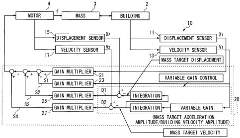
Next, a vibration control device 10 of the present
embodiment will be described with reference to Figure 2.
In the following description, it is assumed that the
vibration control device 10 is applied to the modeled
controlled object including the building 2 and the
movable mass 3 illustrated in Figure 1.
The vibration control device 10 includes a building
displacement sensor 11 and a building velocity sensor 13
attached on the building 2. The building displacement
sensor 11 detects the amount of a horizontal displacement
of the building 2 (building displacement x1), and the
building velocity sensor 13 detects a horizontal velocity
of the building 2 (building velocity vl (first-order
differentiation of x1))=
2013301CA
CA 02898093 2015-07-13
1
- 12 -
The vibration control device 10 also includes a mass
displacement sensor 15 and a mass velocity sensor 17
attached to a motor (actuator) 4 that drives the movable
mass 3 disposed on a top portion of the building 2. The
mass displacement sensor 15 detects the amount of a
horizontal displacement of the movable mass 3 (mass
displacement x2) from the behavior of the motor 4, and
the mass velocity sensor 17 detects a horizontal velocity
of the movable mass 3 (mass velocity v2 (first-order
differentiation of x2)) from the behavior of the motor 4.
Because velocity can be obtained by performing time
differentiation of displacement, the building velocity vl
and the mass velocity v2 can be calculated on the basis
of a detection result of the displacement sensor instead
of relying on the velocity sensor. Likewise, the
building displacement xl and the mass displacement x2 can
be calculated on the basis of a detection result of the
velocity sensor instead of relying on the displacement
sensor. Thus, although an example of disposing a
displacement sensor and a velocity sensor is described
herein, the present embodiment can be achieved with
either a displacement sensor or a velocity sensor.
The vibration control device 10 includes a
controller 20. The controller 20 includes a first gain
multiplier 21 that outputs a signal Si obtained by
multiplying the building displacement xl by a control
gain Kdl, a second gain multiplier 23 that outputs a
2013301CA
CA 02898093 2015-07-13
- 13 -
signal S2 obtained by multiplying the building velocity
vl by a control gain Kd2, a third gain multiplier 25 that
outputs a signal S3 obtained by multiplying a deviation
D10 between the mass displacement x2 and a target
displacement of the movable mass 3 by a control gain Kd3,
and a fourth gain multiplier 27 that outputs a signal S4
obtained by multiplying a deviation D20 between the mass
velocity v2 and a target velocity of the movable mass 3
by a control gain Kd4. As described above, the target
velocity of the movable mass 3 is a value obtained by
performing first-order integration of equation (6), and
the target displacement of the movable mass 3 is a value
obtained by performing second-order integration of
equation (6). In the controller 20, the step
corresponding to the above-described equation (7) is
executed in the portion labeled as "variable gain".
The control gains Kdl to Kd4 are calculated in
accordance with an optimum control theory, for example,
and are meant to be constants that are arbitrarily set.
The controller 20 sums the signal S1 from the first
gain multiplier 21, the signal S2 from the second gain
multiplier 23, the signal 53 from the third gain
multiplier 25, and the signal S4 from the fourth gain
multiplier 27. The controller 20 gives the sum to the
motor 4 as a control command for the control force f
applied to the movable mass 3.
2013301CA
CA 02898093 2015-07-13
- 14 -
Here, another control logic (comparison logic) could
be established in which a signal S3' obtained by
multiplying the mass displacement x2 by the control gain
Kd3 and a signal S4' obtained by multiplying the mass
velocity v2 by the control gain Kd4 are summed to the
above-described signals Si and S2. This control logic is
based on the assumption that the targets of the
displacement and the velocity of the movable mass are
made to zero. The control logic of the present embodiment,
on the other hand, further includes the variable gain
control, as described above. Thus, instead of making the
targets of the displacement and the velocity of the
movable mass 3 to zero, the movement that enhances the
damping of the vibration of the building 2, which is a
vibration-controlled structure, is adopted as target
values.
As described above, according to the vibration
control device 10, the target displacement and the target
velocity are calculated using the variable control gain a
such that the amplitude of the movable mass 3 becomes
constant not only when the building 2 vibrates due to
winds but also when the building 2 vibrates rapidly due
to earthquakes. Thus, the best vibration control effect
can be efficiently and reliably achieved within the
allowable stroke range of the movable mass 3. Also,
according to the present embodiment, the vibration
control effect for earthquakes can be effectively
2013301CA
CA 02898093 2015-07-13
,
,
- 15 -
obtained by simply changing control software without
building a new device.
Simulations have been conducted for checking the
vibration control effect for the building 2 under an
earthquake by using the comparison logic and the logic of
the present embodiment. Figure 3 shows the results of
the simulations. According to the present embodiment,
while the comparison active logic permits the movable
mass 3 to vibrate beyond the allowable stroke range, in
the present invention the vibration of the movable mass 3
includes a constant portion and is maintained within the
allowable stroke range.
[Second to Fourth Embodiments]
In the first embodiment, the variable control gain a
is calculated by dividing the target acceleration of the
movable mass 3 by the velocity amplitude of the building
2, as shown in equation (7). The variable control gain a
is, however, not limited to the above calculation, as
long as the phase relationship indicated in equation (4),
or the condition that the mass displacement x2 is phase-
delayed 90 degrees with respect to the building
displacement xl, is satisfied. For example, the
following (b), (c), and (d) are combinations that satisfy
the phase relationship of equation (4). The (b), (c),
and (d) correspond to equations (6) and (7). The (a)
corresponds to the above-described first embodiment.
Figures 4, 5 and 6 illustrate control logics based on the
2013301CA
CA 02898093 2015-07-13
- 16 ¨
following (b) , (c) , and (d) . In these figures, the same
components as those of Figure 2 are indicated with the
same numerals. In the following description of Figures 4,
5, and 6, the differences from the first embodiment will
be mainly described.
[Expression 7]
==
(a) x = a x a= mass target acceleration amplitude/building velocity amplitude
(first embodiment)
(b) X2= a
a= mass target velocity amplitude/building displacement amplitude (second
embodiment)
xi,
(c) x2= --ct a= mass target displacement amplitude/building velocity
amplitude (third embodiment)
(d) ;=¨a x a= mass target velocity amplitude/building acceleration amplitude
(fourth embodiment)
[Second Embodiment]
In a second embodiment, a is calculated by dividing
the target velocity amplitude of the movable mass 3 by
the amplitude of the displacement waveform (hereinafter
referred to as displacement amplitude) of the building 2.
Thus, a changes in accordance with the displacement
amplitude of the building 2 that is sequentially detected.
As with the first embodiment, the mass displacement can
be maintained within a constant range regardless of the
vibration of the building 2. This is also true of
embodiments 3 and 4.
As illustrated in Figure 4, in the second embodiment,
a value obtained by performing first-order integration of
the variable gain obtained with the above (b) (first-
order differentiation of the displacement x2 of the
movable mass 3) is used as a target displacement of the
movable mass 3.
2013301CA
CA 02898093 2015-07-13
i
4
- 17 -
In the second embodiment, the third gain multiplier
25 outputs a signal S31 obtained by multiplying a
deviation Dll between the mass displacement x2 and the
target displacement of the movable mass 3 by a control
gain Kd31, and the fourth gain multiplier 27 outputs a
signal S41 obtained by multiplying a deviation D21
between the mass velocity v2 and the target velocity of
the movable mass 3 by a control gain Kd41. The first
gain multiplier 21 and the second gain multiplier 23 are
the same as those of the first embodiment.
In the second embodiment, the signal Si from the
first gain multiplier 21, the signal S2 from the second
gain multiplier 23, the signal S31 from the third gain
multiplier 25, and the signal S41 from the fourth gain
multiplier 27 are summed. The sum is given to the motor
4 as a control command for the control force f applied to
the movable mass 3.
[Third Embodiment]
In the third embodiment, a is calculated by dividing
the target displacement amplitude of the movable mass 3
by the velocity amplitude of the building 2. Thus, a
changes in accordance with the velocity amplitude of the
building 2 that is sequentially detected.
As illustrated in Figure 5, in the third embodiment,
a value obtained by performing first-order integration of
the variable gain obtained with the above (c) (the mass
2013301CA
CA 02898093 2015-07-13
t
4
- 18 -
displacement x2 of the movable mass 3) is used as a
target velocity of the movable mass 3.
The (c) indicates that, if the relationship
(equation (4)) in which the mass displacement x2 is
phase-delayed 90 degrees with respect to the building
displacement xl is represented with the building velocity
and the mass displacement, then the sign inversion of the
building velocity has a phase which proceeds 90 degrees
with respect to the mass displacement.
In the third embodiment, the third gain multiplier
25 outputs a signal S32 obtained by multiplying a
deviation D12 between the mass displacement x2 and the
target displacement of the movable mass 3 by a control
gain Kd32, and the fourth gain multiplier 27 outputs a
signal S42 obtained by multiplying a deviation D22
between the mass velocity v2 and the target velocity of
the movable mass 3 by a control gain Kd42. The first
gain multiplier 21 and the second gain multiplier 23 are
the same as those of the first embodiment.
In the third embodiment, the signal Si from the
first gain multiplier 21, the signal 52 from the second
gain multiplier 23, the signal S32 from the third gain
multiplier 25, and the signal S42 from the fourth gain
multiplier 27 are summed. The sum is given to the motor
4 as a control command S for the control force f applied
to the movable mass 3.
[Fourth Embodiment]
2013301CA
CA 02898093 2015-07-13
4
- 19 -
The fourth embodiment includes a building
acceleration sensor 14 for detecting a horizontal
acceleration of the building 2.
Also, in the fourth embodiment, a is calculated by
dividing a target velocity amplitude value of the movable
mass 3 by the amplitude of the acceleration waveform
(hereinafter referred to as acceleration amplitude) of
the building 2. Thus, a changes in accordance with the
acceleration amplitude of the building 2 that is
sequentially detected.
As illustrated in Figure 6, in the fourth embodiment,
a value obtained by performing first-order integration of
the variable gain obtained with the above (d) (first-
order differentiation of the displacement x2 of the
movable mass 3) is used as a target displacement of the
movable mass 3.
In the fourth embodiment, the third gain multiplier
25 outputs a signal S33 obtained by multiplying a
deviation D13 between the mass displacement x2 and the
target displacement of the movable mass 3 by a control
gain Kd33, and the fourth gain multiplier 27 outputs a
signal S43 obtained by multiplying a deviation D23
between the mass velocity v2 and the target velocity of
the movable mass 3 by a control gain Kd43. The first
gain multiplier 21 and the second gain multiplier 23 are
the same as those of the first embodiment.
2013301CA
1
CA 02898093 2015-07-13
- 20 -
The signal S1 from the first gain multiplier 21, the
signal S2 from the second gain multiplier 23, the signal
S33 from the third gain multiplier 25, and the signal S43
from the fourth gain multiplier 27 are summed. The sum
is given to the motor 4 as the control command S for the
control force f applied to the movable mass 3.
As described in the above description of the second
to fourth embodiments, it is only necessary to specify a
target value for either the displacement or the velocity
of the movable mass 3. This means that the control
method of the present invention can be utilized
regardless of the type of sensors used, and it is
possible to cut the cost of adding or re-installing
sensors.
In order to obtain a vibration control effect more
reliably, however, it is preferable to specify a target
value for both the displacement and the velocity, as with
the first embodiment.
In the first to fourth embodiments, if arithmetic
operation such as differentiation and integration is used
in an installed sensor, it is desirable to choose a
combination in which the operation exerts a smaller
influence.
Although the present invention has been described in
accordance with the embodiments, it is possible to choose
any of the configurations described in the above
embodiments or arbitrarily change to another
2013301CA
CA 02898093 2015-07-13
- 21 -
configuration, as long as they do not depart from the
gist of the present invention.
For example, in the above embodiments, although an
example is described in which the phase delay is 90
degrees, which is most preferable, the present invention
is not limited to this. Because the phase delay larger
than 0 degrees and less than 180 degrees contributes to
damping, it is possible in the present invention to
choose any angle of phase delay within this range.
However, the further the phase delay gets away from the
most preferable 90 degrees, the more the damping
performance decreases. Therefore, the phase delay is
preferably plus or minus 20 degrees, more preferably plus
or minus 10 degrees, and still more preferably plus and
minus 5 degrees from 90 degrees.
Reference Signs List
1 ground
2 building
3 movable mass
4 motor
vibration control device
controller
11 building displacement sensor
13 building velocity sensor
14 building acceleration sensor
15 mass displacement sensor
2013301CA
1
CA 02898093 2015-07-13
- 22 -
17 mass velocity sensor
21 first gain multiplier
23 second gain multiplier
25 third gain multiplier
27 fourth gain multiplier
2013301CA