Note: Descriptions are shown in the official language in which they were submitted.
CA 02898323 2015-07-15
FLUID APPLICATION DEVICE
BACKGROUND INFORMATION
1. Field:
The present disclosure relates generally to applying fluid onto a surface and,
in particular, to applying fluid onto a surface using an applicator. Still
more
particularly, the present disclosure relates to a method and apparatus for
dispensing
a fluid from a fluid source to the applicator while applying the fluid onto a
surface
using the applicator.
2. Background:
In some cases, during the manufacturing process, a fluid may need to be
applied over a surface. The fluid may be, for example, without limitation, a
sealant,
a paste, a type of paint, an adhesive, or some other type of fluid.
Oftentimes,
brushes may be used to apply these fluids over a surface.
As one illustrative example, a brush may be dipped into a container holding a
fluid, such as, for example, without limitation, a sealant. The container may
be, for
example, without limitation, a cup, a can, a tank, or some other type of
container.
Dipping the brush into the sealant in the container may allow some of the
sealant to
be retained by the bristles of the brush. After the brush is dipped into the
sealant
within the container, the brush may be used to manually apply the sealant onto
a
surface. In other words, the brush may be used to brush the sealant onto the
surface.
As the sealant is applied onto the surface, the amount of sealant retained by
the brush may decrease. Consequently, the brush may need to be re-dipped into
the sealant in the container. When the area of the surface over which the
sealant is
to be applied is large, the process of re-dipping the brush between
applications of
the sealant onto the surface may need to be performed multiple times. This
type of
process may be more time-consuming than desired. Further, with this type of
1
process, the amount of sealant used may exceed the actual amount of sealant
that
was needed. Therefore, it would be desirable to have a method and apparatus
that
take into account at least some of the issues discussed above, as well as
possibly
other issues.
SUMMARY
In one embodiment, there is provided an apparatus including: a platform
affixed to a robot; an extension member rotatably connected to the platform;
an
applicator associated with a fluid source and connected to the extension
member; a
first movement system associated with the robot; a second movement system
located
inside the platform and configured to rotate the applicator independently of
the
extension member about a first axis through the applicator, for applying fluid
from the
fluid source to a surface; and a third movement system located inside the
platform
and configured to rotate the extension member and the applicator about a
second
axis.
The second axis may be an extension axis through the extension member.
The first axis may be different from the second axis.
The first movement system is configured to move the robot to move the
applicator to a position over the surface.
The second movement system may include a number of motors, a number of
shafts, a number of belt systems, and a number of gears.
The second movement system may include a second movement system motor
and a pulley.
The second movement system may be further configured to rotate the
applicator about the first axis without rotating the platform.
The third movement system may include a number of motors, a number of
shafts, and a number of gears.
2
CA 2898323 2019-01-21
The third movement system may include a third movement system motor, a
first gear and a second gear.
The third movement system may be further configured to rotate the extension
member and the applicator about the second axis without rotating the platform.
The apparatus may further include an applicator coupling unit configured to
couple the applicator to the extension member.
The applicator may be a brush and the fluid may be a sealant.
The fluid source may be a cartridge.
The cartridge may be associated with the platform and the applicator may be
configured to receive the fluid dispensed by the cartridge.
The extension member may be a telescopic arm configured to extend and
=
retract with respect to an arm axis through the telescopic arm.
The apparatus may further include a fluid control system configured to control
at least one of an amount of the fluid and a rate of the fluid dispensed to
the
applicator.
The fluid control system may include at least one of a hose, a valve system,
and a nozzle.
The extension member may be configured to maintain a selected distance
between the applicator and the fluid source.
The extension member may allow the applicator to be positioned within an
area in which the fluid source does not fit.
The extension member with the applicator may be configured for being
inserted into an opening through which the fluid source does not fit.
The apparatus may further include a platform attachment unit configured for
use in attaching the platform to the robot.
The apparatus may further include an extension member attachment unit
configured for use in attaching the extension member to the platform.
3
CA 2898323 2019-01-21
The extension member may angularly offset the applicator from the platform by
a selected distance.
The platform may be fixedly affixed to the robot.
At least a portion of the second movement system may be located inside the
extension member.
At least a portion of the third movement system may be located inside the
extension member.
The robot may include a robotic arm.
In another embodiment, there is provided an end effector including: a
platform;
an extension member rotatably connected to the platform; a cartridge
associated with
the platform and configured to dispense a sealant; and an applicator
associated with
the extension member such that a selected distance is maintained between the
applicator and the cartridge. The applicator is configured to receive the
sealant
dispensed by the cartridge and the applicator is configured for use in
applying the
sealant onto a surface. The end effector further includes an attachment unit
configured to attach the platform to a robotic operator. The robotic operator
is
configured to move at least one of the platform and the extension member to
position
the applicator over the surface. The end effector further includes a first
movement
system of the robotic operator; a second movement system located inside the
extension member and the platform and configured to rotate the applicator
independently of the extension member about a first axis through the
applicator for
applying the sealant to the surface; and a third movement system located
inside the
extension member and the platform and configured to rotate the extension
member
and the applicator about a second axis.
The second axis may be an extension axis through the extension member.
In another embodiment, there is provided a fluid application device including:
a
platform affixed to a robot; a cartridge associated with the platform and
configured to
4
CA 2898323 2019-01-21
dispense a sealant; an extension member associated with the platform and
configured to extend from the platform; and a brush associated with the
extension
member and configured to receive the sealant dispensed by the cartridge. The
brush
is configured for use in applying the sealant onto a surface. The fluid
application
device further includes a fluid control system configured to control at least
one of an
amount of the sealant and a rate of the sealant dispensed to the brush. The
fluid
control system includes at least one of a hose, a valve system, and a nozzle.
The
fluid application device further includes an applicator movement system
configured to
move the brush. The applicator movement system includes: a first movement
system
- associated with the robot and configured to position the brush over the
surface; and a
second movement system located inside the platform and configured to rotate
the
brush independently of the extension member about a first axis through the
brush for
applying the sealant to the surface. The second movement system includes a
number
of motors, a number of shafts, a number of belt systems, and a number of
gears. The
applicator movement system further includes: a third movement system located
inside
the platform and configured to rotate the extension member and the applicator
about
a second axis. The third movement system includes a number of motors, a number
of
shafts, and a number of gears. The fluid application device further includes
an
applicator coupling unit configured to couple the brush to the extension
member.
The second movement system may be configured to rotate the brush about the
first axis without rotating the platform.
At least a portion of the second movement system may be located inside the
extension member.
The third movement system may be configured to rotate the extension member
and the brush about the second axis without rotating the platform.
At least a portion of the third movement system may be located inside the
extension member.
CA 2898323 2019-01-21
The first axis may be different from the second axis.
The robot may include a robotic arm.
In another embodiment, there is provided a method for applying a viscous fluid
onto a surface. The method involves causing a first movement system to move a
robot to position an applicator over the surface. The applicator is associated
with an
extension member coupled to a platform affixed to the robot. The method
further
involves: causing a second movement system located inside the platform to
rotate the
applicator independently of the extension member about a first axis through
the
applicator for applying the viscous fluid to the surface; causing a third
movement
system located inside the platform to rotate the extension member and the
applicator
about a second axis; dispensing the viscous fluid from a fluid source to the
applicator;
and applying the viscous fluid onto the surface using the applicator.
Causing the first movement system to move the robot to position the applicator
over the surface may involve causing the first movement system to move at
least one
of the extension member and the platform.
The fluid source may be associated with the platform.
The method may further involve controlling at least one of an amount of the
viscous fluid and a rate of the viscous fluid dispensed from the fluid source
to the
applicator using a fluid control system.
Applying the viscous fluid onto the surface using the applicator may involve
applying the viscous fluid onto the surface using the applicator to seal a
number of
interfaces on the surface. The viscous fluid may be a sealant and the
applicator may
be a brush.
The second axis may be an extension member axis through the extension
member.
The method may further involve extending the applicator away from the
platform by telescopically extending the extension member, relative to the
platform.
6
CA 2898323 2019-01-21
Telescopically extending the extension member may involve telescopically
extending the extension member along an extension member axis through the
_ extension member.
Causing the first movement system to move the robot to position the applicator
over the surface may involve causing the first movement system to move the
robot to
position the platform. The platform may be attached to the robot by an
attachment
unit.
Dispensing the viscous fluid from the fluid source to the applicator may
involve
dispensing the viscous fluid having a viscosity between 50 poise and 12,500
poise.
The robot may include a robotic arm.
In another embodiment, there is provided a method for applying a sealant onto
a surface. The method involves positioning a platform over the surface using a
first
movement system associated with a robot. The platform is attached to the robot
by an
attachment unit. Positioning the platform positions an extension member
associated
with the platform. The method further involves: dispensing the sealant from a
cartridge associated with the platform to an applicator associated with the
extension
member; controlling at least one of an amount of the sealant and a rate of the
sealant
dispensed from the cartridge to the applicator using a fluid control system;
rotating the
applicator independently of the extension member about a first axis through
the
applicator using a second movement system; and rotating the extension member
about a second axis through the extension member using a third movement
system.
Rotation of the extension member causes rotation of the applicator about the
second
axis. The method further involves applying the sealant onto the surface using
the
applicator to seal a number of interfaces on the surface.
In another embodiment, there is provided a method for applying a sealant onto
- a plurality of fasteners installed in a structure. The method involves:
moving an
applicator associated with an extension member in a fluid application device
to an
7
CA 2898323 2019-01-21
initial position over a fastener in the plurality of fasteners using a first
movement
system. Moving the applicator further involves rotating the extension member
about
an extension member axis through the extension member using an extension
member movement system. Rotation of the extension member causes rotation of
the
applicator about the extension member axis. The method further involves:
rotating the
. applicator independently of the extension member about an applicator axis
through
the applicator using a second movement system; dispensing a controlled amount
of
the sealant from a cartridge held by a platform associated with the extension
member
to the applicator at a controlled rate while the applicator is rotating about
the
applicator axis; and applying the sealant onto the fastener using the
applicator
according to a predefined application routine.
The method may further involve: stopping a flow of the sealant to the
applicator; stopping rotation of the applicator about the applicator axis;
moving the
applicator to a next fastener in the plurality of fasteners using the robotic
first
movement system; and repeating the steps of rotating the applicator about the
applicator axis using the second movement system, dispensing the controlled
amount
of the sealant from the cartridge to the applicator at the controlled rate
while the
applicator is rotating about the applicator axis, and applying the sealant
onto the
fastener using the applicator according to the predefined application routine
for the
next fastener.
Moving the applicator may further involve moving at least one of the extension
member and the platform using the first movement system to move the
applicator.
Applying the sealant onto the fastener using the applicator according to the
predefined application routine may involve repeating rotating the extension
member
about the extension member axis using the extension member movement system
such that the applicator is rotated about the extension member axis while the
sealant
is being applied onto the fastener.
8
CA 2898323 2019-01-21
The first movement system may include a movement system associated with a
robot. The platform may be affixed to the robot.
The robot may include a robotic arm.
In another embodiment, there is provided an end effector apparatus for
attachment to a robot. The apparatus includes: a platform configured for
attachment
to the robot; a fluid source associated with the platform and configured to
dispense a
fluid; an extension member associated with the platform and configured to
extend
from the platform; and an applicator associated with the extension member. The
applicator is configured to receive the fluid dispensed by the fluid source
and is
configured for use in applying the fluid onto a surface. The apparatus further
includes
an applicator movement system configured to move the applicator. The
applicator
movement system is configured to rotate the applicator about an applicator
axis
through the applicator independently of the extension member. The applicator
is a
brush and the fluid is a sealant.
The applicator movement system may further include an extension member
movement system configured to rotate the extension member about an extension
member axis through the extension member. Rotation of the extension member may
cause rotation of the applicator about the extension member axis.
The extension member movement system may be operable to move the
applicator to a position over the surface.
The extension member movement system may include at least one of a
number of motors, a number of shafts, a number of belt systems, and a number
of
gears.
The applicator movement system may include at least one of a number of
motors, a number of shafts, a number of belt systems, and a number of gears.
The apparatus may further include an applicator coupling unit configured to
couple the applicator to the extension member.
9
CA 2898323 2019-01-21
The fluid source may include a cartridge configured to be held and supported
by the platform.
The extension member may include a telescopic arm configured to extend and
retract with respect to an arm axis through the telescopic arm.
The apparatus may further include a fluid control system configured to control
at least one of an amount of the fluid and a rate of the fluid dispensed to
the
applicator.
The fluid control system may include at least one of a hose, a valve system,
and a nozzle.
The extension member may be configured to maintain a selected distance
between the applicator and the fluid source.
The extension member may allow the applicator to be positioned within an
area in which the fluid source does not fit.
The extension member with the applicator may be configured for being
inserted into an opening through which the fluid source does not fit.
The apparatus may further include an attachment unit configured for
association with the platform. The attachment unit may be configured for use
in
attaching the platform to the robot.
The apparatus may further include an attachment unit configured for
association with the extension member. The attachment unit may be configured
for
use in attaching the extension member to the robot.
The robot may include a robotic arm.
The features and functions can be achieved independently in various
embodiments of the present disclosure or may be combined in yet other
embodiments in which further details can be seen with reference to the
following
description and drawings.
CA 2898323 2019-01-21
CA 02898323 2015-07-15
BRIEF DESCRIPTION OF THE DRAWINGS
The novel features believed characteristic of the illustrative embodiments are
set forth in the appended claims. The illustrative embodiments, however, as
well as
a preferred mode of use, further objectives and features thereof, will best be
understood by reference to the following detailed description of an
illustrative
embodiment of the present disclosure when read in conjunction with the
accompanying drawings, wherein:
Figure 1 is an illustration of a fluid application device in the form of a
block
diagram in accordance with an illustrative embodiment;
Figure 2 is an illustration of an isometric view of a fluid application device
in
accordance with an illustrative embodiment;
Figure 3 is an illustration of a cross-sectional view of a fluid application
device in accordance with an illustrative embodiment;
Figure 4 is an illustration of an isometric view of a different implementation
for
a fluid application device in accordance with an illustrative embodiment;
Figure 5 is an illustration of an isometric view of a fluid application device
in
accordance with an illustrative embodiment;
Figure 6 is an illustration of a cross-sectional view of a fluid application
device in accordance with an illustrative embodiment;
Figure 7 is another illustration of a cross-sectional view of a fluid
application
device in accordance with an illustrative embodiment;
Figure 8 is yet another illustration of a cross-sectional view of a fluid
application device in accordance with an illustrative embodiment;
Figure 9 is an illustration of a view of a turning mechanism in accordance
with an illustrative embodiment;
Figure 10 is an illustration of a fluid application device in accordance with
an
illustrative embodiment;
Figure 11 is an illustration of a cross-sectional view of a fluid application
device in accordance with an illustrative embodiment;
11
CA 02898323 2015-07-15
Figure 12 is an illustration of a view of a fluid application device in
accordance with an illustrative embodiment;
Figure 13 is an illustration of a process for applying a fluid onto a surface
in
the form of a flowchart in accordance with an illustrative embodiment;
Figure 14 is an illustration of a process for applying a sealant onto a
surface
in the form of a flowchart in accordance with an illustrative embodiment;
Figure 15 is an illustration of a process for applying a sealant onto a
plurality
of fasteners in the form of a flowchart;
Figure 16 is an illustration of an aircraft manufacturing and service method
in
the form of a flowchart in accordance with an illustrative embodiment; and
Figure 17 is an illustration of an aircraft in the form of a block diagram in
accordance with an illustrative embodiment.
DETAILED DESCRIPTION
Referring now to the figures and, in particular, with reference to Figure 1,
an
illustration of a fluid application device is depicted in the form of a block
diagram in
accordance with an illustrative embodiment. In this illustrative example,
fluid
application device 100 may be used to apply fluid 102 onto surface 104.
Fluid application device 100 may be operated by human operator 106 or
robotic operator 108. For example, robotic operator 108 may be configured to
operate fluid application device 100 and move fluid application device 100. In
particular, robotic operator 108 may be used to position fluid application
device 100
relative to surface 104 and/or move fluid application device 100 over surface
104.
In one illustrative example, robotic operator 108 comprises robotic arm 110.
In this example, fluid application device 100 may take the form of end
effector 112
configured for attachment to robotic arm 110.
As depicted, fluid application device 100 may include platform 114, fluid
source 116, extension member 117, applicator 120, fluid control system 122,
12
CA 02898323 2015-07-15
applicator movement system 124, and attachment unit 125. Attachment unit 125
may be configured to attach end effector 112 to robotic arm 110.
Platform 114 may be comprised of one or more structures configured to hold
and support the various components of fluid application device 100. Depending
on
the implementation, one or more of fluid source 116, extension member 117,
fluid
control system 122, applicator movement system 124, and attachment unit 125
may
be associated with platform 114. In some illustrative examples, attachment
unit 125
may be associated with extension member 117.
When one component is "associated" with another component, as used
herein, this association is a physical association in the depicted examples.
For
example, a first component, such as fluid source 116, may be considered to be
associated with a second component, such as platform 114, by being secured to
the
second component, bonded to the second component, mounted to the second
component, welded to the second component, fastened to the second component,
and/or connected to the second component in some other suitable manner. In
some
cases, the first component may be considered associated with the second
component by being connected to the second component by a third component.
The first component also may be considered to be associated with the second
component by being formed as part of and/or as an extension of the second
component.
Fluid source 116 is configured to hold, or store, fluid 102. In this
illustrative
example, fluid source 116 may take the form of cartridge 126. However, in
other
illustrative examples, fluid source 116 may take some other form such as, for
example, without limitation, a container, a tank, a reservoir, a casing, or
some other
type of storage structure.
In this illustrative example, fluid 102 held by cartridge 126 may be viscous
fluid 128. As used herein, a "viscous" fluid may be a fluid that resists shear
flow and
strain linearly with time when a stress is applied. Viscous fluids may be
considered
as having a thick consistency. Viscous fluid 128 may have a viscosity between
about 50 poise and about 12,500 poise in some illustrative examples. Of
course, in
13
CA 02898323 2015-07-15
other illustrative examples, viscous fluid 128 may have a viscosity less than
about 50
poise or greater than about 12,500 poise.
In one illustrative example, viscous fluid 128 takes the form of sealant 130.
Of course, in other illustrative examples, viscous fluid 128 may take the form
of an
adhesive. When viscous fluid 128 takes the form of sealant 130, fluid
application
device 100 may be referred to as a "sealant application device."
Sealant 130 may be applied onto surface 104 to, for example, without
limitation, seal number of interfaces 131 on surface 104. As used herein, a
"number
of" items may be one or more items. For example, number of interfaces 131 may
include one or more interfaces. An "interface," such as one of number of
interfaces
131, as used herein, may be an interface between any two objects. For example,
an
interface may be the boundary between two objects that have been joined
together.
An interface may be the boundary between a fastener element and the object
into
which the fastener element has been installed.
Fluid 102 may be dispensed from fluid source 116 to applicator 120 using
fluid control system 122. Fluid control system 122 may be configured to
control the
flow of fluid 102 from fluid source 116 to applicator 120. Fluid control
system 122
may include at least one of hose 132, valve system 134, nozzle 136, and some
other
type of fluid transport element or flow control element.
As used herein, the phrase "at least one of," when used with a list of items,
may mean that different combinations of one or more of the listed items may be
used. In some cases, only one item in the list of items may be needed. For
example, "at least one of item A, item B, and item C" may include item A; item
A and
item B; item A, item B, and item C; item B and item C; or some other type of
combination. As another example, "at least one of item A, item B, and item C"
may
include, but is not limited to, two of item A, one of item B, and ten of item
C; four of
item B and seven of item C; or some other type of combination. The item may be
a
particular object, thing, or a category. In other words, at least one of means
any
combination items and number of items may be used from the list but not all of
the
items in the list are required.
14
CA 02898323 2015-07-15
Hose 132 may be attached to fluid source 116 such that hose 132 is
configured to receive fluid 102 dispensed by fluid source 116. The flow of
fluid 102
from hose 132 to applicator 120 may be controlled using valve system 134
and/or
nozzle 136. Valve system 134 may include, for example, without limitation, at
least
one of number of valves 138 and number of actuators 140. In one illustrative
example, valve system 134 may be used to control amount 142 of fluid 102 sent
to
applicator 120, while nozzle 136 may be used to control rate 144 at which
fluid 102
is sent to applicator 120. In this manner, a controlled amount 142 of fluid
102 may
be dispensed, or supplied, to applicator 120 at a controlled rate 144.
As depicted, extension member 117 may be associated with end 146 of
platform 114. In particular, extension member 117 may extend from end 146 of
platform 114. In this illustrative example, extension member 117 may take the
form
of arm 118. However, in other illustrative examples, extension member 117 may
take some other form.
Extension member 117 allows applicator 120 to be extended away from fluid
source 116 such that fluid source 116 and applicator 120 are not co-located
together. More specifically, extension member 117 may be configured to
maintain a
selected distance between fluid source 116 and applicator 120. In this manner,
extension member 117 may allow applicator 120 to be positioned within an area
in
which fluid source 116 does not fit. The area may be, for example, a
compartment,
a hollow portion of a tube, an interior of a structure, a confined area, or
some
otherwise difficult-to-reach area. For example, without limitation, extension
member
117 may have a size configured such that extension member 117 and applicator
120
may be inserted into an opening in a structure through which fluid source 116
does
not fit.
Applicator 120 may be associated with arm 118. Applicator 120 may take the
form of any type of device or tool configured for use in applying fluid 102
onto
surface 104. As one illustrative example, applicator 120 may take the form of
brush
148. Brush 148 may have bristles 150 configured for use in applying fluid 102
onto
surface 104.
CA 02898323 2015-07-15
In one illustrative example, applicator coupling unit 152 may be used to
couple applicator 120 to arm 118. Applicator coupling unit 152 may comprise
any
number of structures, fasteners, and/or other components needed to couple
applicator 120 to arm 118. In this illustrative example, applicator coupling
unit 152
may couple applicator 120 to arm 118 in a manner that allows applicator 120 to
move independently of at least one of applicator coupling unit 152 and arm
118.
Applicator 120 may be moved using applicator movement system 124.
Applicator movement system 124 may include at least one of first movement
system
154 and second movement system 156. First movement system 154 may be
configured to rotate applicator 120 about applicator axis 158. Applicator axis
158
may be a center axis through applicator 120 in one illustrative example.
Applicator
120 may be rotated independently of applicator coupling unit 152 and/or arm
118.
As depicted, first movement system 154 may include, for example, without
limitation, at least one of number of motors 160, number of shafts 162, number
of
belt systems 164, and some other type of movement device or element. Belt
system
166 may be an example of one of number of belt systems 164. In one
illustrative
example, belt system 166 may be used to rotate applicator 120 about applicator
axis
158.
Belt system 166 may include, for example, without limitation, first pulley
168,
second pulley 170, and belt 172. Belt 172 may wrap around both first pulley
168
and second pulley 170. First pulley 168 may be connected to one of number of
motors 160 by one of number of shafts 162. Operation of this motor may cause
rotation of first pulley 168 in a direction around applicator axis 158, which
may, in
turn, cause movement of belt 172. Movement of belt 172 may then cause rotation
of
second pulley 170 in the same direction around applicator axis 158. For
example,
clockwise rotation of first pulley 168 may result in clockwise rotation of
second pulley
170.
Second pulley 170 may be connected to applicator 120 by another one of
number of shafts 162 or in some other manner. Rotation of second pulley 170 in
a
direction around applicator axis 158 may cause rotation of applicator 120
about
16
CA 02898323 2015-07-15
applicator axis 158. For example, clockwise rotation of second pulley 170 may
lead
to clockwise rotation of applicator 120 about applicator axis 158. In this
manner, first
movement system 154 may be configured to move rotate applicator 120 about
applicator axis 158. Of course, any configuration of number of motors 160,
number
of shafts 162, and/or number of belt systems 164 may be used to rotate
applicator
120.
Second movement system 156 may also be configured to move applicator
120. In particular, second movement system 156 may be configured to rotate arm
118 about an axis through arm 118, which may be referred to as arm axis 174.
Arm
axis 174 may be a longitudinal axis through arm 118. In one illustrative
example,
arm axis 174 may be substantially perpendicular to applicator axis 158.
However, in
other illustrative examples, applicator 120 may be coupled to arm 118 in such
a
manner that arm axis 174 is at some other angle relative to applicator axis
158.
When arm 118 rotates about arm axis 174, applicator 120 may be moved
along with arm 118. In this manner, the coupling of applicator 120 to arm 118
may
be configured such that movement of arm 118 causes the same movement of
applicator 120 but movement of applicator 120 may not cause the same movement
of arm 118.
Second movement system 156 may include, for example, without limitation, at
least one of number of motors 176, number of shafts 178, number of gears 180,
number of belt systems 182, and some other type of movement device or element.
One or more of number of belt systems 182 may be implemented in a manner
similar to the implementation of belt system 166. In some cases, second
movement
system 156 may be configured to restrict the range of rotation of arm 118
about arm
axis 174. In other illustrative examples, second movement system 156 may be
configured to allow arm 118 to fully rotate about 360 degrees about arm axis
174.
Of course, depending on the implementation, first movement system 154
and/or second movement system 156 may be implemented in some other manner
than described. For example, first movement system 154 and/or second movement
system 156 may be implemented using a number of actuators, a number of slip
17
CA 02898323 2015-07-15
rings, a number of wheels, a number of gears, and/or any number of other types
of
components. The actuators used may be selected from, for example, without
limitation, linear actuators, rotary actuators, shape-memory alloy actuators,
electromechanical actuators, hydraulic actuators, pneumatic actuators, and/or
other
types of actuators.
The illustration of fluid application device 100 in Figure 1 is not meant to
imply physical or architectural limitations to the manner in which an
illustrative
embodiment may be implemented. Other components in addition to or in place of
the ones illustrated may be used. Some components may be optional. Also, the
blocks are presented to illustrate some functional components. One or more of
these blocks may be combined, divided, or combined and divided into different
blocks when implemented in an illustrative embodiment.
With reference now to Figure 2, an illustration of an isometric view of a
fluid
application device is depicted in accordance with an illustrative embodiment.
In this
illustrative example, fluid application device 200 may be an example of one
implementation for fluid application device 100 in Figure 1.
Fluid application device 200 may be used to apply sealant 202 onto surface
204. Sealant 202 may be an example of one implementation for sealant 130 in
Figure 1. Surface 204 may be an example of one implementation for surface 104
in
Figure 1.
As depicted, surface 204 may include a portion of surface 206 of object 205
and a portion of surface 208 of object 207. Object 205 and object 207 have
been
joined using bracket 210. Fluid application device 200 may apply sealant 202
over
surface 204 to seal interface 212 formed between object 205 and object 207
using
bracket 210. Interface 212 may be an example of one implementation for one of
number of interfaces 131 in Figure 1.
In this illustrative example, fluid application device 200 may include
platform
214, cartridge 216, arm 218, brush 220, fluid control system 222, and
applicator
movement system 224. Platform 214, cartridge 216, arm 218, brush 220, fluid
control system 222, and applicator movement system 224 may be examples of
18
CA 02898323 2015-07-15
implementations for platform 114, cartridge 126, arm 118, brush 148, fluid
control
system 122, and applicator movement system 124, respectively, in Figure 1.
Cartridge 216 may be configured to hold sealant 202 within a chamber (not
shown in this view) inside cartridge 216. Cartridge 216 may dispense sealant
202 to
brush 220. Brush 220 may be associated with arm 218 in this illustrative
example.
Further, in this example, arm 218 may be fixedly attached to platform 214. In
other
words, arm 218 may be unable to move relative to platform 214 in this
illustrative
example.
Fluid control system 222 may be used to control the amount of sealant 202
dispensed to brush 220 and the rate at which sealant 202 is dispensed to brush
220.
In this illustrative example, fluid control system 222 may include valve
system 226
and nozzle 228. Valve system 226 and nozzle 228 may be examples of
implementations for valve system 134 and nozzle 136, respectively, in Figure
1.
Applicator movement system 224 may include motor 230 in this illustrative
example. Motor 230 may be an example of one implementation for a motor in
number of motors 160 in Figure 1. Operation of motor 230 may cause the
activation
of a belt system (not shown in this view). Activation of the belt system may
cause
brush 220 to rotate about applicator axis 231 through brush 220 during the
application of sealant 202 onto surface 204. Applicator axis 231 may be an
example
of one implementation for applicator axis 158 in Figure 1. When an applicator
axis,
such as applicator axis 231, is through an applicator in the form of a brush,
such as
brush 220, the applicator axis may be referred to as a brush axis.
In this manner, applicator movement system 224 may be used to rotate brush
220 about applicator axis 231 as brush 220 is moved along surface 204.
Rotating
brush 220 during the application of sealant 202 may ensure that sealant 202 is
distributed over surface 204 substantially smoothly and evenly.
As depicted, attachment unit 232 may be associated with platform 214.
Attachment unit 232 may be an example of one implementation for attachment
unit
125 in Figure 1. Attachment unit 232 may be used to attach platform 214, and
thereby fluid application device 200, to a robotic arm (not shown). In other
words,
19
CA 02898323 2015-07-15
attachment unit 232 may allow fluid application device 200 to be used as an
end
effector for a robotic arm (not shown).
With reference now to Figure 3, an illustration of a cross-sectional view of a
fluid application device 200 from Figure 2 is depicted in accordance with an
illustrative embodiment. In this illustrative example, a cross-sectional view
of fluid
application device 200 from Figure 2 is depicted, taken along lines 3-3 in
Figure 2.
As depicted, sealant 202 may be held within chamber 300 of cartridge 216.
Sealant 202 may be dispensed from cartridge 216 and allowed to flow through
fluid
control system 222. In this illustrative example, sealant 202 may flow from
cartridge
216 to brush 220 along path 302. Valve 304 in valve system 226 of fluid
control
system 222 may be used to control the amount of sealant 202 dispensed along
path
302. Nozzle 228 may be used to control the rate at which sealant 202 flows
along
path 302 to brush 220.
Additional components of applicator movement system 224 may be seen in
this view. In addition to motor 230, applicator movement system 224 may
include
belt system 305 and shaft 307. Belt system 305 and shaft 307 may be
substantially
located within platform 214. Belt system 305 may be an example of one
implementation for belt system 166 in Figure 1. Shaft 307 may be an example of
one implementation for one of number of shafts 162 in Figure 1.
Belt system 305 may include first pulley 306, second pulley 308, and belt 310.
First pulley 306 and second pulley 308 may be toothed wheels in this
illustrative
example. Belt 310 may be wrapped around both first pulley 306 and second
pulley
308. First pulley 306, second pulley 308, and belt 310, may be examples of
implementations for first pulley 168, second pulley 170, and belt 172,
respectively, in
Figure 1.
As depicted, first pulley 306 may be connected to motor 230 by shaft 307 and
coupling unit 312. Further, second pulley 308 may be connected to brush 220 by
applicator coupling unit 314. In this manner, applicator coupling unit 314 may
be
used
CA 02898323 2015-07-15
Operation of motor 230 may cause rotation of first pulley 306. In one
illustrative example, this rotation may be in the direction of arrow 316, a
clockwise
direction. However, in other examples, the rotation may be in the reverse of
the
direction of arrow 316, a counter-clockwise direction.
Rotation of first pulley 306 may move belt 310 around first pulley 306 and
second pulley 308, which may, in turn, cause rotation of second pulley 308.
Rotation of second pulley 308 may cause rotation of brush 220 about applicator
axis
231.
Depending on the implementation, a human operator (not shown) or a robotic
operator (not shown) may control operation of motor 230, and thereby the
rotation of
brush 220. Brush 220 may be moved along surface 204 in Figure 2 to various
positions along surface 204 by the human operator or the robotic operator. In
this
illustrative example, sealant 202 may be dispensed from cartridge 216 to brush
220
in a continuous manner such that sealant 202 may be applied onto surface 204
in
Figure 2 without undesired interruption.
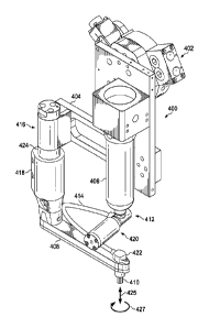
With reference now to Figure 4, an illustration of an isometric view of a
different implementation for a fluid application device is depicted in
accordance with
an illustrative embodiment. In this illustrative example, fluid application
device 400
may be an example of one implementation for fluid application device 100 in
Figure
1.
Fluid application device 400 may include attachment unit 402, platform 404,
cartridge 406, arm 408, brush 410, fluid control system 412, and applicator
movement system 416. Attachment unit 402, platform 404, cartridge 406, arm
408,
brush 410, fluid control system 412, and applicator movement system 416, which
may be examples of implementations for attachment unit 125, platform 114,
cartridge 126, arm 118, brush 148, fluid control system 122, and applicator
movement system 124, respectively, in Figure 1.
In this illustrative example, applicator movement system 416 may be
associated with platform 404. Further, structure 418 may be associated with
applicator movement system 416. Structure 418 may be used to associate arm 408
21
CA 02898323 2015-07-15
with platform 404. Arm 408 may be fixedly associated with platform 404 in this
illustrative example. In other words, neither arm 408 nor structure 418 may be
moved relative to platform 404 in this example.
As depicted, brush 410 may be associated with arm 408. In this illustrative
example, arm 408 may be longer than arm 218 in Figures 2-3. In other words,
arm
408 may be further extended than arm 218. Consequently, arm 408 may be used to
allow brush 410 to be positioned within otherwise difficult to reach
locations.
Fluid control system 412 may include valve system 420, nozzle 422, and
hose 414. Valve system 420 and nozzle 422 may be examples of implementations
for valve system 134 and nozzle 136, respectively, in Figure 1. Valve system
420
and nozzle 422 may be used to control the amount of sealant (not shown) and
the
rate of flow of sealant (not shown), respectively, dispensed through hose 414
from
cartridge 406 to brush 410.
Applicator movement system 416 may include motor 424. Motor 424 may be
operated to rotate brush 410 about applicator axis 425. As one illustrative
example,
operation of motor 424 may cause rotation of brush 410 about applicator axis
425 in
the direction of arrow 427.
With reference now to Figures 5-8, illustrations of a fluid application device
having different configurations for an applicator movement system are depicted
in
accordance with an illustrative embodiment. Fluid application device 500
depicted in
Figures 5-8 may be an example of one implementation for fluid application
device
100 in Figure 1.
Turning now to Figure 5, an illustration of an isometric view of a fluid
application device is depicted in accordance with an illustrative embodiment.
As
depicted, fluid application device 500 may include platform 502, cartridge
504, hose
505, arm 506, brush 508, applicator movement system 510, and attachment unit
512. Platform 502, cartridge 504, hose 505, arm 506, brush 508, applicator
movement system 510, and attachment unit 512 may be examples of
implementations for platform 114, cartridge 126, hose 132, arm 118, brush 148,
and
applicator movement system 124, respectively, in Figure 1. Attachment unit 512
22
CA 02898323 2015-07-15
may be used to attach fluid application device 500 to, for example, without
limitation,
robotic arm 514.
In this illustrative example, cartridge 504 may be configured to dispense
sealant (not shown) to brush 508 through hose 505. Brush 508 may be used to
apply the sealant onto a surface (not shown).
Applicator movement system 510 may be configured to move brush 508. As
depicted, applicator movement system 510 may include first movement system 516
and second movement system 518. First movement system 516 and second
movement system 518 may be an example of one implementation for first movement
system 154 and second movement system 156, respectively, in Figure 1. In this
illustrative example, first movement system 516 and second movement system 518
may be entirely housed within platform 502.
First movement system 516 may be configured to rotate brush 508 about
applicator axis 519. First movement system 516 may include motor 520, shaft
521,
and belt system 523. Belt system 523 may be an example of one implementation
for
belt system 166 in Figure 1. Belt system 523 may include first pulley 522,
second
pulley 524, and belt 526. Second pulley 524 may be associated with applicator
coupling unit 527. Applicator coupling unit 527 may be an example of one
implementation for applicator coupling unit 152 in Figure 1. Applicator
coupling unit
527 may couple brush 508 to arm 506 in this example.
Operation of motor 520 may cause rotation of first pulley 522, which may, in
turn, cause movement of belt 526. Movement of belt 526 may rotate second
pulley
524, which may, in turn cause rotation of brush 508 about applicator axis 519.
As
one illustrative example, brush 508 may be rotated in the direction of arrow
528.
Second movement system 518 may include motor 530, shaft 532, inner gear
534, and outer gear 536. Outer gear 536 may be fixedly attached to arm 506 in
this
example. Operation of motor 530 may rotate shaft 532, which may cause rotation
of
inner gear 534. Rotation of inner gear 534 may cause rotation of outer gear
536,
which may, in turn, cause rotation of arm 506 about arm axis 540. Arm axis 540
may be an example of one implementation for arm axis 174 in Figure 1. For
23
CA 02898323 2015-07-15
example, without limitation, arm 506 may be rotated in the direction of arrow
538
about arm axis 540.
Turning now to Figure 6, an illustration of a cross-sectional view of fluid
application device 500 from Figure 5 is depicted in accordance with an
illustrative
embodiment. In this illustrative example, a cross-sectional view of fluid
application
device 500 from Figure 5 is seen taken along lines 6-6 in Figure 5.
As depicted, fluid application device 500 may have a different configuration
for second movement system 518. In particular, in this example, motor 530 may
be
located outside of platform 502. Additionally, in this view, coupling unit 600
may be
seen. Coupling unit 600 may be configured to couple motor 520 to shaft 521.
With reference now to Figure 7, another illustration of a cross-sectional view
of fluid application device 500 from Figure 6 is depicted in accordance with
an
illustrative embodiment. In this illustrative example, fluid application
device 500 may
have the same configuration for second movement system 518 as depicted in
Figure 5. However, fluid application device 500 may have a different
configuration
for first movement system 516.
In this illustrative example, first movement system 516 may include motor
520, shaft 521, miter gear 702, miter gear 704, shaft 706, miter gear 708,
miter gear
710, shaft 712, and belt system 713. The miter gears may also be referred to
as
bevel gears in some cases. Belt system 713 may include first pulley 714, belt
716,
and second pulley 718.
Operation of motor 520 may cause rotation of shaft 712 and thereby, rotation
of miter gear 702. Rotation of miter gear 702 may, in turn, cause rotation of
miter
gear 704, shaft 706 connected to miter gear 704, and miter gear 708 connected
to
shaft 706. Rotation of miter gear 708 may cause rotation of miter gear 710 and
shaft
712 connected to miter gear 710. Rotation of shaft 712 may cause rotation of
first
pulley 714, which may lead to the rotation of second pulley 718 by belt 716.
Rotation of second pulley 718 may then cause rotation of brush 508 about
applicator
axis 519.
24
CA 02898323 2015-07-15
With reference now to Figure 8, yet another illustration of a cross-sectional
view of fluid application device 500 from Figure 7 is depicted in accordance
with an
illustrative embodiment. In this illustrative example, fluid application
device 500 may
have the same configuration for first movement system 516 as depicted in
Figure 6.
However, fluid application device 500 may have a different configuration for
second
movement system 518.
In this illustrative example, the length of shaft 521 has been extended as
compared to the length of shaft 521 in Figures 5-7. In Figure 8, second
movement
system 518 may include motor 800, turning mechanism 802, shaft 804, belt
system
805, shaft 532, inner gear 534, and outer gear 536. Belt system 805 may
include
first pulley 806, belt 808, and second pulley 810.
Operation of motor 800 may cause activation of turning mechanism 802.
Turning mechanism 802 may be used to activate belt system 805. When belt
system 805 is activated, first pulley 806 may rotate, thereby causing movement
of
belt 808 and rotation of second pulley 810. Rotation of second pulley 810 may
cause rotation of inner gear 534 by shaft 532, which may, in turn cause
rotation of
outer gear 536. Rotation of outer gear 536 may cause rotation of arm 506 about
arm axis 540.
In this illustrative example, turning mechanism 802 may only activate belt
system 805 such that arm 506 may be rotated about arm axis 540 in about 90
degree increments. Turning mechanism 802 may be described in greater detail in
Figure 9.
With reference now to Figure 9, an illustration of a view of turning mechanism
802 from Figure 8 taken with respect to lines 9-9 is depicted in accordance
with an
illustrative embodiment. In this illustrative example, turning mechanism 802
may be
implemented using a Geneva drive mechanism.
As depicted, turning mechanism 802 may include drive wheel 900, driven
wheel 902, and pin 904 attached to drive wheel 900. Driven wheel 902 may have
plurality of slots 905. Plurality of slots 905 includes four slots in this
example. Each
full rotation of pin 904 of about 360 degrees about pivot point 906 may cause
CA 02898323 2015-07-15
rotation of driven wheel 902 by about 90 degrees about pivot point 908. In
this
manner, driven wheel 902 may only be advanced in about 90 degree increments.
Driven wheel 902 may be connected to shaft 804 in Figure 8 at pivot point
908. Shaft 804 in Figure 8 may be connected to first pulley 806 in Figure 8.
Each
advance of driven wheel 902 may cause rotation of shaft 804, and thereby
rotation
of first pulley 806 in Figure 8. Further, first pulley 806 in Figure 8 may
only be
rotated when driven wheel 902 advances. In this manner, the rotation of arm
506 in
Figure 8 may be controlled such that arm 506 remains stabilized when driven
wheel
902 is not being advanced.
With reference now to Figure 10, an illustration of a fluid application device
is
depicted in accordance with an illustrative embodiment. In this illustrative
example,
fluid application device 1000 may be an example of one implementation for
fluid
application device 100 in Figure 1.
Fluid application device 1000 may include platform 1002, cartridge 1004, arm
1006, brush 1008, fluid control system 1010, applicator movement system 1012,
and
attachment unit 1014. Platform 1002, cartridge 1004, arm 1006, brush 1008,
fluid
control system 1010, applicator movement system 1012, and attachment unit 1014
may be examples of implementations for platform 114, cartridge 126, arm 118,
brush
148, fluid control system 122, applicator movement system 124, and attachment
unit
125, respectively, in Figure 1.
In Figure 10, fluid control system 1010 may include valve system 1016, hose
1018, and nozzle 1020. Fluid control system 1010 may be used to control the
dispensing of a sealant held by cartridge 1004 to brush 1008.
In this illustrative example, brush 1008 may be associated with arm 1006
through applicator coupling unit 1022. In this illustrative example, arm 1006
may be
attached to end 1024 of platform 1002.
As depicted, applicator movement system 1012 may include first movement
system 1025. First movement system 1025 may include motor 1026, shaft 1028,
miter gears 1029, telescopic shaft 1030, and miter gears 1032. Operation of
motor
1026 may cause rotation of brush 1008 about applicator 1027 through shaft
1028,
26
miter gears 1029, telescopic shaft 1030, and miter gears 1032. When telescopic
shaft 1030 is present, arm 1006 may be referred to as a telescopic arm.
Applicator movement system 1012 may also include second movement
system 1034. Second movement system 1034 may include motor 1036, belt
system 1037, shaft 1038, belt system 1040, and worm drive mechanism 1042.
Operation of motor 1036 may cause rotation of arm 1006 about arm axis 1035 in
this illustrative example. In particular, operation of motor 1036 may activate
belt
system 1037, which may, in turn, cause activation of belt system 1040 and worm
drive mechanism 1042. Worm drive mechanism 1042 may be configured to
cause rotation of a toothed wheel (not shown) fixedly attached to arm 1006.
In this illustrative example, deployment cylinder 1044 may be used to
extend and retract arm 1006 with respect to arm axis 1035. Arm 1006 may be
connected to deployment cylinder by interface 1046.
With reference now to Figure 11, an illustration of a cross-sectional view
of fluid application device 1000 from Figure 10 is depicted in accordance with
an
illustrative embodiment. In this illustrative example, a cross-sectional view
of
fluid application device 1000 from Figure 10 is depicted taken along lines 11-
11
in Figure 10. A portion of the various components of applicator movement
system 1012 may be more clearly seen in this view.
Turning now to Figure 12, an illustration of a view of fluid application
device 1000 from Figure 10 taken with respect to lines 12-12 is depicted in
accordance with an illustrative embodiment. In this illustrative example, arm
1006 may be configured to extend and retract with respect to arm axis 1035.
For
example, without limitation, arm 1006 may be extended, or lengthened, in the
direction of arrow 1200 along arm axis 1035. This lengthening may be
performed using telescopic element 1201.
Arm 1006 may be configured to move relative to telescopic element 1201
along arm axis 1035. For example, without limitation, arm 1006 may be moved
in the direction of arrow 1200 independently of telescopic element 1201.
Telescopic element 1201 may be associated with telescopic shaft 1030.
27
CA 2898323 2017-06-21
CA 02898323 2015-07-15
Telescopic shaft 1030 may be associated with miter gears 1029 in Figure 10
and miter gears 1032. Rotation of miter gears 1029 caused by motor 1026 in
Figure
may cause rotation of telescopic shaft 1030. The hexagonal shape of telescopic
shaft 1030 may cause telescopic element 1201 to rotate when telescopic shaft
1030
is rotated. Further, interface 1202 between telescopic element 1201 and arm
1006
may ensure that rotation of telescopic element 1201 causes rotation of arm
1006
with telescopic element 1201.
The illustrations of fluid application device 200 in Figures 2-3, fluid
application device 400 in Figure 4, fluid application device 500 in Figures 5-
8,
turning mechanism 802 in Figure 8, fluid application device 1000 in Figures 10-
12
are not meant to imply physical or architectural limitations to the manner in
which an
illustrative embodiment may be implemented. Other components in addition to or
in
place of the ones illustrated may be used.
The different components shown in Figures 2-12 may be illustrative
examples of how components shown in block form in Figure 1 may be implemented
as physical structures. Additionally, some of the components in Figures 2-12
may
be combined with components in Figure 1, used with components in Figure 1, or
a
combination of the two.
With reference now to Figure 13, an illustration of a process for applying a
fluid onto a surface is depicted in the form of a flowchart in accordance with
an
illustrative embodiment. The process illustrated in Figure 13 may be
implemented
using, for example, without limitation, fluid application device 100 to apply
fluid 102
onto surface 104 in Figure 1.
The process may begin by positioning applicator 120 associated with
extension member 117 over surface 104 using robotic operator 108 (operation
1300). Extension member 117 may be configured to maintain a selected distance
between applicator 120 and fluid source 116 for fluid 102. In one illustrative
example, operation 1300 may be performed by robotic operator 108 in the form
of
robotic arm 110.
28
CA 02898323 2015-07-15
Next, fluid 102 may be dispensed from fluid source 116 to applicator 120
associated with extension member 117 (operation 1302). Extension member 117
may hold applicator 120 at some selected distance away from platform 114. In
this
manner, applicator 120 may be positioned within otherwise difficult to reach
areas.
Thereafter, fluid 102 may be applied onto surface 104 using applicator 120
(operation 1304), with the process terminating thereafter. In one illustrative
example, applicator 120 may take the form of brush 148. Brush 148 may be
configured to apply fluid 102 onto surface 104 such that fluid 102 is
substantially
smoothly and evenly distributed.
With reference now to Figure 14, an illustration of a process for applying a
sealant onto a surface is depicted in the form of a flowchart in accordance
with an
illustrative embodiment. The process illustrated in Figure 14 may be
implemented
using, for example, without limitation, fluid application device 100 to apply
sealant
130 onto surface 104 in Figure 1.
Platform 114 of fluid application device 100 may be positioned over surface
104 using robotic arm 110 to which platform 114 is attached (operation 1400).
In
operation 1400, positioning platform 114 may include positioning arm 118
associated with platform 114. Operation 1400 may be performed in a number of
different ways. Robotic arm 110 may be commanded to move platform 114 to move
fluid application device 100 using information provided by a positioning
system. The
positioning system may comprise, for example, without limitation, a vision-
based
positioning system, a preprogrammed coordinate system, or some other type of
positioning system.
The vision-based positioning system may use images generated by cameras
to position fluid application device 100. The pre-programmed coordinate system
may be configured to provide predefined coordinates to robotic arm 110 for
moving
platform 114.
Arm 118 associated with platform 114 may be rotated about arm axis 174
through arm 118 using applicator movement system 124 such that applicator 120
associated with arm 118 is also rotated about arm axis 174 (operation 1402).
29
CA 02898323 2015-07-15
Sealant 130 may be dispensed from fluid source 116 associated with platform
114 to applicator 120 (operation 1404). At least one of amount 142 of and rate
144
of flow of sealant 130 dispensed from fluid source 116 to applicator 120 may
be
controlled using fluid control system 122 (operation 1406).
Applicator 120 may be rotated about applicator axis 158 through applicator
120 independently of arm 118 using applicator movement system 124 (operation
1408). Thereafter, sealant 130 may be applied onto surface 104 using
applicator
120 to seal number of interfaces 131 on surface 104 (operation 1410), with the
process terminating thereafter.
Operation 1408 may be continuously performed during operation 1410 in this
illustrative example. In other words, applicator 120 may be continuously
rotated
while sealant 130 is applied onto surface 104. This type of application of
sealant
130 onto surface 104 may improve the consistency with which sealant 130 is
applied
onto surface 104.
With reference now to Figure 15, an illustration of a process for applying a
sealant onto a plurality of fasteners is depicted in the form of a flowchart
in
accordance with an illustrative embodiment. The process illustrated in Figure
15
may be implemented using fluid application device 100 in Figure 1.
The process may begin moving fluid application device 100 to an initial
position such that brush 148 is positioned over a first fastener in a
plurality of
fasteners installed in a structure using robotic arm 110 (operation 1500).
Brush 148
is then rotated using first movement system 154 of applicator movement system
124
(operation 1502). Valve system 134 is then used to allow a controlled amount
142
of sealant 130 to flow from cartridge 126 to brush 148 at a controlled rate
144
(operation 1504).
Brush 148 is then used to apply sealant 130 to the fastener according to a
predefined application routine (operation 1506). For example, without
limitation,
robotic arm 110 may be used to control the movement of brush 148 over the
fastener by sending commands to second movement system 156 of applicator
movement system 124. The predefined application routine for brush 148 may be a
CA 02898323 2015-07-15
particular pattern according to which brush 148 is to be moved to apply
sealant 130
over the fastener.
Once sealant 130 has been applied to the fastener, the rotation of brush 148
and the flow of sealant 130 to brush 148 are stopped (0perati0n1508). A
determination is then made as to whether any additional fasteners in the
plurality of
fasteners need sealant 130 (operation 1510). If no fasteners in the plurality
of
fasteners still need sealant 130, the process terminates. Otherwise, fluid
application
device 100 is moved to a next position such that brush 148 is positioned over
a next
fastener in the plurality of fasteners using robotic arm 110 (operation 1512).
The
process then returns to operation 1502 as described above.
The flowcharts and block diagrams in the different depicted embodiments
illustrate the architecture, functionality, and operation of some possible
implementations of apparatuses and methods in an illustrative embodiment. In
this
regard, each block in the flowcharts or block diagrams may represent a module,
a
segment, a function, and/or a portion of an operation or step.
In some alternative implementations of an illustrative embodiment, the
function or functions noted in the blocks may occur out of the order noted in
the
figures. For example, in some cases, two blocks shown in succession may be
executed substantially concurrently, or the blocks may sometimes be performed
in
the reverse order, depending upon the functionality involved. Also, other
blocks may
be added in addition to the illustrated blocks in a flowchart or block
diagram.
Illustrative embodiments of the disclosure may be described in the context of
aircraft manufacturing and service method 1600 as shown in Figure 16 and
aircraft
1700 as shown in Figure 17. Turning first to Figure 16, an illustration of an
aircraft
manufacturing and service method is depicted in the form of a flowchart in
accordance with an illustrative embodiment. During pre-production, aircraft
manufacturing and service method 1600 may include specification and design
1602
of aircraft 1700 in Figure 17 and material procurement 1604.
During production, component and subassembly manufacturing 1606 and
system integration 1608 of aircraft 1700 in Figure 17 takes place. Thereafter,
31
CA 02898323 2015-07-15
aircraft 1700 in Figure 17 may go through certification and delivery 1610 in
order to
be placed in service 1612. While in service 1612 by a customer, aircraft 1700
in
Figure 17 is scheduled for routine maintenance and service 1614, which may
include modification, reconfiguration, refurbishment, and other maintenance or
service.
Each of the processes of aircraft manufacturing and service method 1600
may be performed or carried out by a system integrator, a third party, and/or
an
operator. In these examples, the operator may be a customer. For the purposes
of
this description, a system integrator may include, without limitation, any
number of
aircraft manufacturers and major-system subcontractors; a third party may
include,
without limitation, any number of vendors, subcontractors, and suppliers; and
an
operator may be an airline, a leasing company, a military entity, a service
organization, and so on.
With reference now to Figure 17, an illustration of an aircraft is depicted in
the form of a block diagram in which an illustrative embodiment may be
implemented. In this example, aircraft 1700 is produced by aircraft
manufacturing
and service method 1600 in Figure 16 and may include airframe 1702 with
plurality
of systems 1704 and interior 1706. Examples of systems 1704 include one or
more
of propulsion system 1708, electrical system 1710, hydraulic system 1712, and
environmental system 1714. Any number of other systems may be included.
Although an aerospace example is shown, different illustrative embodiments may
be
applied to other industries, such as the automotive industry.
Apparatuses and methods embodied herein may be employed during at least
one of the stages of aircraft manufacturing and service method 1600 in Figure
16.
For example, without limitation, number of interfaces 131 in Figure 1 may be
located
on aircraft 1700. A fluid application device, such as fluid application device
100 from
Figure 1, may be used to apply sealant 130, or some other type of fluid 102,
to
number of interfaces 131 during component and subassembly manufacturing 1606,
system integration 1608, in service 1612, routine maintenance and service
1614,
32
CA 02898323 2015-07-15
and/or some other stage of aircraft manufacturing and service method 1600 in
Figure 16.
In one illustrative example, components or subassemblies produced in
component and subassembly manufacturing 1606 in Figure 16 may be fabricated or
manufactured in a manner similar to components or subassemblies produced
while aircraft 1700 is in service 1612 in Figure 16. As yet another example,
one or
more apparatus embodiments, method embodiments, or a combination thereof may
be utilized during production stages, such as component and subassembly
manufacturing 1606 and system integration 1608 in Figure 16. One or more
apparatus embodiments, method embodiments, or a combination thereof may be
utilized while aircraft 1700 is in service 1612 and/or during maintenance and
service
1614 in Figure 16. The use of a number of the different illustrative
embodiments
may substantially expedite the assembly of and/or reduce the cost of aircraft
1700.
Thus, the illustrative embodiments provide a method and apparatus for
applying fluid onto a surface. In one illustrative embodiment, an apparatus
may
comprise a platform, a fluid source associated with the platform, an arm
associated
with the platform, and an applicator associated with the arm. The fluid source
may
be configured to dispense a fluid. The arm may be configured to extend from
the
platform. The applicator may be configured to receive the fluid dispensed by
the
fluid source. The applicator may be configured for use in applying the fluid
onto a
surface.
In another illustrative embodiment, a fluid application device may comprise a
platform, a cartridge associated with the platform, an arm associated with the
platform, a brush associated with the arm, a fluid control system, an
applicator
movement system, an applicator coupling unit, and an attachment unit. The
cartridge may be configured to dispense a fluid. The arm may be configured to
extend from the platform. The brush may be configured to receive the fluid
dispensed by the cartridge. The brush may be configured for use in applying
the
fluid onto a surface. The fluid control system may be configured to control at
least
33
CA 02898323 2015-07-15
one of an amount of the fluid and a rate of the fluid dispensed to the brush.
The fluid
control system may comprise at least one of a hose, a valve system, and a
nozzle.
The applicator movement system may be configured to move the brush. The
applicator movement system may comprise at least one of a first movement
system
and a second movement system. The first movement system may be configured to
rotate the brush about a brush axis through the brush independently of the
arm. The
first movement system may comprise at least one of a number of motors, a
number
of shafts, a number of belt systems, and a number of gears. The second
movement
system may be configured to rotate the arm about an arm axis through the arm.
Rotation of the arm may cause rotation of the brush about the arm axis. The
second
movement system may comprise at least one of a number of motors, a number of
shafts, a number of belt systems, and a number of gears. The applicator
coupling
unit may be configured to couple the brush to the arm. The attachment unit may
be
configured for association with the platform. The attachment unit may be
configured
for use in attaching the fluid application device to a robotic arm as an end
effector.
The fluid application device described by the various illustrative embodiments
may be used to automate the process of applying fluids, such as sealant, over
surfaces. Further, the fluid application device described by the various
illustrative
embodiments may be used to reduce the time needed to perform these sealant
application operations. Still further, the expense of sealant application
operations
may be reduced by the ability of the fluid application device to control the
amount of
fluid applied and the rate at which the fluid is applied.
The description of the different illustrative embodiments has been presented
for purposes of illustration and description, and is not intended to be
exhaustive or
limited to the embodiments in the form disclosed. Many modifications and
variations
will be apparent to those of ordinary skill in the art. Further, different
illustrative
embodiments may provide different features as compared to other desirable
embodiments. The embodiment or embodiments selected are chosen and
described in order to best explain the principles of the embodiments, the
practical
application, and to enable others of ordinary skill in the art to understand
the
34
CA 02898323 2015-07-15
disclosure for various embodiments with various modifications as are suited to
the
particular use contemplated.