Note: Descriptions are shown in the official language in which they were submitted.
CA 02898592 2015-07-17
1
KNIFE GATE VALVE
DESCRIPTION
OBJECT OF THE INVENTION
The present invention is included in the technical field of knife gate valves.
In particular, the present invention proposes a valve comprising a sleeve
especially designed to allow the correct sealing of the closure without making
a
channel in the valve body for its placement.
BACKGROUND OF THE INVENTION
Knife gate valves are designed for the interruption and/or regulation of the
passage of a fluid. This type of valves comprises a gate therein, this gate
being
the closing element and which allows the closure and opening of an opening
made in the valve body, wherethrough the corresponding fluid passes.
A type of knife gate valves called knife gate valves of unidirectional closure
are known in the state of the art. These comprise a sleeve situated concentric
with
the orifice for the passage of fluid, and the sleeve is positioned in parallel
with said
orifice. Thus, when the gate is in the closed valve position, i.e. plugging
the fluid
through-hole, the sleeve is in frontal contact with the gate. In these valves
the
sleeve is only in contact with one face of the gate.
Another type of valves known in the state of the art are knife gate valves
called bidirectional. These valves comprise a sleeve with a semi-circumference
form which lies in the lower part of the valve, in the area between the end of
the
gate that displaces closing the orifice, and the interior of the valve body
where it
makes contact to close said orifice. The sleeve or seal is peripheral and is
always
in contact with the gate whilst it moves.
A technical problem that the two designs described share is the need to
make an inner channel in the valve opening area. In the first case, a circular
inner
channel is necessary, which has a perimeter slightly greater than that of the
opening and which is situated in parallel to said opening. In the second case,
it is
necessary to make a channel in the lower part of the opening in the interior
whereof the sleeve is trapped when the opening is closed with the gate. To
make
this channel, specific machining means are necessary, in particular cutter bar-
type
machining. The sleeve is placed on this channel when the gate closes, it
presses
CA 02898592 2015-07-17
2
on the sleeve, making it fit into the groove and thus guaranteeing the
sealing.
An important disadvantage of the knife gate valves of the state of the art is
precisely this channel which must be machined in the inner part of the
opening,
since it can be filled with dirt and residues can accumulate in it.
DESCRIPTION OF THE INVENTION
The present invention resolves the mentioned technical problem by a
hybrid knife gate valve which performs a double front closure in the first
part of the
closure path and a peripheral-type closure in the second part of the path,
when
valve closure is completed.
The valve body has an upper part wherein there is a flat notch which
serves as passage for a gate which acts as closing element of the valve. Said
flat
notch extends to a lower part of the valve body wherein there is an opening
for the
passage of fluid.
The double front closure occurs in the upper part of the opening. It is
achieved having the valve gate surrounded by a sleeve, which guarantees the
sealing of the closure, situated on both sides of the gate. Thus, the sleeve
performs pressure from both sides of the gate.
The peripheral closure occurs in the lower part of the opening. It is
achieved having the sleeve comprising a section with a central core which is
the
contact surface of the gate in the closed valve position. In an embodiment of
the
invention this central core may have a contour coinciding with the contour of
the
gate end.
Hence, the valve of the present invention combines the advantages of the
different closure systems of knife gate valves known in the state of the art.
Another important advantage of the design of this valve is that the valve
opening
does not have inner channels for the placement of the sleeve but it is the
actual
sleeve which has a specially designed section to make it possible to obtain
the
two types of aforementioned closures.
The sleeve of the present invention is completely adapted to the valve body
opening. Additionally, the sleeve comprises a groove which coincides with the
flat
notch in the upper part of the opening, allowing the passage of the gate
therethrough. The sleeve section comprises a central core from which recesses
CA 02898592 2015-07-17
3
emerge on both sides.
The valve comprises a pair of fastening rings which are positioned
following the contour of the valve opening. Said additional elements fix the
sleeve
to the valve body and they also act as decorative element as they protrude
from
the lateral faces of the body. In their final position they are separated from
one
another by the gate.
DESCRIPTION OF THE DRAWINGS
To complement the description being made and in order to aid towards a
better understanding of the characteristics of the invention, in accordance
with a
preferred example of practical embodiment thereof, a set of drawings is
attached
as an integral part of said description wherein, with illustrative and non-
limiting
character, the following has been represented:
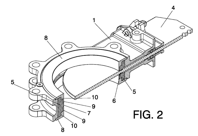
Figure 1. .- Shows an exploded view of the present valve wherein all its
component elements can be observed.
Figure 2. ¨ Shows a sectional view of the knife gate valve of the present
invention.
PREFERRED EMBODIMENT OF THE INVENTION
A detailed description of a preferred embodiment of the invention is de-
scribed below with the aid of figures 1 to 3 mentioned above.
The knife gate valve of the present invention is hybrid and comprises in
the first part of the closure path of the gate, a double front closure, and in
the
second part of the path, when the closure of the opening is completed, a
peripheral-type closure.
In general terms, the knife gate valve of the present invention comprises a
body (1) which has an upper part including a flat notch (2) for the passage of
a
gate (4) which acts as closing element and has a lower part including an
opening
(3). Said flat notch (2) traverses the body (1) from the upper part to the
opening
(3). The most important characteristic of the valve is that it comprises a
sleeve (5)
in the interior of the opening (3) comprising a groove (6) coinciding with the
flat
notch (2) in the upper part of the opening (3) and the section whereof
comprises a
central core (7). In a preferred embodiment said sleeve (5) has recesses on
both
sides of said central core (7). The valve has a pair of fastening rings (8)
which are
CA 02898592 2015-07-17
4
identical and which are placed on both sides of the valve body (1), covering
the
perimeter of the opening (3) and which have an inner section complementary to
the section of the sleeve (5). Figure 1 shows an exploded view of the present
valve wherein all its component elements can be observed.
The flat notch (2) traverses the valve body (1) from the upper part to the
opening (3). The valve further comprises joining means which allow its joining
to
pipes or receptacles between which the valve is positioned in each specific
case.
An important characteristic of the valve of the present invention is that it
does not
include inner channels in the opening (3).
The gate (4) of the present valve is a flat piece which allows opening or
closing the opening (3) to control the passage of a fluid, moving
longitudinally
through the flat notch (2). In a preferred embodiment, the gate (4) has a
semicircular end.
The valve of the present invention fundamentally stands out due to the
sleeve (5), which makes it possible to perform a double front closure and a
peripheral closure in the valve. This sleeve (5) has a circumferential form
and is
placed covering the inner perimeter of the valve opening (3). The outer part
of the
sleeve (5) is a flat surface, coinciding with the flat surface of the interior
of the
opening (3).
The double front closure of the valve is achieved in the upper part of the
opening (3) due to action of the peripheral edge of the groove (6) through the
interior whereof passes the gate (4), so that the gate (4) is interlocked, in
its
displacement, between part of the sleeve (5) on one side of the groove (6),
which presses in one direction, and part of the sleeve (5) on the other side
of
the groove (6), which presses in the other direction. The peripheral-type
closure
is achieved in the lower part of the opening (3) where the total closure of
the
valve occurs when the end of the gate (4) comes into contact with the central
core (7) of the sleeve (5). Figure 2 shows the areas of contact between the
sleeve (5) and the gate (4).
The knife gate valve of the present invention further comprises a pair of
fastening rings (8). These fastening rings (8) are identical to one another
and
are placed one on either side of the valve body (1), covering the perimeter of
CA 02898592 2015-07-17
the opening (3). The function of the fastening rings (8) is to guarantee the
fixing
of the sleeve (5) in its position to the valve body (1). The inner section of
the
fastening rings (8) is complementary to the section of the sleeve (5) and they
have a projecting section which lies over the lateral faces of the valve body
(1).
5 The fastening rings (8) are separated from one another by the gate (4).
In a preferred embodiment of the invention, the sleeve (5) has two
recesses on different sides of the central core (7), as can be observed in
figure
2. Thus, the sleeve (5) comprises a first recess (9) on both sides of the
central
core (7) and comprises a second recess (10) beside the first recess (9). The
inner section of the fastening rings (8) is complementary with the section of
the
sleeve (5) for which reason in this embodiment, the inner section of the
fastening rings comprises a first projection corresponding to the first recess
(9)
and a second projection corresponding to the second recess (10).