Note: Descriptions are shown in the official language in which they were submitted.
TORQUE RIPPLE AND RADIAL FORCE REDUCTION IN DOUBLE-ROTOR
SWITCHED RELUCTANCE MACHINES
[0001] Continue to next paragraph.
FIELD
[0002] Embodiments disclosed herein relate generally to switched
reluctance
machines (SRMs), and more specifically to double-rotor switched reluctance
machines
(DRSRMs).
BACKGROUND
[0003] Hybrid vehicles (e.g. vehicles with more than one power source for
supplying power to move the vehicle) may provide increased efficiency and/or
increased
fuel economy when compared to vehicles powered by a single internal combustion
engine.
[0004] Switched reluctance motor (SRM) drives are gaining interest in
hybrid
(HEV) and Plug-in Hybrid Electric Vehicle (PHEV) applications due to their
simple and
rigid structure, four-quadrant operation, and extended-speed constant-power
range.
However, SRM drives generally suffer from high commutation torque ripple,
typically
resulting from poor tracking precision of phase current, nonlinear inductance
profiles, and
nonlinear torque-current-rotor position characteristics.
[0005] Switched reluctance machines typically include one stator and only
one
rotor. Typically, windings on the stator teeth generate an electromagnetic
field so that the
rotor in the electromagnetic field has the tendency to align with the stator
to achieve
maximum inductance. The rotor can be rotated by successively switching the
stator
excitation.
[0006] A double-rotor electric machine includes at least two rotors and
one stator
integrated into one machine set.
-1-
6868709
Date Recue/Date Received 2021-09-01
CA 02898979 2015-07-30
BRIEF DESCRIPTION OF THE DRAWINGS
[0007] For a better understanding of the described embodiments and to
show
more clearly how they may be carried into effect, reference will now be made,
by way of
example, to the accompanying drawings in which:
[0008] Figure 1A is a schematic axial cross-section view of a double-rotor
switched reluctance machine;
[0009] Figure 1B is a schematic longitudinal cross-section view of
the double-
rotor switched reluctance machine of Figure 1A;
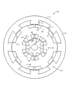
[0010] Figure 2 is a schematic axial cross-section view of another
double-rotor
switched reluctance machine;
[0011] Figure 3A is an example of output torque profiles for an
interior electric
machine, an exterior electric machine, and a resultant total output torque
profile for a
double-rotor electric machine, in which the output torque profiles for the
interior and
exterior electric machines are in-phase;
[0012] Figure 3B is an example of output torque profiles for an interior
electric
machine, an exterior electric machine, and a resultant total output torque
profile for a
double-rotor electric machine in accordance with an example embodiment, in
which the
output torque profiles for the interior and exterior electric machines are
offset;
[0013] Figure 4 is a schematic axial cross-section view of a double-
rotor switched
reluctance machine in accordance with an example embodiment;
[0014] Figure 5 is a schematic axial cross-section view of a double-
rotor switched
reluctance machine in accordance with another example embodiment;
[0015] Figure 6 is a schematic SRM torque control diagram in
accordance with at
least one example embodiment;
[0016] Figure 7A is a schematic axial cross-section view of a double-rotor
switched reluctance machine in which the rotors and the stator are perfectly
concentric;
[0017] Figure 7B is a schematic axial cross-section view of a double-
rotor
switched reluctance machine in which the rotors and the stator are eccentric;
and
- 2 -
CA 02898979 2015-07-30
=
[0018] Figure 7C is a schematic axial cross-section view of the double-
rotor
switched reluctance machine of Figure 7B in which the interior rotor has been
rotated.
[0019] Further aspects and features of the embodiments described
herein will
become apparent from the following detailed description taken together with
the
accompanying drawings. It should be understood, however, that the detailed
description
and the specific examples, while indicating preferred embodiments of the
application,
are given by way of illustration only, since various changes and modifications
within the
spirit and scope of the application will become apparent to those skilled in
the art from
this detailed description.
DESCRIPTION OF EXAMPLE EMBODIMENTS
[0020] Various systems or methods are described below to provide an
example
of an embodiment of each claimed invention. No embodiment described below
limits
any claimed invention and any claimed invention may cover systems and methods
that
differ from those described below. The claimed inventions are not limited to
systems
and methods having all of the features of any one system or method described
below or
to features common to multiple or all of the systems or methods described
below. It is
possible that a system or method described below is not an embodiment of any
claimed
invention. Any invention disclosed in a system or method described below that
is not
claimed in this document may be the subject matter of another protective
instrument, for
example, a continuing patent application, and the applicant(s), inventor(s)
and/or
owner(s) do not intend to abandon, disclaim, or dedicate to the public any
such
invention by its disclosure in this document.
[0021] Switched reluctance motor (SRM) drives are gaining interest in
hybrid
(HEV) and Plug-in Hybrid Electric Vehicle (PHEV) applications due to its
simple and
rigid structure, four-quadrant operation, and extended-speed constant-power
range.
SRM drives have generally been considered to be reliable and cost effective in
harsh
environments due to, for example, the absence of windings and permanent magnet
on
the rotor. But SRM drives generally suffer from high commutation torque
ripple, typically
resulting from poor tracking precision of phase current, nonlinear inductance
profiles,
and nonlinear torque-current-rotor position characteristics.
- 3 -
CA 02898979 2015-07-30
,
[0022] Typical switched reluctance machines include one stator and
only one
rotor. A double-rotor electric machine includes at least two rotors and one
stator
integrated into one machine set. Advantageously, a double-rotor switched
reluctance
machine as described herein may have a high power density, a compact volume
and
size, and/or lower manufacturing costs as compared to two separate electric
machines.
For example, the integration of two rotors and a stator has the advantage of
reducing
the need for another set of stator, machine housing, cooling system, etc., and
thus may
reduce the overall assembly volume at the same power level.
[0023] A double-rotor switched reluctance machine may be operated as
two
individual switched reluctance machines by utilizing the double rotors
separately.
Alternatively, a double-rotor switched reluctance machine may be operated as
one
machine by synchronizing the operation of the two rotors. This may have the
advantage
of enhanced power density as compared with a single-rotor switched reluctance
machine. Alternatively, a double-rotor switched reluctance machine may be
configured
to selectively operate either as two individual switched reluctance machines
or as one
switched reluctance machine (e.g. by selectively synchronizing the rotors).
[0024] A double-rotor switched reluctance machine includes two rotors
rotating
concentrically with the same stator. In the embodiments illustrated herein,
the stator is
nested concentrically between the two rotors so that each of the rotors forms
a
conventional switched reluctance machine with the stator, i.e., the outer
rotor and the
stator form the outer switched reluctance machine while the interior rotor and
the stator
form the inner switched reluctance machine. However, the apparatus and methods
disclosed herein may also be applied to double-rotor switched reluctance
machines
having different configurations.
[0025] For example, in alternative configurations, one of the rotors may be
nested
between the stator and the other rotor so that the middle rotor and stator
form a
conventional switched reluctance machine while the middle rotor and the other
rotor
together form a "floating-stator" switched reluctance machine. A "floating-
stator" means
that the "stator" is actually rotatable and the relative motion between the
two rotors
defines the magnetic field of the second switched reluctance machine. In some
cases,
- 4 -
the machine members are installed concentrically in a radial direction. In
some other
cases, the double rotors and the one stator are installed in a split pattern
so that smaller
radial diameter can be realized. These and various other configurations are
described in
U.S. Patent Publication 2014/0111038 Al.
[0026] Noise and vibration are typical issues for switched reluctance
machines. In
many cases, one or both of these issues result from the relatively high torque
ripple of a
conventional switched reluctance machine. Generally speaking, torque ripple is
the result
of variations in the instantaneous output torque based on, among other things,
the relative
angular position of the rotor poles relative to the stator poles. This results
in periodic
fluctuations in the output torque as the motor shaft rotates. Torque ripple
may be defined
as:
max ¨ Tmin
Trip = (1)
Tõ
[0027] where Tõ, Tmõ, and Tmin, are the average torque, maximum torque,
and
minimum torque, respectively.
[0028] In conventional switched reluctance machines with one stator and
only one
rotor, torque ripple may be reduced in a number of ways, including e.g.
modifying the
physical design of the rotor and/or stator (e.g. shaping the machine pole
teeth topologies),
controlling the phase current profile, and using SRM drives with torque
sharing functions
selected to improve the torque-speed capability of the switched reluctance
machine.
[0029] As disclosed herein, another way to reduce or eliminate torque
ripple from
a machine design perspective can be applied to a double-rotor switched
reluctance
machine topology. In order to reduce the torque ripple, the inner rotor and
the outer rotor
may be synchronized during operation such that the torque waveforms produced
by the
two electric machines have the same electrical frequency and thus a constant
phase
difference exists between the two torque waveforms. By adjusting the relative
positions
of the two torque waveforms, e.g. by adjusting the relative rotor positions, a
-5-
6868718
Date Recue/Date Received 2021-09-01
CA 02898979 2015-07-30
low instantaneous torque output of one machine can be matched to occur
simultaneously with a high instantaneous torque of the other machine, and vice
versa.
Put another way, the relative rotor positions can be adjusted so that the two
torque
output waveforms compensate each other and thus the overall torque ripple for
the
.. double-rotor switched reluctance machine may be reduced.
[0030] In accordance with this broad aspect, there is provided a
double-rotor
switched reluctance machine comprising: a stator, a first rotor, and a second
rotor; the
stator and the first rotor configured to operate as a first electric machine
having an
output torque profile that, for a first average output torque, fluctuates
periodically
between a first maximum instantaneous torque and a first minimum instantaneous
torque as the first rotor rotates relative to the stator; the stator and the
second rotor
configured to operate as a second electric machine having an output torque
profile that,
for a second average output torque, fluctuates periodically between a second
maximum
instantaneous torque and a second minimum instantaneous torque as the second
rotor
rotates relative to the stator; the double-rotor switched reluctance machine
configured
so that when the first and second electric machines are operated at a common
electrical
frequency, the first and second maximum instantaneous torques are temporally
offset,
thereby reducing an overall torque ripple of the double-rotor switched
reluctance
machine.
[0031] In some embodiments, when the first and second electric machines are
operated at the common electrical frequency, the first maximum instantaneous
torque
and the second minimum instantaneous torque are substantially temporally
concurrent.
[0032] In some embodiments, the first rotor is coupled to the second
rotor so that
the first and second electric machines operate at the common electrical
frequency.
[0033] In some embodiments, the first rotor is coupled to the second rotor
so that
the first and second electric machines operate at a common rotational speed.
[0034] In some embodiments, the double-rotor switched reluctance
machine
further comprises a controller for controlling the first and second electric
machines, the
- 6 -
CA 02898979 2015-07-30
=
controller operable to selectively synchronize the first and second electric
machines to
operate at the common electrical frequency.
[0035] In some embodiments, the controller comprises a first
controller for
controlling the first electric machine, and a second controller for
controlling the second
electric machine.
[0036] In some embodiments, the second rotor is nested within the
first rotor.
[0037] In some embodiments, the first rotor is nested within the
stator.
[0038] In some embodiments, the stator is nested between the first
rotor and the
second rotor.
[0039] In some embodiments, the double-rotor switched reluctance machine is
further configured so that when the first and second electric machines are
operated at a
common rotational speed, the first and second rotors are radially offset from
each other
by a predetermined offset angle selected to reduce a net radial force imposed
on the
stator by the operation of the first and second electric machines.
[0040] In some embodiments, the predetermined offset angle is selected to
minimize the net radial force imposed on the stator by the operation of the
first and
second electric machines.
[0041] Also in accordance with this broad aspect, there is provided a
method for
controlling a double rotor switched reluctance machine comprising a stator, a
first rotor,
and a second rotor, the stator and the first rotor configured to operate as a
first electric
machine, and the stator and the second rotor configured to operate as a second
electric
machine, the method comprising: operating the first electric machine at an
electrical
frequency to generate a first average output torque, the first electric
machine having an
output torque profile that fluctuates periodically between a first maximum
instantaneous
torque and a first minimum instantaneous torque as the first rotor rotates
relative to the
stator; operating the second electric machine at the electrical frequency to
generate a
second average output torque, the second electric machine having an output
torque
profile that fluctuates periodically between a second maximum instantaneous
torque
- 7 -
CA 02898979 2015-07-30
,
and a second minimum instantaneous torque as the second rotor rotates relative
to the
stator; and synchronizing the operation of the first and second electric
machines so that
the first and second maximum instantaneous torques are temporally offset,
thereby
reducing an overall torque ripple of the double-rotor switched reluctance
machine.
[0042] In some embodiments, synchronizing the operation of the first and
second
electric machines comprises operating the first and second electric machines
so that the
first maximum instantaneous torque and the second minimum instantaneous torque
are
substantially temporally concurrent.
[0043] In some embodiments, synchronizing the operation of the first
and second
electric machines comprises coupling the first rotor to the second rotor so
that the first
and second electric machines operate at the same electrical frequency.
[0044] In some embodiments, synchronizing the operation of the first
and second
electric machines comprises using a controller operable to selectively
synchronize the
first and second electric machines to operate at the same electrical
frequency.
[0045] In some embodiments, the method further comprises synchronizing the
operation of the first and second electric machines so that the first and
second rotors
are radially offset from each other by a predetermined offset angle selected
to reduce a
net radial force imposed on the stator by the operation of the first and
second electric
machines.
[0046] Another typical cause of noise and vibration in conventional
switched
reluctance machines is a relatively high radial force. Generally speaking,
this radial
force is typically a result of an eccentricity (e.g. non-concentricity) of the
machine rotor
stator assembly, although it may also be the result of variations and/or
asymmetries in
the stator and/or rotor. For example, if the air gap between the stator and
rotor is not
perfectly uniform, the location with the smaller air gap distance will yield a
higher radial
force pulling the rotor towards the stator, resulting in a net radial force on
the machine.
As the rotor rotates relative to the stator, the location of the higher radial
force will also
rotate. This results in a rotating net force on the machine as the motor shaft
rotates.
- 8 -
CA 02898979 2015-07-30
[0047] As disclosed herein, the net radial force may be reduced or
eliminated
from a double-rotor switched reluctance machine topology. In order to reduce
the radial
force, the inner rotor and the outer rotor may be synchronized during
operation such
that the radial forces from each machine at least partially cancel each other
out, and
.. thus the overall radial force for the double-rotor switched reluctance
machine may be
reduced.
[0048] In accordance with this broad aspect, there is provided a
double-rotor
switched reluctance machine comprising: a stator, a first rotor, and a second
rotor, the
stator and the first rotor configured to operate as a first electric machine,
and the stator
and the second rotor configured to operate as a second electric machine; the
double-
rotor switched reluctance machine configured so that when the first and second
electric
machines are operated at a common rotational speed, the first and second
rotors are
radially offset from each other by a predetermined offset angle selected to
reduce a net
radial force imposed on the stator by the operation of the first and second
electric
machines.
[0049] In some embodiments, the predetermined offset angle is selected
to
minimize the net radial force imposed on the stator by the operation of the
first and
second electric machines.
[0050] Also in accordance with this broad aspect, there is provided a
method for
controlling a double rotor switched reluctance machine comprising a stator, a
first rotor,
and a second rotor, the stator and the first rotor configured to operate as a
first electric
machine, and the stator and the second rotor configured to operate as a second
electric
machine, the method comprising: operating the first electric machine and the
second
electric machine at a common rotational speed; and synchronizing the operation
of the
first and second electric machines so that the first and second rotors are
radially offset
from each other by a predetermined offset angle selected to reduce a net
radial force
imposed on the stator by the operation of the first and second electric
machines.
- 9 -
CA 02898979 2015-07-30
=
[0051] In some embodiments, the predetermined offset angle is selected
to
minimize the net radial force imposed on the stator by the operation of the
first and
second electric machines.
[0052] These and other aspects and features of various embodiments
will be
described in greater detail below. While some examples discussed herein are
directed
to double-rotor SRMs for hybrid vehicle applications, it will be appreciated
that the
torque-ripple and/or radial force reduction techniques disclosed herein may be
applied
to any type of double-rotor SRM drive and/or any type of double-rotor electric
machine.
[0053] Furthermore, it will be appreciated by a person skilled in the
art that a
method or apparatus disclosed herein may embody any one or more of the
features
contained herein and that the features may be used in any particular
combination or
sub-combination.
[0054] Reference is now made to Figure 1A, which illustrates a
schematic axial
cross-section of an example double-rotor switched reluctance machine 100.
Double-
.. rotor switched reluctance machine 100 includes an exterior rotor 111, an
interior rotor
121, and a stator 112 nested concentrically between the exterior rotor 111 and
the
interior rotor 121. Exterior and interior rotors 111, 121 each rotate
coaxially about output
shaft 129, while stator 112 typically does not rotate relative to the machine
housing.
[0055] In the illustrated example, stator 112 is shared by both the
exterior rotor
.. 111 and the interior rotor 121. Specifically, stator 112 and exterior rotor
111 form an
exterior switched reluctance machine, referred to generally as 110, and stator
112 and
interior rotor 121 form an interior switched reluctance machine, referred to
generally as
120.
[0056] The exterior side of the stator 112 is salient with exterior
stator poles 116
and the interior side of the stator 112 is salient with interior stator poles
126. This may
allow the switched reluctance machine 100 to achieve a higher aligned
inductance to
unaligned inductance ratio so that a higher torque density and a higher power
density
can be realized.
- 10-
CA 02898979 2015-07-30
[0057] Exterior switched reluctance machine 110 includes exterior
rotor 111, an
exterior side of the stator 112, and exterior stator coils 113. The exterior
rotor 111 is
also salient with rotor poles 115. An air gap 114 is formed between the rotor
poles 115
and the exterior stator poles 116.
[0058] In the illustrated example, exterior stator poles 116 have coil
windings 113
to selectively generate magnetic fields. In this example, there are no coil
windings on
the rotor poles 115. The exterior coil windings 113 generate magnetic flux
through the
exterior stator poles 116. The flux penetrates the air gap 114 between the
exterior stator
poles 116 and the rotor poles 115 and then goes into the exterior rotor 111.
The flux
between the exciting or energized exterior stator poles 116 and the
corresponding rotor
poles 115 tends to align the rotor poles 115 with the exciting exterior stator
poles 116 so
that the rotor rotates.
[0059] Exterior rotor 111 can be continuously rotated by successively
switching
the stator excitation. For example, exciting stator coil windings 113 to
change phase
from one pole to another in sequence according to the angular position of
rotor 111
urges the exterior machine to keep rotating. The flux then splits by half into
the back
iron 117 of the exterior rotor 111 and merges again at the other end of the
rotor pole
115. The flux then again goes through the rotor pole 115, the air gap 114, and
the
exterior stator pole 116 on the other side of the exterior rotor 111.
Eventually, the flux
splits again in the exterior stator back iron 118 and merges at the base of
the exterior
stator pole 116 where the flux is generated.
[0060] Interior switched reluctance machine 120 includes an interior
rotor 121, an
interior side of the stator 112, and interior stator poles 126. The interior
rotor 121 is also
salient with rotor poles 125. An air gap 124 is formed between the rotor poles
125 and
the interior stator poles 126.
[0061] In the illustrated example, the interior stator poles 126 have
interior coil
windings 123 to selectively generate magnetic fields. In this example, there
are no coil
windings around the interior rotor poles 125. The interior coil windings 123
generate
magnetic flux through the interior stator poles 126. The flux penetrates the
air gap 124
-11-
CA 02898979 2015-07-30
between the interior stator poles 126 and the interior rotor poles 125 and
then goes into
the interior rotor 121. The flux between the exciting stator poles 126 and the
corresponding rotor poles 125 tends to align the interior rotor poles 125 with
the exciting
interior stator poles 126 so that the rotor rotates.
[0062] Interior rotor 121 can be continuously rotated by successively
switching
the stator excitation. For example, exciting stator coil windings 123 to
change phase
from one pole to another in sequence according to the angular position or
rotor 121
urges the interior machine to keep rotating. The flux then splits by half into
the back iron
127 of the interior rotor 121 around the interior shaft 129 and merges again
at the other
end of the interior rotor pole 125 of the interior rotor 121. The flux then
again goes
through the interior rotor pole 125, the interior air gap 124, and the
interior stator pole
126 on the other side of the interior rotor 121. Eventually, the flux splits
in the interior
stator back iron 128 and merges at the base of the interior stator pole 126
where the
flux is generated.
[0063] The flux paths described above for the exterior switched reluctance
machine 110 and the interior switched reluctance machine 120, and in the
application
overall, are for illustration purposes only. In fact, there may be neither a
starting point
nor an ending point of the flux path. The whole flux path may be an entire
loop formed
by the entire exterior switched reluctance machine 110 and the entire interior
switched
reluctance machine 120. By having the coil windings 113 and 123 only around
the
exterior stator poles 116 and interior stator poles 126, respectively, the
switched
reluctance machine 100 may advantageously have a relatively simple
construction.
[0064] In some embodiments, each electric machine 110, 120 may be
independently selectively operable as either an electric motor or as an
electric
generator. When operating as an electric motor, the electric machine is
capable of
converting electrical energy (from e.g. a battery, a capacitor, or other power
source) into
mechanical energy to produce an output power (or torque). When operating as an
electric generator, the electric machine is capable of converting mechanical
energy
(from e.g. a shaft or other mechanical input) into electrical energy, which
may be
transferred to e.g. a battery, a capacitor, or other power source.
- 12-
CA 02898979 2015-07-30
=
[0065] Exterior rotor 111 and interior rotor 121 are concentrically
aligned so that
they share the same rotating axis. Stator 112 is designed so that the flux
paths
described above are independently functioning without major flux coupling and
the
exterior switched reluctance machine 110 and the interior switched reluctance
machine
120 work independently. Optionally, an insulation layer may be provided in the
stator
112 between the exterior switched reluctance machine 110 and the interior
switched
reluctance machine 120 to separate the flux paths of the two switched
reluctance
machines.
[0066] Reference is next made to FIG. 1B, which illustrates a
schematic
longitudinal cross-section of double-rotor switched reluctance machine 100.
Double-
rotor switched reluctance machine 100 provides two mechanical output paths:
one from
the exterior rotor 111, and the other from the interior rotor 121. The
exterior rotor 111 is
coupled to an exterior shaft 119, and the interior rotor 121 is coupled to an
interior shaft
129. In the illustrated example, rotor 111 and shaft 119 are integrally
formed, as are
rotor 121 and shaft 129. It will be appreciated that the rotors may
alternatively be
coupled using any suitable method, such as a threaded coupling, a keyed joint,
welding,
adhesives, and the like.
[0067] In the illustrated configuration, both the exterior and
interior rotors 111,
121 (and accordingly the two output shafts 119, 129) can be controlled
independently
by the exterior switched reluctance machine 110 and the interior switched
reluctance
machine 120, respectively.
[0068] As illustrated in FIG. 1B, exterior output shaft 119 is
positioned at one end
of the double-rotor switched reluctance machine, while the interior output
shaft 129 has
terminal ends at both ends of machine 100. In alternative embodiments, output
shafts
119 and 129 may have a different number of terminal ends, e.g. terminal ends
for one
or both output shafts may be provided at one or both ends of machine 100.
[0069] In the example illustrated in FIG. 1A, double-rotor switched
reluctance
machine 100 has six exterior stator poles 116 and eight exterior rotor poles
115.
Accordingly, exterior switched reluctance machine 110 may be characterized as
a 6/8
-13-
CA 02898979 2015-07-30
=
switched reluctance machine. Double-rotor switched reluctance machine 100 also
has
six interior stator poles 126 and eight interior rotor poles 125. Accordingly,
interior
switched reluctance machine 120 may also be characterized as a 6/8 switched
reluctance machine. However, it will be appreciated that the number of rotor
and stator
poles are for illustration only, and that alternative embodiments of double-
rotor switched
reluctance machine 100, the interior and exterior electric machines may have
any
number of stator poles, rotor poles, and coil windings.
[0070] For example, in some embodiments other pole pair patterns,
such as
stator pole to rotor pole ratios, of 6/4, 8/6, 6/8, 6/10, 12/8, 8/14, etc.,
may be used. Also,
the number of stator and rotor poles for the interior and exterior electric
machines may
be the same or may be different. FIG. 2 illustrates a schematic axial cross-
section
example of another double-rotor switched reluctance machine 100, in which
exterior
switched reluctance machine 110 has six exterior stator poles 116 and eight
exterior
rotor poles 115 (and may therefore be characterized as a 6/8 SRM), and
interior
switched reluctance machine 120 has six interior stator poles 126 and four
interior rotor
poles 125 (and may therefore be characterized as a 6/4 SRM).
[0071] In order to reduce or eliminate the torque ripple of a double-
rotor switched
reluctance machine 100, the inner rotor and the outer rotor may be
synchronized during
operation such that the output torque profile (i.e. instantaneous torque as a
function of
the rotational angle of the rotor) for each of the two electric machines 110,
120 have the
same electrical frequency, and thus a constant phase difference exists between
the
respective minimum and maximum instantaneous torque for the first and second
electrical machines.
[0072] Fig. 3A is an example of an output torque profile 220 for an
interior electric
machine 120, an output torque profile 210 for an exterior electric machine
110, and the
resultant total output torque profile 240a for the double-rotor electric
machine 100. As is
typical for switched reluctance machines, each output torque profile 210, 220
fluctuates
periodically between a maximum instantaneous torque and a minimum
instantaneous
torque as the rotor for that machine rotates relative to the stator.
-14-
CA 02898979 2015-07-30
=
[0073] In Figure 3A, the output torque profiles 210, 220 may be
characterized as
in-phase, as the maximum instantaneous torque for electric machine 110 occurs
substantially simultaneously (i.e. is substantially temporally aligned) with
the maximum
instantaneous torque for electric machine 120, and the minimum instantaneous
torque
.. for electric machine 110 occurs substantially simultaneously (i.e. is
substantially
temporally aligned) with the minimum instantaneous torque for electric machine
120.
[0074] By adjusting the relative positions of the two output torque
profiles, a
relatively low instantaneous torque output of one electric machine can be
matched to
occur simultaneously with a relatively high instantaneous torque of the other
electric
machine, and vice versa. Put another way, double-rotor electric machine 100
can be
configured so that the two torque output waveforms of electric machines 110,
120 at
least partially compensate or offset each other and thus the overall torque
ripple for the
double-rotor switched reluctance machine 100 may be reduced.
[0075] For example, the output torque profiles 210, 220 shown in
Figure 3B may
be characterized as out-of-phase, as the maximum instantaneous torque for
electric
machine 110 occurs substantially simultaneously (i.e. is substantially
temporally
aligned) with the minimum instantaneous torque for electric machine 120, and
the
minimum instantaneous torque for electric machine 110 occurs substantially
simultaneously (i.e. is substantially temporally aligned) with the maximum
instantaneous
.. torque for electric machine 120. Put another way, the maximum instantaneous
torques
for electric machines 110, 120 are temporally offset, which results in a
'flatter overall
output torque profile 240b (i.e. less overall torque ripple) for the double-
rotor switched
reluctance machine 100.
[0076] One way in which the output torque profiles of the electric
machines 110,
120 can be adjusted to at least partially compensate or offset each other is
by adjusting
the relative angular position of rotors 111, 121 during operation of the first
and second
electric machines 110, 120. For example, in FIG. 1A both the exterior and
interior
switched reluctance machines 110, 120 are 6/8 switched reluctance machines.
Also,
rotor poles 115 are generally radially aligned with rotor poles 125. Operating
electric
machines 110, 120 at the same electrical frequency and with the rotors 111,
121 in the
-15-
CA 02898979 2015-07-30
=
relative position shown in Figure 1A may result in output torque profiles for
electric
machines 110, 120, and an overall torque profile for the double-rotor switched
reluctance machine 100 as shown in Fig. 3A. However, as shown in Fig. 4, rotor
poles
115 may be generally radially aligned with the gaps between rotor poles 125.
In other
.. words, the rotor poles 115, 125 are radially offset (i.e. not radially
aligned). Operating
electric machines 110, 120 at the same electrical frequency and with the
rotors 111, 121
in the relative position shown in Figure 4 may result in output torque
profiles for electric
machines 110, 120, and an overall torque profile for the double-rotor switched
reluctance machine 100 as shown in Fig. 3B.
[0077] In Figures 1A and 4, stator poles 116 are generally radially aligned
with
stator poles 126. Alternatively, as shown in Fig. 5, the stator poles 116, 126
may be
radially offset (i.e. not radially aligned). Operating electric machines 110,
120 at the
same electrical frequency and with the rotors 111, 121 in the relative
position shown in
Figure 5 (i.e. aligned) but with offset stator poles 116, 126 may result in
output torque
profiles for electric machines 110, 120, and an overall torque profile for the
double-rotor
switched reluctance machine 100 as shown in Fig. 3B.
[0078] For the double-rotor switched reluctance machine
configurations shown in
Figures 1A and 4, the exterior and interior electric machines have the same
number of
rotor and stator poles (i.e. electric machines 110 and 120 are both 6/8 SRMs).
Accordingly, for electric machines 110 and 120 to operate at a common
electrical
frequency, rotors 111 and 121 have to run at the same rotational speed (e.g.
at the
same revolutions per minute, or RPM). However, in embodiments where the
interior
electric machine does not have the same rotor/stator pole configuration as the
exterior
electric machine, operating the electric machines 110, 120 at a common
electrical
frequency may require the rotors 111, 121 to operate at different RPMs. For
example,
for the double-rotor switched reluctance machine illustrated in Figure 2,
since the
exterior rotor 111 has twice the number of rotor poles of the interior rotor
121, and there
are the same number of stator poles 116, 126 (i.e. interior electric machine
is a 6/4
SRM, and exterior electric machine is a 6/8 SRM), the interior rotor 121 has
to run at
-16-
CA 02898979 2015-07-30
twice the RPMs as exterior rotor 111 for interior electric machine 120 to
operate at the
same electrical frequency as exterior electric machine 110.
[0079] Generally speaking, for double-rotor switched reluctance
machine
configurations where operating the electric machines 110, 120 at a common
electrical
frequency requires the rotors to operate at a common RPM, the relative angular
positions of the rotors may be expressed as:
02 = 61 + offset (2)
where 01 is the angular position of the rotor of the first electric machine,
02 is the
angular position of the rotor of the second electric machine, and 00f fset is
a
predetermined angular offset (based on e.g. the double-rotor switched
reluctance
machine configuration) to be maintained between the rotors.
[0080] For double-rotor switched reluctance machine configurations
where
operating the electric machines 110, 120 at a common electrical frequency
requires the
rotors to operate at different RPMs, the relative angular positions of the
rotors may be
expressed as:
02 = C(01) + of fset (3)
where c is a constant based on the speed ratio to be maintained between the
rotors. For
example, if the first rotor has to rotate twice as fast as the second rotor
for the electric
machines to operate at the same electrical frequency, c is equal to 1/2.
[0081] One way to maintain a desired offset between the output torque
profiles
for the exterior and interior electric machines is to mechanically synchronize
rotors 111
and 121 to maintain a desired relative alignment of the rotors. For example,
the two
rotors may be coupled to each other and/or to a common output shaft with the
rotors
radially offset from each other by a predetermined offset angle selected to
provide a
desired overall torque ripple for the double-rotor switched reluctance machine
100.
[0082] In double-rotor switched reluctance machine configurations
where rotors
111 and 121 have to run at a common rotational speed for electric machines 110
and
-17-
CA 02898979 2015-07-30
=
120 to operate at a common electrical frequency, the two rotors may be coupled
directly
to each other and/or directly to a common output shaft.
[0083] In double-rotor switched reluctance machine configurations
where rotors
111 and 121 have to run at different rotational speeds for electric machines
110 and
120 to operate at a common electrical frequency, the two rotors may be coupled
to each
other and/or to a common output shaft so that a predetermined ratio between
the
rotational speeds of the rotors is maintained. For example, for the double-
rotor switched
reluctance machine illustrated in Figure 2, the rotors may be mechanically
synchronized
so that the interior rotor completes two revolutions for every one revolution
of the
exterior rotor. It will be appreciated that the rotors may be coupled to each
other in any
suitable fashion, e.g. via one or more reduction gears, and/or at least one of
the two
rotors may be coupled to a common output shaft via one or more reduction
gears.
[0084] Another way to maintain a desired offset between the output
torque
profiles for the exterior and interior electric machines is to electrically
control machines
110 and 120 to maintain a desired relative alignment of rotors 111 and 121.
For
example, the two electric machines may be operated using the same current
excitation
frequency, or a predetermined ratio between the current excitation frequencies
may be
maintained so that a predetermined ratio between the rotational speeds of the
rotors is
maintained.
[0085] An example schematic SRM torque control diagram 600 is shown in
Figure 6. This example is provided for illustration only, and other control
systems and/or
methods may be used to control e.g. switched reluctance machines 110, 120. In
the
illustrated example, an input (or desired) torque reference 605 is distributed
to three
phases based on values determined using a torque sharing function (TSF) 610
for a
given rotor position O. These individual phase torque references 615a, 615b,
and 615c
(as defined by the TSF) are then converted to phase current references 625a,
625b,
625c according to torque-current-rotor position characteristics 620 of the SRM
motor
650. Finally, the phase current is controlled by a hysteresis controller 630.
A power
converter 660 may be provided.
-18-
CA 02898979 2015-07-30
=
[0086] It will be appreciated that the individual phase torque
references 615a,
615b, and 615c for a given torque reference 605 and rotor position 6 may be
pre-
determined and stored in one or more look-up tables, for example using a field-
programmable gate array (FPGA), a digital signal processor (DSP), and/or other
suitable controller.
[0087] Similarly, the phase current reference (e.g. 625a, 625b, 625c)
for a given
phase torque reference (e.g. 615a, 615b, and 615c) and rotor position 0 may be
pre-
determined and stored in one or more look-up tables, for example using a FPGA
or
other suitable controller.
[0088] Also, in some embodiments, the torque-current-rotor position
characteristics 620 may be taken into consideration when determining
individual phase
current references 625a, 625b, and 625c based on the TSF. For example, three
look-up
tables ¨ from which an individual phase current reference (e.g. 625a, 625b,
625c) can
be retrieved for an individual phase torque reference (e.g. 615a, 615b, and
615c) and
rotor position 0 ¨ may be used.
[0089] In the example control system illustrated in Figure 6, the
phase current
reference is a function of a desired output torque and rotor position O.
Accordingly, for a
double-rotor switched reluctance machine employing such a control system for
one or
both electric machines 110, 120, the relative positions of rotor 111 and 121
could be
compared (e.g. by a central controller, or by a controller for machine 110 or
120) and if
the relative angular positions of the rotors is determined to vary from a
predetermined
offset angle, the rotational speed of one or both rotors may be temporally
adjusted
(increased or decreased) to return the rotors to the predetermined offset
angle.
[0090] In addition to torque ripple, during the operation of switched
reluctance
machines an unbalanced radial force is typically present. This radial force is
typically the
result of an eccentricity of the machine rotor stator assembly (e.g. due to
manufacturing
tolerances), which leads to a non-uniform air gap between the rotor and the
stator. A
location with a smaller air gap distance yields a higher radial force pulling
the rotor
towards the stator than a location with a higher air gap distance, and vice
versa. It will
- 19-
CA 02898979 2015-07-30
=
be appreciated that the location of the higher radial force rotates as the
rotor rotates
relative to the stator, resulting in a moving force that may generate
vibration and/or
noise, or otherwise impair the performance of the switched reluctance machine.
[0091] As shown schematically in FIGs. 7A-C, in a double-rotor
switched
reluctance machine 100, there are two air gaps 114 and 124. Since the stator
112 is
nested between the two rotors 111 and 121, the net radial force acting on the
stator 112
is a combination of the radial force from the exterior machine 110 and the
interior
machine 120. Accordingly, when the rotors are rotating at a common rotational
speed
(i.e. are in a fixed relative position), the net radial force can be reduced
(e.g. partially or
.. completely balanced) by selecting the relative position of the two rotors
111 and 121 to
reduce or minimize the net variance in the air gaps 114, 124.
[0092] In FIG. 7A, the rotors are perfectly concentric with each other
and with the
stator. Accordingly, the air gaps in the inner and outer electric machines are
constant,
and there is no net radial force. While such a configuration is theoretically
possible, it
may not always be achieved.
[0093] For example, in FIG. 7B, the interior machine 120 has a smaller
air gap on
the left side, which results in rotor 121 pulling the stator 112 towards the
right side. The
exterior machine 110 has a smaller air gap on the right side, which results in
rotor 111
pulling the stator 112 towards the right side as well, thus adding to the net
radial force
exerted on the stator of the double-rotor electric machine 100.
[0094] In Figure 7C, the interior rotor 121 has been rotated while the
exterior
rotor 111 has not, so that the interior machine 120 has a smaller air gap on
the right
side, which results in rotor 121 pulling the stator 112 towards the left side.
The exterior
machine 110 still has a smaller air gap on the right side, which results in
rotor 111
pulling the stator 112 towards the right side. Thus the net radial force on
the stator 112
is reduced or balanced between the interior machine 120 and the exterior
machine 110.
This may reduce or eliminate wobble, noise and/or vibration of the double-
rotor electric
machine 100.
- 20 -
CA 02898979 2015-07-30
[0095] To selecting a relative position of the two rotors and to
reduce or minimize
the net variance in the air gaps, the eccentricity of each electric machine
may be
determined independently (e.g. by operating one electric machine while the
other
electric machine is stopped), and a preferred relative position may be
determined to
.. reduce or minimize the net forces expected based on the determined
eccentricities.
Alternatively, both electric machines may be operated concurrently, and during
operation the relative position of the rotors may be varied (e.g. by
electrically over- or
under-speeding one rotor) while the net radial force is measured (e.g. using
an
accelerometer mounted to the stator) to determine the relative rotor position
that leads
.. to a reduced (e.g. minimized) net radial force. It will be appreciated that
instead of (or in
addition to) measuring the net radial force on the stator, the overall wobble
and/or
vibration of the double-rotor switched reluctance machine may be measured to
infer the
net radial force.
[0096] In double-rotor switched reluctance machine configurations
where rotors
111 and 121 have to run at a common rotational speed for electric machines 110
and
120 to operate at a common electrical frequency, the rotors may be configured
to
reduce both torque ripple and radial force imbalances. In this respect,
depending on the
stator/rotor pole configurations of the first and second electric machines,
there will often
be a plurality of relative rotor positions that may be used to reduce the
overall torque
ripple of the double-rotor switched reluctance machine. For example, for an
eight-pole
SRM driven by a three-phase power supply (which may be characterized as a 24
stroke
SRM), the peak instantaneous torque is expected to occur 24 times (e.g. at 24
different
mechanical angles) per revolution of the rotor relative to the stator. Thus,
there may be
24 different possible mechanical angles between the stator and the rotor that
at which
the peak instantaneous torque is produced. Accordingly, each of these
mechanical
angles may be used to temporally offset the peak instantaneous torque for that
electric
machine relative to a peak instantaneous torque generated by the other
electric
machine in a double-rotor electric machine. However, as shown in Figure 70,
there may
only be one mechanical angle between the rotors that results in a minimal net
radial
force. Accordingly, one may select the one of the plurality of mechanical
angles suitable
- 21 -
CA 02898979 2015-07-30
=
to offset the peak instantaneous torque that is closest to the mechanical
angle that
results in a minimal net radial force, in order to reduce both torque ripple
and net radial
force.
[0097] It will be appreciated that in some embodiments, one may
select a
mechanical angle that is between an angle that would be optimal to reduce
torque ripple
and an angle that would be optimal to minimize net radial force, to provide a
tradeoff
between torque ripple reduction and net radial force reduction.
[0098] The various embodiments described herein may have applications
in the
fields of hybrid electric vehicle powertrain, hybrid electric aircraft
powertrain, hybrid ship
powertrain, or some other electro-mechanical integrated transmission to serve
as the
electric prime mover and receiver. The various embodiments described herein
may
further have applications in hybrid electric and plug-in hybrid electric
vehicles, such as,
for example, cars, SUVs, trucks, motorbikes, etc., to replace the existing or
conventional
motor and generators in transmissions power train.
[0099] As used herein, the wording "and/or" is intended to represent an
inclusive-
or. That is, "X and/or Y" is intended to mean X or Y or both, for example. As
a further
example, "X, Y, and/or Z" is intended to mean X or Y or Z or any combination
thereof.
[00100] While the above description describes features of example
embodiments,
it will be appreciated that some features and/or functions of the described
embodiments
are susceptible to modification without departing from the spirit and
principles of
operation of the described embodiments. For example, the various
characteristics which
are described by means of the represented embodiments or examples may be
selectively combined with each other. Accordingly, what has been described
above is
intended to be illustrative of the claimed concept and non-limiting. It will
be understood
by persons skilled in the art that variations are possible in variant
implementations and
embodiments.
- 22 -